
Subscribe to Our Youtube Channel
Related Manuals for Emerson RLDS


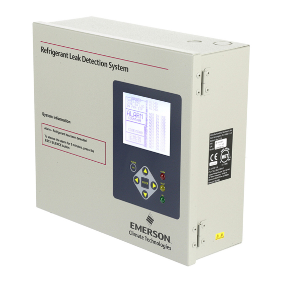
Summary of Contents for Emerson RLDS
- Page 1 Refrigerant Leak Detection System (RLDS) Installation and Operation Manual 026-1309 Rev 8...
- Page 3 770-425-2724 • www.emerson.com CE/FCC Compliance Notice Information Class A compliance for RLDS under CE Requirements. Meets Part 15 Subpart B requirements of the FCC Rules. In a domestic environment this product may cause radio interference in which case the user may be required to take adequate measures.
-
Page 5: Table Of Contents
1.3.4. Proper Exhaust Venting ............................1 1.3.5. Working Inside Instrument............................ 1 1.3.6. Misuse and Modifications to the Instrument......................1 1.3.7. In Case of Malfunction............................1 1.3.8. RLDS Fusing ................................. 2 1.3.9. Installation Category ............................2 1.3.10. Altitude Limit............................... 2 1.3.11. Cleaning ................................2 1.4. - Page 6 5 RLDS - CONNECTING EXTERNAL ALARMS..................... 22 5.1. O .................................. 22 VERVIEW 5.2. C ................................22 ONNECTION 6 RLDS HARDWARE SPECIFICATIONS ......................... 23 7 PROGRAMMING SETUP AND UI NAVIGATION FOR RLDS - DISPLAY SCREENS........25 7.1. N ..............................25 AVIGATION 7.2. I ..............................25 NITIAL OWER 7.3.
- Page 7 8.7.2. Navigating to the Fault Screen ........................... 34 8.7.2.1. Critical Faults..................................34 8.7.2.2. Non-Critical Faults ................................34 8.7.3. Reset to Factory Default Settings........................35 8.7.3.1. Resetting the RLDS ................................35 8.7.4. Clearing System Faults ............................35 8.7.5. Viewing Fault Log............................... 35 8.7.6. Viewing Flow Log ............................... 36 8.8.
- Page 8 9.3.2. General Controller (CTRL STATUS) Screen ...................... 50 10 HAND-HELD TERMINAL (HHT) FOR USE WITH THE GATEWAY AND RLDS CONTROLLER ..51 10.1. HHT K ............................51 PERATIONS 11 MAIN SCREENS ............................... 52 11.1. H (F1 S )............................. 52 CREEN CREEN 11.2.
-
Page 9: Introduction
Ensure the source voltage matches the voltage of the product before energizing the equipment. 1.3.6. Misuse and Modifications to The RLDS uses a universal power supply that is the Instrument capable of accepting inputs of 100 to 240 VAC, 50/60 Hz. -
Page 10: In Case Of Malfunction
If, during period maintenance inspection it becomes necessary to clean the outside of the case, use a DRY CLOTH. To avoid shock hazard and/or equipment damage, DO NOT USE SOAP AND WATER. 2 • RLDS I&O Manual 026-1309 Rev 8... -
Page 11: Functional Overview
Functional of the fault. All 800# models of the RLDS come with the number of line-end filters (plus one extra) to Overview match the number of zones for each model. 2.1. General Description Refrigerant monitors are specified to support ... -
Page 12: Response To The Presence Of Multiple Refrigerants
Table 8-1 and Section 6, RLDS The farther away an RLDS sample point is from a Hardware Specifications. refrigerant leak, the longer it will take to detect the... - Page 13 Chiller Sample Inlet Pickup Points Figure 2-2 - RLDS Mechanical Room Placement The user interface on the RLDS is the main interface by which you program the unit, acknowledge alarms, and observe conditions inside of the mechanical room. Note that there are two ...
-
Page 14: Rlds Installation
Figure 3-1 - RLDS Diagram assistance (770-425-2724). Standard accessories needed for a four (4)-point Sys- tem: 3.1.3. Monitor Location The RLDS should be centrally located in the Accessory Part Number facility and should be easily accessible for visual Five (5) Line-End Filters ... -
Page 15: Installation
To connect the air lines to the monitor simply push the tubing firmly onto the connector. To remove a line, Individual sample lines are run from the RLDS to depress the plastic ring on the connector with one each area of the facility to be monitored. Additionally, hand while withdrawing the tube with your other a purge line is installed to provide clean air for ... -
Page 16: Connecting Exhaust Line
System Fault occurs. This might be used when it is required to vent gas samples away desired, for example, when the RLDS is used in wet from the instrument and should not exceed 300 feet locations such as meat preparation rooms. When ... -
Page 17: Splitter Kits
Two-way splitter (P/N 275-0304) and three-way condensation. splitter (P/N 275-0305) kits for a zone are used with the RLDS to allow you to pinpoint critical points of the refrigeration system, and allow further monitoring in small spaces with a high probability for leakage. -
Page 18: Rlds Interior
Gas Sample Dual 4-20 mA Board Outputs Option Pump Outputs (Signal Card Socket Out Only) Screw Terminal Figure 3-7 - Diagram of RLDS Interior RLDS Factory Main Circuit Default 4-20 mA Output Only Board (DO NOT APPLY POWER) AC Input... -
Page 19: Rlds Electrical Wiring
Doing so poses a potential shock hazard and is The RLDS uses a universal power supply that is also a violation of electrical safety standards applicable to this type of equipment. - Page 20 (i.e., Live and Neutral). Figure 3-11 - AC Input Power and Ground Connections 12 • RLDS I&O Manual 026-1309 Rev 8...
-
Page 21: Connecting Communication Devices
COM port you wish Support for RLDS to assign as MODBUS. Wire RS485+ to the RLDS+ RS485- to the RLDS- and the shield cable to the RLDS GND. 4.1.1. Network Connection to E2 4.1.1.2. COM Port Associations - E2 Connecting an RLDS to an E2 unit requires the E2 Versions 4.0 and Above... -
Page 22: E2 Termination
COM port connection field, which pertain to the way the device communicates: Before setting up a RLDS, the port on the E2 that has the MODBUS cable connected must be set up as a • Baud - Default setting is 19200. Leave this field at the default value. - Page 23 Figure 4-5 - Network Summary Screen Each RLDS is assigned a MODBUS address automatically when it is created. 6. Locate the RLDS you set up, and look at each device’s status in the Status field. You will see one of the following messages: E2 MODBUS Direct Support for RLDS Connecting Communication Devices •...
-
Page 24: E2, Einstein, And Reflecs Controllers (The Rlds Gateway Board)
Table 4-2 to power multiple RS485 I/O devices. Figure 4-7 shows how to connect the 56VA and 80VA transformers to the Gateway power connector. Three-Board Six-Board Figure 4-6 - RLDS Gateway Board Layout (P/N 810-3760) 640-0056 640-0080 Power Rating 56 VA 80 VA... -
Page 25: Changing Terminator Switch Settings
If Secure the wire leads to the connector orienting them the RLDS is to be installed in the middle of a network, as shown in Figure 4-8. When you are through secur- the terminator must be moved to the UP position. -
Page 26: Connecting The Gateway Board To The E2, Einstein, Or Reflecs Network
(Figure 4-12). Otherwise, the jumpers should be set to the “no termination” position. Up to three RLDS units may be connected to a site controller via the Gateway Board. The node address switch on each RLDS must be set in succession from 1 to 3 in order for the Gateway Board to recognize the units on the network. -
Page 27: Setting The Baud Rate Dip Switches
If you are not using all three RLDS units, you can disable them on the Gateway (see Section 11.2., RLDS Enable Screen). If they are disabled on the RLDS Gateway, then the corresponding addresses are free to be used by other 16AI boards. -
Page 28: Setting The Rs485 I/O Termination Jumpers
Hand-Held Terminal. It is recommended you use 19200 baud as the MODBUS Network baud rate, as it is the default baud rate used by the RLDS. Set dip switch 5 to OFF. Figure 4-16 - Gateway RS485 I/O Network Termination 20 •... -
Page 29: The General Status Led
The Receiver Bus Network Status LED blinks orange each time the RLDS Gateway sends a message on MODBUS. However, when the Gateway receives a message from the RLDS units, the LED will flash brightly for 1/2 second. Figure 4-17 - Gateway LED Locations If the Gateway has RLDS configurations in ... -
Page 30: Rlds - Connecting External Alarms
Alarm power source - power for the alarm devices connected to the relay contacts may be supplied from Each RLDS includes four (4) Form C, SPDT the Auxiliary AC Power Out Connector (Figure 3-8). relays. The contacts are rated .5A at 250 VAC and 1.0A at 30 VAC. -
Page 31: Rlds Hardware Specifications
Auto or on zone change Response Time 5 to 315 seconds – depending on air line length and number of zones System Noise Less than 40dB(A) @ 10 feet (3 meters) Table 6-1 - RLDS Specifications Connection RLDS Hardware Specifications • 23... - Page 32 UL 61010-1, CAN/CSA 22.2 No. 61010 & CE Mark Warranty 2 years from date of shipment Altitude Limit 6,562 ft (2,000 m) Table 6-1 - RLDS Specifications RLDS-CO Hardware Specifications Product Type The RLDS-CO provides multiple area monitoring for low level continuous monitoring of carbon dioxide gases used in most commercial systems.
-
Page 33: Programming Setup And Ui Navigation For Rlds - Display Screens
After a moment the Warm Up screen will be displayed and the green MONITOR ON light (green) will blink. Figure 7-3 - Setup Screen 1 Navigation Keys Programming Setup and UI Navigation for RLDS - Display Screens • 27... -
Page 34: Navigate To The Second Setup Screen
AUTO - Non-latching (Alarm relay will automatically de-energize when the gas level drops below its alarm point). This is the name you assign to the RLDS to identify its location. It may have up to 12 MANUAL - Latching (Alarm relay remains ... -
Page 35: Zone Hold Mode
2. Use the up/down cursor keys to modify the setting. 3. Press ENTER to accept the new entry or select ESC to revert to the previous setting. Zone Hold Mode Programming Setup and UI Navigation for RLDS - Display Screens • 29... -
Page 36: Navigating To The Third Setup Screen
“Service Timeout” when in Service Mode. Several additional features can be viewed on the Sys- tem Setup screen 3 when the RLDS is placed in Ser- Displayed in Service Mode, Service Timeout sets the vice Mode (refer to Section 8.11., Service Mode). -
Page 37: Det Digipot
2. Use the up/down cursor key to modify the temperature value. 3. Press ENTER to accept the new entry or ESC to revert to the previous setting. DET Digipot Programming Setup and UI Navigation for RLDS - Display Screens • 31... -
Page 38: General Operation Of Rlds - Ui
2. Use the left/right cursor keys to select the type input. The total time it takes an RLDS to complete a of refrigerant you want the device to detect. measurement cycle is directly proportional to the 3. -
Page 39: Log Interval
8.2.6. Log Interval 8.3.1. Leak Level This is the concentration level in PPM that will The RLDS retains a data log of 100 measurements for each zone. The log interval is the number of activate a leak alarm condition. -
Page 40: Alarm Conditions
If the PPM level for any zone exceeds its designated spill, leak, or evacuate thresholds, an alarm condition will be created. Once the RLDS completes a measurement cycle in the affected zone the alarm condition will be indicated. At that time the red ALARM LED on the RLDS will glow. -
Page 41: Alarm Detail Screen
(Section 7.8., Audible and accesses the Trend screen. Alarm). Use the ESC button on the RLDS unit to go back to Depending on the nature of the fault, the RLDS may the previous menu. or may not continue to operate normally. Under a 8.6.4. -
Page 42: Navigating To The Fault Screen
INSTALLED field (Figure 7-4). Check that dislodge the contents. the number of zones installed for each RLDS • CLIPPING FAULT - The detector voltage unit and the number of RLDS units on the 36 • RLDS I&O Manual 026-1309 Rev 8... -
Page 43: Reset To Factory Default Settings
If the fault condition is associated with an RLDS, the Anytime the fault status changes, there is an entry in monitor will return to normal operation soon after the the fault log, both when the fault occurs and when it problem is corrected. -
Page 44: Viewing Flow Log
8.9. The Calibration Screen 8.9.1. Overview The Calibration Screen is used to adjust the calibration factor for each refrigerant gas. It is also used to program the instrument for new gases. 38 • RLDS I&O Manual 026-1309 Rev 8... -
Page 45: Navigating To The Calibration Screen
(Section 7.10., Zone Hold Time). Connect the sample bag directly to the intake port for the zone you have set up and allow the RLDS to sample the entire bag. When sampling is complete, view the trend data for the zone used to sample ... -
Page 46: Programming New Gases
0.95 and 1.05. This value is stored in non-volatile memory. 8.9.6. Programming New Gases As new refrigerants come into use, the RLDS allows the addition of these new gases to its on-board refrigerant gas library. At the end of the gas library list is an option labeled CUSTOM for adding new gases. -
Page 47: The Diagnostic Screen
NOISE: A 16-point running average of the noise Figure 8-13 - Diagnostic Options and Controls portion of IR bench output. This reading is valuable mainly when refrigerant is not present. The Diagnostic Screen General Operation of RLDS - UI • 41... -
Page 48: Service Mode
Setup screen in the bottom right corner. with the refrigerant concentration. When activated, Service Mode will disable the RLDS UM/L: uMoles/L - Absolute concentration in unit for a specified length of time. The default is 60 micro-moles per liter of refrigerant based on NOISE minutes. - Page 49 RLDS Setup Screens - System Map Service Mode General Operation of RLDS - UI • 43...
- Page 50 RLDS Alarm and Fault Screens - System Map RLDS System Map Navigating Alarm & Fault Screens to a zone Select the zone in the list on the Status screen and press Enter Select ZONES on the first Setup screen (Setup Screen 1)
- Page 51 N1230 /R-717 R113 R114 R123 R124 R125 R134A R227 R236FA R245FA R401A R402A R402B R404A R407A R408A R407C R409A R410A R422A Table 8-1 - Recommended Alarm Settings and Gas Enumeration Service Mode General Operation of RLDS - UI • 45...
- Page 52 N7600 Table 8-1 - Recommended Alarm Settings and Gas Enumeration MODBUS Gas Enumeration Refrigerant Gas /R-744 /R-717 R113 R114 R123 R124 R134A R401A R402A R402B R404A Table 8-2 - MODBUS Gas Enumeration 46 • RLDS I&O Manual 026-1309 Rev 8...
- Page 53 R408A FA188 R236FA N1230 R227 FC72 R125 H1211 H2402 R245FA R422A R422D R427A H1234YF R424A R426A R438A H1234ZE R407F N7100 N7200 N7300 N7600 Custom Table 8-2 - MODBUS Gas Enumeration Service Mode General Operation of RLDS - UI • 47...
- Page 54 Pressure sensor readings are out of range BENCH T FAULT 0x0002 Sensor temperature is out of range BOX T FAULT 0x0001 Chassis temperature is out of range Table 8-3 - Fault Codes 48 • RLDS I&O Manual 026-1309 Rev 8...
-
Page 55: Quick Setups For Hand-Held Terminal (Hht)
Quick Setups for NOTE: For TIME, enter military time only. Hand-Held Terminal (HHT) A change in the Time/Date on any one of the RLDS controllers changes ALL of the RLDS controllers on the network. Summaries of Zone Setup and Date/Time Setup have 6. -
Page 56: General Configuration 2 Screen
11. Press the down arrow key to display the Zone next screen: Config Screen 2: 9.2.3. Zone Config Screen 1 The Zone Configuration Screen 1 is used to configure an individual zone: 48 • RLDS I&O Manual 026-1309 Rev 8... -
Page 57: Zone Config Screen 2
Use the up and down arrow keys to Each status will be listed for each individual zone, and cycle through the active zones for each RLDS. any alarms can be noted from here. Continue for the remaining zones until all zones are configured. -
Page 58: General Controller (Ctrl Status) Screen
NOTE: When setting up multiple zones in one area (such as a motor room), stagger these zones as they enter the RLDS. For example, if there are two motor rooms served by RLDS, each motor room has three sensing zones. -
Page 59: Hand-Held Terminal (Hht) For Use With The Gateway And Rlds Controller • 51
• Left arrow key - moves to the previous edit field or moves left one character in alpha name fields. HHT Key Operations Hand-Held Terminal (HHT) for use with the Gateway and RLDS Controller • 51... -
Page 60: Main Screens
Screen) each unit. If it finds a unit, it marks it as ENABLED. If an RLDS is not present on the network, the user can Press F1 at any point to save changes and display the mark that RLDS as DISABLED to prevent the Gate- Home screen: way from scanning for that unit. -
Page 61: Operation Select (Option) Screen
2, and pressing the down ar- row key twice. The RLDS FAULTS screen will display a list of the Press the right arrow key to enable you to change the system failures associated with the selected RLDS. -
Page 62: Rlds Configuration Option (Config Option) Screen
SPILL, EVAC, or MN OFF (monitor is From the CONFIG OPTION screen, press the right offline and is no longer monitoring the refrigerant arrow key and then press the 1 key for RLDS CTRL. lines). Press the down arrow key twice to display the General... -
Page 63: Zone Config Screen 1
Use the up and down arrow keys to the zone. cycle through the active zones for each RLDS. Con- tinue for the remaining zones until all zones are con- • REFRIG (refrigerant) is the gas being detected figured. -
Page 64: Time/Date Screen
NOTE: For TIME, enter military time only. 11.4.10. Calibrate Gas Screen 2 A change in the Time/Date on any one of the RLDS 1 - CURVE 1: xxx controllers changes ALL of the RLDS controllers on 1 - CURVE 2: xxx... -
Page 65: Calibrate Gas Screen 3 Continued
TUS OPTION screen, first press the up arrow key to for the zone, FLOW displays. A failure cannot be go back to the OPTION screen and select 1 for RLDS acknowledged--only LEAK, SPIL, or EVAC alarms STATUS. You should now be back at the STATUS can be acknowledged. -
Page 66: Diagnostics Screen 1: Sensor Data Register
11.5.4. Screen 2: Sensor Data Register NOTE: x is the RLDS. x-BOX T : If the user selects the MODE field they will be able to x-BOX V : change the mode the zone is in. If the user ... -
Page 67: Screen 4: Sensor Data Register
P: • NO is no response after all four tries. • NOISE is the largest change in running • 1: <ct> <ct> <ct> is RLDS 1 count for each average: 16-point running average of the noise statistic. -
Page 68: Rlds Setup On Reflecs, E2, And Einstein Controller Interfaces
1. Log in to the E2 with Level 4 access. The board number for the RLDS setup is the address of the Gateway. If there are three or less 2. Press - Connected I/O Boards RLDS controllers connected to a Gateway, the ... - Page 69 To see a summary of RLDS controllers on the network: 1. Press - Configured Applications. RLDS Application Setup Screen Figure 12-3 - E2 Version 3.01 and below Setup for RLDS (without Gateway) RLDS Setup on REFLECS, E2, and Einstein Control- ler Interfaces • 61...
-
Page 70: Einstein Setup For Rlds
1 and the RLDS units are numbered as 1, 2, 3. The second Gateway will be addressed as 4, but the RLDS is set to 1 because all units on the Gateway are numbered sequentially 1 to 3. The RLDS controllers are always numbered 1 to 3 when connected to the Gateway. -
Page 71: Rlds Maintenance
These filters prevent dust and dirt from damaging monitor has been exposed to unusually high levels of components of the RLDS such as the solenoid refrigerant gas, such as after an evacuation alarm. manifolds, infrared sensor, and sample pump. If the RLDS is installed in areas where dust and particulate 13.3. -
Page 72: Gas Testing
Gas verification kits for a variety of refrigerant types are available which contain certified PPM levels of test gas. For more information about gas verification test, refer to Section 14.1.1., Testing with Gas Verification Kit. 64 • RLDS I&O Manual 026-1309 Rev 8... -
Page 73: Annual Maintenance Checklist
13.5.3. Annual Maintenance Checklist Table 13-1 is a checklist to aid in your annual maintenance routines. The RLDS is designed for easy installation and maintenance. For full details about installation, programming, and operation of the RLDS, refer to the appropriate sections in this manual. For illustration of the internal components, see Section 3.5., RLDS Interior. -
Page 74: Replacement Parts And Part Descriptions
Standard Accessories and Replacement Parts 808-2004 RLDS 4 Zone, 5 line-end filters, charcoal filter, t-bolt bracket, 120/240 VAC 50/60 Hz RLDS 4 Zone, 5 line-end filters, charcoal filter, t-bolt bracket, 120/240 VAC 50/60 Hz, 808-2005 with HHT and Gateway... - Page 75 Power Entry Board (Both Single and Multi-zone) 275-0261 Main PC Board (Multi-Zone only) 275-0262 Microcontroller PCB (Multi-zone) 275-0263 Pump with Connector (both Single and Multi-Zone) Table 13-2 - RLDS Part Numbers and Descriptions Replacement Parts and Part Descriptions RLDS Maintenance • 67...
-
Page 77: Appendix: Rlds Calibration
11. To release the zone from the Hold Mode, Steps press and hold down the ENTER key until 1. Go to Step 3 if the RLDS is powered up and the unit beeps and the screen display returns communicating. Verify that the RLDS is ... - Page 78 (Steps 9 and 10). If the unit still does not measure within +10% of the concentration listed on the cylinder, please contact Emerson Electronics and Solutions at 770-425-2724. 70 • RLDS I&O Manual 026-1309 Rev 8...
-
Page 79: Index
Connecting Gateway Board to E2, Einstein, or Overview 30 REFLECS Network 18 Refrigerant Type 30 Connecting to a Site Controller 17 Spill Level 31 Controller Interface Setups for RLDS 60 Zone Screen 30 E2 60 Zone Temperature 30 Einstein 62 REFLECS 60... - Page 80 Part Numbers 66 Troubleshooting Password 28 Fault Codes 45 Placement in Mechanical Room 5 Tubing Considerations 7 Programming the RLDS 25 Additional Features 28 Warning and Caution Statements 2 Alarm Acknowledge (ACK) Mode 26 Warnings and Cautions 6, 11 Audible Alarm 26...
- Page 82 Emerson Climate Technologies Retail Solutions, Inc. and/or its affiliates (collectively “Emerson”), reserves the right to modify the designs or specifications of such products at any time without notice. Emerson does not assume responsibility for the selection, use or maintenance of any product.
Need help?
Do you have a question about the RLDS and is the answer not in the manual?
Questions and answers