
Related Manuals for Emerson Rosemount FCL


Summary of Contents for Emerson Rosemount FCL
- Page 1 Reference Manual 00809-0100-3412, Rev AA May 2019 ™ Rosemount Free Chlorine System with Rosemount 1056 Transmitter...
- Page 2 The following instructions must be adhered to and integrated into your safety program when installing, using, and maintaining Emerson products. Failure to follow the proper instructions may cause any one of the following situations to occur: loss of life, personal injury, property damage, damage to this instrument, and warranty invalidation.
- Page 3 WARNING Electrical shock Making cable connections to and servicing this instrument require access to shock hazard level voltages, which can cause death or serious injury. Equipment protected throughout by double insulation. Be sure to disconnect all hazardous voltages before opening the enclosure. Disconnect relay contacts made to separate power sources before servicing.
-
Page 5: Table Of Contents
5.6 Configuring temperature related settings..................56 5.7 Configuring security settings......................58 5.8 Set up diagnostics.......................... 60 5.9 Resetting the transmitter....................... 61 Chapter 6 Calibrate........................63 6.1 Introduction........................... 63 6.2 Calibrate temperature........................63 6.3 Calibration - free chlorine....................... 64 6.4 Calibration - pH..........................69 Rosemount FCL 1056... - Page 6 9.5 Troubleshooting when no error message is showing..............93 9.6 Troubleshooting when no error message is showing - pH............... 97 9.7 Troubleshooting when no error message is showing - general............101 9.8 Simulate inputs - chlorine......................102 9.9 Simulate pH input.........................103 9.10 Simulating temperature......................104 Emerson.com/Rosemount...
-
Page 7: Description And Specifications
< 80 sec to 95% of final reading for inlet sample concentration flow of 3 gph (11 L/hr) Weight/shipping weight (rounded up to nearest Rosemount FCL-01: 10 lb./13 lb. (4.5 kg/6.0 kg) 1 lb. or 0.5 kg) Rosemount FCL-02: 11 lb./14 lb. (5.0 kg/6.5 kg) Table 1-2: Sensor Specifications... -
Page 8: Ordering Information
Typical model number: FCL-01-220 Component parts Table 1-4: Transmitter Transmitter model Description 1056-03-24-38-AN Rosemount 1056-03-24-38-AN, 115/230 Vac 50/60 Hz, alarm relays, analog outputs, chlorine only 1056-03-24-32-AN Rosemount 1056-03-24-32-AN, 115/230 Vac 50/60 Hz, alarm relays, analog outputs, chlorine and pH Emerson.com/Rosemount... - Page 9 Sensor cable Description 23747-04 Interconnecting cable, Variopol for Rosemount 499ACL sensor, 4 ft. (1.2 24281-05 Interconnecting cable, Variopol for Rosemount 3900VP sensor, 4 ft. (1.2 Accessories Table 1-7: Tag Part number Description 9240048-00 Tag, stainless steel (specify marking) Rosemount FCL 1056...
- Page 10 Description and specifications Reference Manual May 2019 00809-0100-3412 Emerson.com/Rosemount...
-
Page 11: Chapter 2 Install
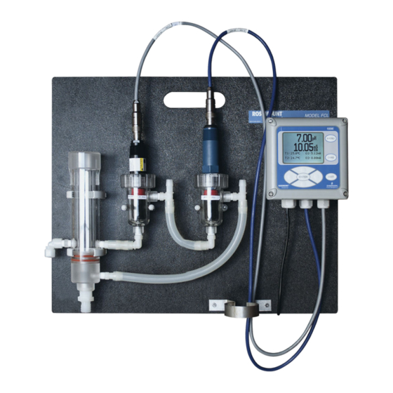
Rosemount FCL-01 (free chlorine without continuous pH correction) The Rosemount FCL-01 consists of the following items mounted on a back plate. 1. Rosemount 1056-03-24-38-AN transmitter with sensor cable attached. 2. Constant head overflow sampler with flow cell for chlorine sensor. -
Page 12: Sample Requirements
FCL is intended for wall mounting only. Refer to Figure 2-1 Figure 2-2 for details. The sensor(s) screw into the flow cell adapters as shown in the figures. For Rosemount FCL-02 (free chlorine with continuous pH adjustment), you must also install the pH sensor. Emerson.com/Rosemount... - Page 13 Reference Manual Install 00809-0100-3412 May 2019 Figure 2-1: Rosemount FCL-01 A. Chlorine sensor B. Inlet C. Drain Rosemount FCL 1056...
- Page 14 Install Reference Manual May 2019 00809-0100-3412 Figure 2-2: Rosemount FCL-02 A. pH sensor B. Chlorine sensor C. Inlet D. Drain A ¼-in. OD tubing compression fitting is provided for the sample inlet. If desired, you can remove the compression fitting and replace it with a barbed fitting. The fitting screws into a ¼-in.
-
Page 15: Install The Sensor(S)
3. Confirm that sample is flowing through the flow cells. Install the sensor(s) ™ Emerson provides the Rosemount FCL with the sensor cable pre-wired to the transmitter. Procedure 1. Connect the chlorine sensor (Rosemount 499ACL-01-54-VP) to the cable labeled 2. - Page 16 Install Reference Manual May 2019 00809-0100-3412 Figure 2-3: Rosemount FCL-01 A. Chlorine sensor B. Inlet C. Drain Emerson.com/Rosemount...
- Page 17 Reference Manual Install 00809-0100-3412 May 2019 Figure 2-4: Rosemount FCL-02 A. pH sensor B. Chlorine sensor C. Inlet D. Drain Rosemount FCL 1056...
- Page 18 Install Reference Manual May 2019 00809-0100-3412 Emerson.com/Rosemount...
-
Page 19: Chapter 3 Wire
Two analog output currents are located on the main circuit board, which is attached to the inside of the enclosure door. Figure 3-1 shows the locations of the terminals. The connectors can be detached for wiring. TB-1 is output 1. TB-2 is output 2. Polarity is marked on the circuit board. Rosemount FCL 1056... -
Page 20: Alarm Wiring
Keep output signal wiring separate from power wiring. Do not run signal and power or relay wiring in the same conduit or close together in a cable tray. Alarm wiring The alarm relay terminal strip is located just below the power connector on the power supply board. Figure 3-2. Emerson.com/Rosemount... - Page 21 Keep alarm relay wiring separate from signal wiring. Do not run signal and power or relay wiring in the same conduit or close together in a cable tray. Rosemount FCL 1056...
-
Page 22: Wire Sensor
D. Resistance temperature device sense E. Red F. Resistance temperature device in G. Clear H. Resistance temperature device shield I. +5 V out J. -4.5 V out K. Anode shield L. Orange M. Anode N. Cathode shield O. Gray P. Cathode Emerson.com/Rosemount... -
Page 23: Quick Start
1. Once connections are secured and verified, apply power to the transmitter. When the transmitter is powered up for the first time, Quick Start screens appear. Using Quick Start is easy. a. A backlit field shows the position of the cursor. Rosemount FCL 1056... - Page 24 4. Choose the desired units for chlorine. ™ The screens in Step 5 Step 6 only appear if you have a Rosemount FCL-02. 5. If you have a Rosemount FCL-01, go to Step 8. Otherwise, choose pH for Sensor 2 (S2). Emerson.com/Rosemount...
- Page 25 The main display appears. The outputs and alarms (if an alarm board is present) are assigned to default values. 10. To change outputs, alarms, and other settings, go to the Main Menu and choose Program. Follow the prompts. Rosemount FCL 1056...
- Page 26 Wire Reference Manual May 2019 00809-0100-3412 Emerson.com/Rosemount...
- Page 27 Reference Manual Wire 00809-0100-3412 May 2019 Rosemount FCL 1056...
- Page 28 Wire Reference Manual May 2019 00809-0100-3412 Emerson.com/Rosemount...
-
Page 29: Display And Operation
Figure 4-2: Programming Screen Showing Item List A. Live measurement\ B. Item list C. Arrow bar The position of the cursor is shown in reverse video. See Keypad Program the transmitter for more information. Rosemount FCL 1056... -
Page 30: Keypad
C. You are in the middle of the list. There are more items for viewing. Scroll up or down. The arrow bar shows whether additional items in a list are available. Keypad Local communication with the transmitter is through the membrane keypad. Figure 4-4 Figure 4-5 explain the operation of the keys. Emerson.com/Rosemount... - Page 31 The navigation keys are used to increase or decrease the value of a numeral. Press ENTER to select an item and store numbers and settings. Press EXIT to return to the previous screen without storing changes. Pressing MENU always causes the main menu to appear. Rosemount FCL 1056...
-
Page 32: Program The Transmitter
4 and 20 mA analog outputs. Procedure 1. Press MENU. The main Menu screen appears. There are four items in the main menu. Calibrate is in reverse video, meaning that the cursor is on Calibrate. Emerson.com/Rosemount... - Page 33 S1 is sensor 1.. The assignments shown are the defaults for the Rosemount FCL-01. Outputs are freely assignable under the Configure menu. 5. For practice, change the 20 mA settings for output 1 to 8.5 ppm .
-
Page 34: Security
There are three levels of security. 1. A user can view the default display and diagnostic screens only. 2. A user has access to the calibration and hold menus only. 3. A user has access to all menus. Emerson.com/Rosemount... -
Page 35: Using Hold
Once in hold, the sensor remains in hold until hold is turned off. However, if power is loss than restored, hold is automatically turned off. 4.5.2 Using the hold function To put the transmitter in hold, complete the following steps. Procedure 1. Press MENU. The main Menu screen appears. Rosemount FCL 1056... -
Page 36: Configure The Main Display
You can configure the main display to meet your requirements. Procedure 1. Press MENU. The main Menu screen appears. 2. Move the cursor to Display and press ENTER. The screen shows the present configuration. There are four items: Main Format, Language, Warning, and Contrast. Emerson.com/Rosemount... - Page 37 Consult the Rosemount 1056 Transmitter manual for more details. 9. Choose Language to change the language used in the display. 10. Choose Warning to disable or enable warning messages. 11. Choose Contrast to change the display contrast. Rosemount FCL 1056...
- Page 38 Display and operation Reference Manual May 2019 00809-0100-3412 12. To change the contrast, choose either lighter or darker and press ENTER. Every time you press ENTER, the display becomes lighter or darker. Emerson.com/Rosemount...
-
Page 39: Programming The Transmitter
1. Assignments (if Rosemount FCL-01) a. Output 1 Chlorine, temp Chlorine b. Output 2 Chlorine, temperature Temperature 2. Assignments (if Rosemount FCL-02) a. Output 1 Chlorine, pH, temp Chlorine b. Output 2 Chlorine, pH, temp 3. Range 0-20 or 4-20 mA 4-20 mA 4. - Page 40 0.01 d. input filter 0 to 999 sec 5 sec e. Reference impedance low or high Temperature related settings 1. Units °C or °F °C 2. Temperature compensation Automatic or manual Automatic Security code 1. Calibrate/Hold 000 to 999 Emerson.com/Rosemount...
- Page 41 0.00 to 99.99 mV/pH 59.16 mV/pH 3. User-entered offset -999 to +999 mV 0 mV Calibration - analog outputs 1. 4 mA 0.000 to 22.000 mA 4.000 mA 2. 20 mA 0.000 to 22.000 mA 20.000 mA Rosemount FCL 1056...
-
Page 42: Configuring, Ranging, And Simulating Outputs
If the transmitter detects a fault, a fault message appears in the main display. At the same time, the output current goes to the value programmed in this section. There are two output fault modes: fixed and live. Fixed means the selected output goes to the previously Emerson.com/Rosemount... - Page 43 4. Choose Configure. 5. Choose Output 1 or Output 2. The screen shows the present configuration. There are six items: Assign (S1 is sensor 1, S2 is sensor 2), Range, Scale, Dampening, Fault Mode, and Fault Value. To Rosemount FCL 1056...
- Page 44 Complete the following steps to range the outputs by assigning values to the low and high outputs. Procedure 1. Press MENU. The main Menu screen appears. 2. Move the cursor to Program and press ENTER. The cursor is on Outputs. 3. Press ENTER. 4. Choose Range. Emerson.com/Rosemount...
- Page 45 Complete the following steps to simulate an output by making the transmitter generate an output current equal to the value you enter. Procedure 1. Press MENU. The main Menu screen appears. 2. Move the cursor to Program and press ENTER. The cursor is on Outputs. 3. Press ENTER. Rosemount FCL 1056...
-
Page 46: Configuring Alarms And Assigning Setpoints
Configure the alarms first. 1. Configuring an alarm means a. Assigning a sensor and measurement (chlorine, pH, or temperature) to an alarm. An alarm relay can also be used as a timer. b. Selecting high or low logic. c. Choosing the deadband. Emerson.com/Rosemount... - Page 47 C. Deadband = 0.3 ppm D. Alarm deactivates E. Time F. High alarm setpoint The alarm activates when the chlorine concentration exceeds the high setpoint. The alarm remains activated until the reading drops below the value determined by the deadband. Rosemount FCL 1056...
- Page 48 Figure 5-3 shows how the timer operates. While the interval timer is operating, the main display, analog outputs, and assigned alarms for the sensor(s) can be put on hold. During hold, the main display remains at the last value. Emerson.com/Rosemount...
- Page 49 Selecting high or low logic. c. Choosing the deadband. d. Setting the interval timer parameters. 2. Simulating an alarm means making the transmitter energize or de-energize an alarm relay. Procedure 1. Press MENU. Rosemount FCL 1056...
- Page 50 5. Choose Alarm 1, Alarm 2, Alarm 3, or Alarm 4. The screens summarizes the present configuration and setpoints. There are eight items: • Setpoint • Assign (S1 is sensor 1 and S2 is sensor 2) • Logic • Deadband • Interval time Emerson.com/Rosemount...
- Page 51 Complete the following steps to make the transmitter energize or de-energize an alarm relay. Procedure 1. Press MENU. The main Menu screen appears. 2. Move the cursor to Program and press ENTER. 3. Choose Alarms. 4. Choose Simulate. Rosemount FCL 1056...
- Page 52 Synchronize timers Synch Timers is available only if two or more alarm relays have been configured as interval timers. Procedure 1. Press MENU. The main Menu screen appears. 2. Move the cursor to Program and press ENTER. 3. Choose Alarms. Emerson.com/Rosemount...
-
Page 53: Configuring The Measurement
4. Make various pH measurement settings. The transmitter supplied with the Rosemount FCL is designed to be as versatile as possible. The pH settings below are needed in some applications but are not used when pH is measured for the purpose of correcting free chlorine readings. - Page 54 Because the sensor responds only to HOCl, a pH correction is necessary to properly convert the sensor current into a free chlorine reading. The Rosemount FCL uses either continuous (live) or manual pH correction. In continuous (live) correction, the transmitter continuously monitors the pH of the sample and corrects the free chlorine readings for changes in pH.
- Page 55 Choose Sensor 1 (chlorine) or Sensor 2 (pH). The screen summarizes the present configuration for sensor 1 (chlorine). If you have a Rosemount FCL-02, the items are Measure, Units, Filter, Free Cl Correct, and Resolution. If you have a Rosemount FCL-01, the items are Measure, Units, Filter, Manual pH, and Resolution.
-
Page 56: Configuring Temperature Related Settings
If you have a Rosemount FCL-01, Free Cl Correct (free chlorine correction) will not appear. Instead, enter the desired pH correction value for Manual pH. - Page 57 2. Choose automatic or manual temperature correction for membrane permeability. 3. Choose automatic or manual temperature compensation for pH. 4. Enter a temperature for manual temperature compensation. Procedure 1. Press MENU. The main Menu screen appears. 2. Move the cursor to Program and press ENTER. Rosemount FCL 1056...
-
Page 58: Configuring Security Settings
What happens User enters and has access to all menus. User enters and has access to Calibration and Hold menus only. User enters and has access to all menus. User needs no security code to have access to all menus. Emerson.com/Rosemount... - Page 59 A screen appears in which the present setting can be edited. 5. Press ENTER to store a change. The security code takes effect two minutes after pressing ENTER. 6. To return to the main display, press MENU and then EXIT. Rosemount FCL 1056...
-
Page 60: Set Up Diagnostics
Glass fault high A typical glass electrode has an impedance of about 100 MΩ. As the sensor ages, glass impedance increases. Extremely high impedance (greater than about 1000 MΩ) implies the sensor is nearing the end of its life. High impedance may also mean that the sensor is not submerged in the process liquid. Emerson.com/Rosemount... -
Page 61: Resetting The Transmitter
4. To make a change, move the cursor to the desired line and press ENTER. A screen appears in which the present settings can be edited. Emerson recommends that you set the settings to the values in the table. - Page 62 (Sensor Cal Only), or output calibration (Output Cal Only). If you choose Sensor Cal Only or Output Cal Only, a second screen appears in which you can select which sensor or output calibration to reset. 5. To return to the main display, press MENU and then EXIT. Emerson.com/Rosemount...
-
Page 63: Chapter 6 Calibrate
For example, a 1 °C error causes at most an error of ±0.03 in the calculated buffer pH. Without calibration, the accuracy of the temperature measurement is about ±0.4 °C. Calibrate the sensor/transmitter unit if: Rosemount FCL 1056... -
Page 64: Calibration - Free Chlorine
Calibrating the sensor requires exposing it to a solution containing no free chlorine (zero standard) and to a solution containing a known amount of free chlorine (full-scale standard). Emerson.com/Rosemount... - Page 65 (properly calibrated) must be in the process liquid before starting the calibration. If the transmitter is using manual pH correction, be sure to enter the pH value before starting the calibration. Rosemount FCL 1056...
- Page 66 Sensor 1 is the chlorine sensor. Sensor 2 (if present) is the pH sensor. 7. Choose Free Chlorine. 8. Choose Zero Cal. The transmitter automatically starts the zero calibration. If the zero calibration was successful, the following screen appears. Emerson.com/Rosemount...
- Page 67 3. Adjust the chlorine concentration until it is near the upper end of the operating range. Wait until the transmitter reading is stable before starting calibration. 4. Press MENU. The main Menu screen appears. The cursor is on Calibrate. Rosemount FCL 1056...
- Page 68 If the calibration was successful, the live reading changes to the value entered in step 9, and the display returns to the screen in step 6. If the sensitivity is too far outside the range of expected values the following screen appears. Emerson.com/Rosemount...
-
Page 69: Calibration - Ph
1.09, 3.06, 4.65, 6.79, 9.23, 12.75 Ingold 1.993, 4.005, 7.002, 9.206 Merck 2.002, 4.014, 7.003, 9.004, 12.009 Fisher 1.00, 2.00, 3.00, 4.00, 5.00, 6.00, 7.00, 8.00, 9.00, 10.00, 11.00 With the exception of pH 7.01 buffer, the standard buffers are NIST buffers. Rosemount FCL 1056... - Page 70 Stability criteria are user- programmable. The use of automatic buffer calibration minimizes errors, and Emerson strongly recommends its use. Manual buffer In manual calibration, you must enter the pH value of the buffer at calibration the temperature of the buffer.
- Page 71 16. To make a change, move the cursor to the desired line and press ENTER. A screen appears in which the present setting can be edited. 17. Press ENTER to store the change. 18. To return to the main display, press MENU and then EXIT. Rosemount FCL 1056...
- Page 72 7. If the calibration is not successful, the existing calibration data is not changed. A screen appears identifying the error (high slope, low slope, or offset error). For troubleshooting, see Section. 17. To return to the main display, press MENU and then EXIT. Emerson.com/Rosemount...
-
Page 73: Calibration - Analog Outputs
6.5.1 Trimming analog outputs Although Emerson calibrates the analog outputs at the factory, you can trim them in the field to match the reading from a standard milliameter. You can trim both the low (0 or 4 mA) and high (20 mA) outputs 6.5.2... - Page 74 If the user entered value is more than ±1 mA different from the nominal value, a possible error screen appears. 7. To force the transmitter to accept the calibration, choose Yes. 8. To return to the main display, press MENU and then EXIT. Emerson.com/Rosemount...
-
Page 75: Chapter 7 Digital Communications
Reference Manual Digital communications 00809-0100-3412 May 2019 Digital communications The transmitter supplied with the Rosemount FCL does not have the digital communications option. Rosemount FCL 1056... - Page 76 Digital communications Reference Manual May 2019 00809-0100-3412 Emerson.com/Rosemount...
-
Page 77: Chapter 8 Maintenance
Replace sensor circuit board ™ The Rosemount 1056 transmitter used with the Rosemount FCL requires little routine maintenance. Clean the transmitter case and front panel by wiping with a clean soft cloth dampened with water only. Do not use solvents, like alcohol, that might cause a buildup of static charge. -
Page 78: Chlorine Sensor
8.2.3 Replacing the electrolyte solution and membrane WARNING HARMFUL SUBSTANCE Fill solution may cause irritation. May be harmful if swallowed. Read and follow manual. Procedure 1. Unscrew the membrane retainer. 2. Remove the membrane assembly and O-ring. Figure 8-1. Emerson.com/Rosemount... - Page 79 9. Hold the sensor at about a 45° angle with the cathode end pointing up. 10. Add electrolyte solution through the fill hole until the liquid overflows. 11. Tap the sensor near the threads to release trapped air bubbles. 12. Add more electrolyte solution if necessary. Rosemount FCL 1056...
- Page 80 O-ring, Viton 2-014 33521-00 Membrane retainer 23501-08 Free chlorine membrane assembly: includes one membrane assembly and one O-ring 23502-08 Free chlorine membrane kit: includes three membrane assemblies and three O-rings 9109536 #4 free chlorine sensor fill solution, 4 oz (120 mL) Emerson.com/Rosemount...
-
Page 81: Ph Sensor
3. Rinse the sensor thoroughly with water and soak in pH buffer for several hours. 4. Recalibrate the sensor in buffers before returning it to service. 8.3.3 Other maintenance The 3900VP-02-10 sensor supplied with the Rosemount FCL-02 is disposable. It has no replaceable parts. Constant head flow controller 8.4.1... - Page 82 Rosemount FCL-01. Table 8-3 Figure 8-3 show replacement parts for the flow controller assembly used in the Rosemount FCL-02. Table 8-2: Rosemount FCL-01 Constant Head Flow Controller Assembly Replacement Parts Location in Description Figure 8-2 24039-00 Flow cell for chlorine sensor with bubble shedding nozzle...
- Page 83 Maintenance 00809-0100-3412 May 2019 Figure 8-2: Rosemount FCL-01 Constant Head Flow Controller Assembly Replacement Parts Table 8-3: Rosemount FCL-02 Constant Head Flow Controller Assembly Replacement Parts Location in Description Figure 8-3 24039-00 Flow cell for chlorine sensor with bubble shedding nozzle...
- Page 84 Maintenance Reference Manual May 2019 00809-0100-3412 Figure 8-3: Rosemount FCL-02 Constant Head Flow Controller Assembly Replacement Parts Emerson.com/Rosemount...
-
Page 85: Chapter 9 Troubleshoot
Warnings. To read measurement information about the sensor(s), including raw sensor signal and calibration data, choose the desired sensor and press ENTER. If you choose Faults or Warnings, a screen like the one below appears. S1 means sensor 1. S2 means sensor 2. Rosemount FCL 1056... -
Page 86: Troubleshooting When A Fault Message Is Showing
Communicating Sensor CPU Error Sensor board software is corrupted. Sensor CPU Error Sensor RTD Open Temperature measuring circuit is Sensor RTD open open. S1 Not Detected No sensor board is connected to Sensor 1 Not Detected sensor 1 terminal. Emerson.com/Rosemount... - Page 87 , reset the transmitter to factory default, re-enter user settings, and repeat Data calibration. 9.3.2 Hardware error Hardware error means that there is a missing or bad hardware component on the sensor board. The board must be replaced. Rosemount FCL 1056...
- Page 88 The sensor board must be replaced. 9.3.6 Sensor RTD Open The chlorine and pH sensors used in the Rosemount FCL contain a Pt 100 RTD (resistance temperature device) for measuring temperature. Sensor RTD Open means the temperature measuring circuit is open.
- Page 89 These messages mean factory eeprom data or user eeprom data on the sensor board is corrupted or the CPU on the sensor board is bad. Procedure 1. Cycle power off and then on. 2. Replace the sensor board. Rosemount FCL 1056...
- Page 90 ™ The Rosemount 3900VP pH sensor supplied with the Rosemount FCL-02 has a porous reference junction, so the normal reference impedance is low, less than 5 kΩ. High reference impedance suggests that the junction is severely fouled, the fill solution has become depleted, or the junction is not fully submerged in the sample.
-
Page 91: Troubleshooting When A Warning Message Is Showing
9.4.1 Sensor No Solution Gnd This message implies that the pH sensor is miswired. Check sensor wiring. 9.4.2 Sensor Need Factory Cal The sensor board was improperly calibrated at the factory. Call the factory for assistance. Rosemount FCL 1056... - Page 92 3. Use a wire jumper to connect the sense and return terminals to the sensor terminal strip. The transmitter will no longer correct the temperature for lead resistance or compensate for changes in ambient temperature. The error could be several °C or more. 4. Replace the sensor. Emerson.com/Rosemount...
-
Page 93: Troubleshooting When No Error Message Is Showing
1. Is the sensor properly wired to the transmitter? See Wire sensor. 2. Is the zero solution chlorine free? Take a sample of the solution and test it for free chlorine level. The concentration should be less than about 0.02 ppm. Rosemount FCL 1056... - Page 94 4. Is the membrane fouled or coated? A dirty membrane inhibits diffusion of free chlorine through the membrane, reducing the sensor current and increasing the response time. Clean the membrane by rinsing it with a stream of water from a Emerson.com/Rosemount...
- Page 95 3. Make sure the sample flow is in the recommended range. Gradual loss of flow will cause downward drift. Be sure the liquid level in the constant head sampler is level with the central overflow tube and that excess Rosemount FCL 1056...
- Page 96 Check that the holes at the base of the cathode stem are open. Use a straightened paper clip to clear blockages. See step 4 in Zero current is unstable.. b) Replace the electrolyte solution. 5. Replace the sensor. Emerson.com/Rosemount...
-
Page 97: Troubleshooting When No Error Message Is Showing - Ph
2-2. See Constant head flow controller. Troubleshooting when no error message is showing - pH Problem See Section Calibration Error warning during two-point calibration. Calibration error during two-point calibration. Offset Error warning during standardization. Calibration error during standardization. Rosemount FCL 1056... - Page 98 Table 9-1: Glass impedance (Glass imp) less than 10 MΩ Glass bulb is cracked or broken. Sensor has failed. between 10 and 1000 MΩ Normal reading. greather than 1000 MΩ pH sensor may be nearing the end of its service life. Emerson.com/Rosemount...
- Page 99 5. Is the glass bulb cracked or broken? Check the glass electrode impedance. See Calibration error during two-point calibration.. 6. Is the transmitter working properly? Check the transmitter by simulating the pH input. See Simulate pH input. Rosemount FCL 1056...
- Page 100 Tape back the ends of the disconnected wires to keep them from making accidental connections with other wires or terminals. c) Connect a jumper wire between the RTD RETURN and RTD SENSE terminals. See the wiring diagrams in Wire sensor. Emerson.com/Rosemount...
-
Page 101: Troubleshooting When No Error Message Is Showing - General
2. Make sure the temperature element in the pH sensor is completely submerged in the test liquid. 3. Make sure the standard temperature sensor is sumberged to the correct level. 4. Review Calibrate temperature. 9.7.2 Current output too low Load resistance is too high. Maximum load is 550 Ω. Rosemount FCL 1056... -
Page 102: Simulate Inputs - Chlorine
The input current is the second line in the display. 4. Change the decade box resistance and verify that the correct current is shown. Calculate current from the equation: The voltage of a fresh 1.5 volt battery is about 1.6 volt (1600 mV). Emerson.com/Rosemount... -
Page 103: Simulate Ph Input
Set the voltage source to the value shown in the table and verify that the pH and millivolt readings match the values in the table. Voltage (mV) pH (at 25 °C) 295.8 2.00 177.5 4.00 59.2 6.00 -59.2 8.00 -177.5 10.00 -295.8 12.00 Rosemount FCL 1056... -
Page 104: Simulating Temperature
(and sometimes fourth) wire allows the transmitter to correct for the resistance of the lead wires and for changes in the lead wire resistance with temperature. 9.10.2 Simulate temperature To simulate the temperature input, wire a decade box to the transmitter as shown in Figure 9-5. Emerson.com/Rosemount... - Page 105 19.2 °C. Because the difference between the displayed temperatures (10.0 °C) is the same as the difference between the simulated temperatures, the transmitter is working correctly. Temp. (°C) Pt 100 (Ω) 100.0 103.9 107.8 109.7 111.7 115.5 119.4 Rosemount FCL 1056...
- Page 106 Troubleshoot Reference Manual May 2019 00809-0100-3412 Temp. (°C) Pt 100 (Ω) 123.2 127.1 130.9 132.8 134.7 138.5 Emerson.com/Rosemount...
- Page 107 Reference Manual 00809-0100-3412 May 2019 Rosemount FCL 1056...
- Page 108 2019 Emerson. All rights reserved. twitter.com/rosemount_news The Emerson logo is a trademark and service mark of Emerson Electric Co. Rosemount is a Facebook.com/Rosemount mark of one of the Emerson family of companies. All other marks are the property of their youtube.com/RosemountMeasurement respective owners.
Need help?
Do you have a question about the Rosemount FCL and is the answer not in the manual?
Questions and answers