Emerson Rosemount 3414 Installation Manual
Gas ultrasonic flow meters
Hide thumbs
Also See for Rosemount 3414:
- Maintenance and troubleshooting manual (96 pages) ,
- Installation manual (106 pages) ,
- Maintenance and troubleshooting manual (88 pages)

Related Manuals for Emerson Rosemount 3414


Summary of Contents for Emerson Rosemount 3414
- Page 1 Installation manual 00825-0600-3104, Rev AB January 2023 3410 Series Gas Ultrasonic Flow Meters Models 3414, 3412 and 3411...
- Page 2 Emerson employees. Emerson will not accept your returned equipment if you fail to follow Emerson procedures. Return procedures and forms are available on our web support site at www.emerson.com, or by phoning the Emerson Customer Service department.
-
Page 3: Table Of Contents
Installation manual Contents 00825-0600-3104 January 2023 Contents Chapter 1 Introduction....................... 5 1.1 Typical applications of this product..................5 1.2 Features and benefits of the 3411, 3412 and 3414 models meter........5 1.3 Acronyms, abbreviations and definitions.................6 1.4 MeterLink software........................9 ™ 1.5 Design of Rosemount 3410 series meter................ - Page 4 Contents Installation manual January 2023 00825-0600-3104 B.1 List of source codes for executable files................109 B.2 GNU General Public License....................109 B.3 GNU Lesser General Public License..................115 B.4 BSD Open Source License...................... 117 B.5 M.I.T License..........................118 B.6 Zlib License..........................119 Gas Ultrasonic Flow Meters...
-
Page 5: Chapter 1 Introduction
Installation manual Introduction 00825-0600-3104 January 2023 1 Introduction 1.1 Typical applications of this product Rosemount 3410 Series Ultrasonic Gas Flow Meters have various configurations ™ that meet a broad range of customer requirements. Each meter comes fully assembled from Rosemount. The technology can be applied to custody transfer, allocation measurement, and check metering applications such as: •... -
Page 6: Acronyms, Abbreviations And Definitions
• Ethernet access • On-board LED status indicators • Analog pressure and temperature inputs • Communication via Emerson’s AMS Device Manager and Field Communicator ™ • API Chapter 21 compliant event and data logging (gas meters) • MeterLink (a Windows - based interface software) ™... - Page 7 Installation manual Introduction 00825-0600-3104 January 2023 Acronym or abbreviation Definition C T S Clear-to-Send; the RS-232C hand shaking signal input to a transmitter indicating that it is okay to transmit data - i.e., the corresponding receiver is ready to receive data. Generally, the Request-to-Send (RTS) output from a receiver is input to the Clear-to-Send (CTS) input of a transmitter.
- Page 8 Introduction Installation manual January 2023 00825-0600-3104 Acronym or abbreviation Definition megapascal (equivalent to 10 Pascal) (pressure unit) Not Applicable normal cubic meters per hour NVRAM Non-Volatile Random Access Memory Pascal, equivalent to 1 newton per square meter (pressure unit) Pa × s Pascal Second (viscosity unit) Personal Computer Peripheral Field Connection (Board)
-
Page 9: Meterlink Software
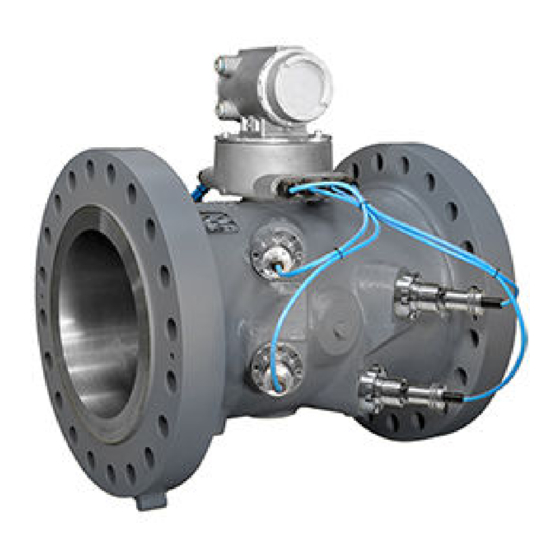
Computer simulations of various velocity profiles demonstrate that multiple measurement paths provide an optimum solution for measuring asymmetric flow. Rosemount 3414 Gas Ultrasonic Flow meters utilize four cross-bore, parallel-plane measurement paths that offer a high degree of accuracy, repeatability, bi- directional measurement and superior low-flow capabilities without the compromises associated with conventional technologies. - Page 10 Introduction Installation manual January 2023 00825-0600-3104 Figure 1-2: Rosemount 3414 Gas Ultrasonic Flow Meter design A. Transmitter electronics enclosure (explosion-proof) Optional - Local Display with glass endcap. (See Figure 1-5.) B. Base electronics enclosure (intrinsically safe) C. Meter body with transducer assemblies (T-11, T-12, T-21, T-22 or T-200)
- Page 11 Installation manual Introduction 00825-0600-3104 January 2023 Figure 1-3: Rosemount 3412 Gas Ultrasonic Flow Meter design A. Transmitter electronics enclosure (explosion-proof) Optional - Local Display with glass endcap. (See Figure 1-5.) B. Base electronics enclosure (intrinsically safe) C. Meter body with transducer assemblies (T-11, T-12, T-21 and T-22) (intrinsically safe) Rosemount 3411 Gas Ultrasonic Flow meters are single-path (two transducer) Gas Ultrasonic Flow Meter and is referred to as a bounce-path (as the signal is...
- Page 12 Introduction Installation manual January 2023 00825-0600-3104 Figure 1-4: Rosemount 3411 Gas Ultrasonic Flow Meter design A. Transmitter electronics enclosure (explosion-proof) Optional - Local Display with glass endcap. (See Figure 1-5.) B. Base electronics enclosure (intrinsically safe) C. Meter body with transducer assemblies (T-11, T-12, T-21 or T-22) (intrinsically safe) The Rosemount Gas Ultrasonic Flow Meter design is available with an optional glass endcap and a local display.
-
Page 13: Meter Specifications For 3411, 3412 And 3414 Models
Installation manual Introduction 00825-0600-3104 January 2023 The Base Electronics Enclosure that houses the Acquisition Module. Intrinsically safe transducers and cable assemblies are designed for Class 1, Division 1, Groups C and D areas without need of further protection when installed in accordance with the field wiring diagram (refer to Rosemount drawing DMC-005324 in Engineering... - Page 14 Introduction Installation manual January 2023 00825-0600-3104 Table 1-1: Rosemount models 3411, 3412 and 3414 meter specifications (part ™ Rosemount 3411, 3412 and 3414 meter specifications ™ Meter type Number of paths • 3411 Rosemount single path (two transducer) or center-line (bounce) design •...
- Page 15 Installation manual Introduction 00825-0600-3104 January 2023 Table 1-1: Rosemount models 3411, 3412 and 3414 meter specifications (part ™ (continued) Rosemount 3411, 3412 and 3414 meter specifications ™ Velocity range • 100 ft/s (30 m/s) with over-range) • 125 fps (38 m/s) on some line sizes •...
- Page 16 Introduction Installation manual January 2023 00825-0600-3104 Table 1-3: Rosemount models 3411, 3412 and 3414 meter specifications (part ™ (continued) Accuracy Limits Model 3414 accuracy limits (AGA 9 compliant) are: • ± 1% without a flow calibration (10” and smaller line sizes) •...
- Page 17 Installation manual Introduction 00825-0600-3104 January 2023 Table 1-4: Transducer specifications Transducer type Temperature range Mount and holder type T-11 -20 °C to +100 °C (-4 °F to Standard mounts/Holders, 212 °F) NBR O-ring Inconel mounts/316L Holders, NBR O-ring Inconel Mounts/Inconel Holders/FKM O-ring T-12 -20 °C to +100 °C (-4 °F to...
- Page 18 Introduction Installation manual January 2023 00825-0600-3104 Table 1-5: Rosemount models 3411, 3412 and 3414 meter specifications (part ™ Communications specifications Connectivity protocols One serial RS-232/RS-485 port (115 kbps baud rate) (Modbus RTU/ASCII) • (1) Serial Port A • (RS-232/RS-485 Full Duplex/RS-485 Half Duplex) One Ethernet Port (TCP/IP) 100 BaseT •...
- Page 19 Installation manual Introduction 00825-0600-3104 January 2023 Table 1-5: Rosemount models 3411, 3412 and 3414 meter specifications (part ™ (continued) Frequency/Digital Output(s) The meter has user-configurable selections for either a frequency output or digital status (FODO) (Also see Frequency/Digital outputs). Frequency/Digital Outputs •...
-
Page 20: Preinstallation Considerations
Introduction Installation manual January 2023 00825-0600-3104 Table 1-5: Rosemount models 3411, 3412 and 3414 meter specifications (part ™ (continued) Phase A and Phase B output (based on flow direction) • Reverse flow - output only reports flow in the reverse direction. For frequency outputs, Phase B of the output is 90 degrees out of phase with Phase A. -
Page 21: Safety Considerations
Installation manual Introduction 00825-0600-3104 January 2023 • Data collection and retention procedures 1.8 Safety considerations The Rosemount 3410 Series Gas Ultrasonic Flow Meter is suitable for use in U.L. ™ Class 1, Division 1, Group C and D hazardous locations. NOTICE An “X”... -
Page 22: Certifications And Approvals For The Rosemount ™ 3410 Series
• NEPSI • GOSTR Important Please consult Emerson Flow services for Rosemount products for the complete metrology approvals list. 1.10 FCC compliance This equipment has been tested and found to comply with the limits for a Class A digital device, pursuant to Part 15 of the FCC Rules. These limits are designed to provide reasonable protection against harmful interference when the equipment is operated in a commercial environment. -
Page 23: References
Installation manual Introduction 00825-0600-3104 January 2023 residential area is likely to cause harmful interference in which case the user will be required to correct the interference at his own expense. NOTICE Changes or modifications not expressly approved by the party responsible for compliance could void the user's authority to operate the equipment. - Page 24 Introduction Installation manual January 2023 00825-0600-3104 Gas Ultrasonic Flow Meters...
-
Page 25: Chapter 2 Mechanical Installation
Installation manual Mechanical installation 00825-0600-3104 January 2023 2 Mechanical installation 2.1 Meter piping, lifting and mounting Refer to the following sections for piping recommendations, lifting with hoist rings and slings, mounting in heated or cooled pipelines and safety warnings and precautions. - Page 26 Mechanical installation Installation manual January 2023 00825-0600-3104 WARNING CRUSHING HAZARD Do not remove flange stabilizers. Attempting to do so could allow the meter to roll, resulting in serious injury or equipment damage. A. Flange stabilizers WARNING CRUSHING HAZARD Before installation, do not rest the meter on a slope of greater than 10 degrees. Also ensure the surface is solid so that the flange stabilizers do not sink into the surface.
-
Page 27: Meter Components
Failure to select the suitable meter seals may cause escaping gases or liquids, resulting in injury or equipment damage. Consult your Emerson Flow sales and service representative to ensure you purchase the correct components and seals for your application. 2.2 ... - Page 28 Mechanical installation Installation manual January 2023 00825-0600-3104 WARNING CONTENTS MAY BE HAZARDOUS The meter must be fully depressurized and drained before attempting to remove the T-200 transducer assembly. If gas or fluid begins to leak from the T-200 transducer stalk assembly, stop immediately and reinstall T-200 stalk assembly. Failure to comply could cause serious injury or equipment damage.
- Page 29 Installation manual Mechanical installation 00825-0600-3104 January 2023 Figure 2-1: Rosemount 3414 Flow Meter assembly A. Explosion-proof transmitter enclosure (CPU Module, Power Supply, I.S. Barrier Board B. Intrinsically-safe base enclosure includes Acquisition Module C. Meter - body and transducer assemblies and cables D.
- Page 30 Mechanical installation Installation manual January 2023 00825-0600-3104 Figure 2-2: Rosemount 3412 Flow Meter assembly A. Explosion-proof transmitter enclosure (CPU Module, Power Supply, I.S. Barrier Board, Backplane board) - (Optional: glass endcap for Local Display) B. Intrinsically-safe base enclosure includes Acquisition Module C.
- Page 31 Installation manual Mechanical installation 00825-0600-3104 January 2023 Figure 2-3: Rosemount 3411 Flow Meter assembly A. Explosion-proof transmitter enclosure (CPU Module, Power Supply, I.S. Barrier Board, Backplane board) - (Optional: glass endcap for Local Display) B. Intrinsically-safe base enclosure includes Acquisition Module C.
-
Page 32: Pipe Recommendations
Mechanical installation Installation manual January 2023 00825-0600-3104 2.3 Pipe recommendations WARNING BURST HAZARD Before pipeline cleaning and maintenance ("pigging operations"), remove straightening vanes or flow conditioners. Failure to do so may cause excessive pressure in the meter system, resulting in serious injury/death or equipment damage. - Page 33 Installation manual Mechanical installation 00825-0600-3104 January 2023 NOTICE For optimal flow measurement conditions, Rosemount suggests the piping ™ configurations below. Regardless of the configuration selected, the user agrees to accept full responsibility for the site piping design and installation. Flow conditioning is recommended for best measurement results •...
-
Page 34: Pre-Installation Inspection
P = Pressure measurement location • T = Temperature measurement location NOTICE Refer to the ultrasonic flow meter product datasheets: (www.emerson.com). • Rosemount 3410 Series Ultrasonic Gas Flow Meters should be mounted in horizontal piping with the chord paths horizontal. - Page 35 1. Ensure flange sealing faces are undamaged. 2. Movement of components that should be rigid. If any damage is found, contact Emerson Flow services before putting meter into service. Refer to the Emerson Flow services contact information on the back cover of this manual.
- Page 36 Mechanical installation Installation manual January 2023 00825-0600-3104 • Using appropriately rated lifting slings positioned at designated areas of the Rosemount Ultrasonic Meter. Both methods must be used in conjunction with all appropriate company hoisting and rigging standards or the DOE-STD-1090-2004 HOISTING AND RIGGING standard if such company standards do not exist.
- Page 37 Installation manual Mechanical installation 00825-0600-3104 January 2023 Figure 2-11: Safety approved hoist ring Figure 2-12: Non-compliant eye bolt Safety precautions using safety engineered swivel hoist rings Read and follow the Safety Precautions listed below. Procedure 1. Meters must only be lifted by personnel properly trained in the safe practices of rigging and lifting.
- Page 38 Mechanical installation Installation manual January 2023 00825-0600-3104 4. Use only the safety engineered swivel hoist rings that are rated for lifting the meter. Do not use any other type of hoist rings with the same screw size or heavy duty hoist rings. The meter tapping and counter bore size are suitable only for the hoist rings specified by Rosemount ™...
- Page 39 Installation manual Mechanical installation 00825-0600-3104 January 2023 precautions using appropriate rated lifting slings). If the slings do come in contact with the electronic enclosure, then remove the two bolts holding the enclosure to its base and temporarily remove the head from the meter during the lifting operation.
- Page 40 Mechanical installation Installation manual January 2023 00825-0600-3104 12. NEVER lift more than the ultrasonic meter assembly including electronics and transducers with the hoist rings. The only exception that safe is to lift the meter with one ASME B16.5 or ASME B16.47 blind flange bolted to each end flange of the meter.
- Page 41 Installation manual Mechanical installation 00825-0600-3104 January 2023 Table 2-2: Hoist Ring Lookup Table for Rosemount 3414 Gas Meters ANSI 300 ANSI 600 ANSI 900 ANSI 1500 Rosemount Part Number 4” to 10” 4” to 8” 4” to 8” 4” to 6”...
- Page 42 Mechanical installation Installation manual January 2023 00825-0600-3104 Figure 2-15: Correct sling attachment 4. Visually inspect the slings prior to use for any signs of abrasion or other damage. Refer to the sling manufacturer's procedures for proper inspection of the particular sling you are using. 5.
-
Page 43: Mounting Requirements In Heated Or Cooled Pipelines
Installation manual Mechanical installation 00825-0600-3104 January 2023 Figure 2-16: Incorrect sling attachment 8. NEVER apply shock loads to the meter. Always lift the meter gradually. If shock loading ever occurs, the slings must be inspected per manufacturer's procedures prior to being placed in any further service. 2.5 ... - Page 44 Mechanical installation Installation manual January 2023 00825-0600-3104 transducers have an operating range from -58 °F (-50 °C) to 212 °F (+100 °C). T-200 transducers have an operating range from -58 °F (-50 °C) to 257 °F (+125 °C). CAUTION SURFACE TEMPERATURE HAZARD The meter body and piping may be extremely hot or cold.
-
Page 45: Chapter 3 Electrical Installation
Installation manual Electrical installation 00825-0600-3104 January 2023 3 Electrical installation 3.1 Cable length TTL mode The maximum cable length is 2000 feet when the Digital Output “TTL” mode is selected. 3.2 Cable length Open Collector mode For the Digital Output “open collector” mode, the maximum cable length depends on the cable parameters, pull-up resistance used, the maximum frequency to output, and frequency input parameters being driven. -
Page 46: Grounding Meter Electronics Housing
Electrical installation Installation manual January 2023 00825-0600-3104 • Resistance = 0.0168 Ohms/ft or 16.8 Ohms/1000 ft • Pull-up voltage = 24 VDC 3.3 Grounding meter electronics housing The meter electronics should be internally grounded for intrinsically safe operations. Connect a wire to the chassis ground lug installed inside the Transmitter Electronics Enclosure as the primary ground. -
Page 47: Conduit Seals
Installation manual Electrical installation 00825-0600-3104 January 2023 Figure 3-2: External ground lug A. External ground lug 3.4 Conduit seals Conduit seals are required for meter installations in hazardous environments. Adhere to safety instructions to protect personnel and equipment. WARNING EXPLOSION HAZARD To reduce the risk of an explosion or fire, conduit runs must have a sealing fitting connected within 457.2 mm (18 inches) of the enclosure. - Page 48 Electrical installation Installation manual January 2023 00825-0600-3104 3.4.1 Startup for systems that use explosion-proof conduit Procedure 1. Assemble conduit to the Transmitter Electronics Enclosure. A conduit seal fitting is required within 18 inches (457 mm) of the enclosure. 2. Check to make certain that all power to field wiring is turned OFF. WARNING HAZARDOUS VOLTAGE INSIDE Do not open the Transmitter Electronics Enclosure when an explosive gas...
- Page 49 Installation manual Electrical installation 00825-0600-3104 January 2023 Figure 3-3: Electronics field wiring - upper terminal block, switches, ground lug - Type 2 CPU Module A. Conduit wiring entry (four entries) c. Analog In B. Switches: • Analog In (AI1) 1. Port A —...
- Page 50 Electrical installation Installation manual January 2023 00825-0600-3104 Figure 3-4: Transmitter electronics field wiring lower terminal block - Type 2 CPU Module A. Lower Terminal Block d. Ethernet a. FODO Group 1 connections • Ethernet (orange and white wire) • FODO1 •...
- Page 51 Installation manual Electrical installation 00825-0600-3104 January 2023 Figure 3-5: Electronics field wiring - upper terminal block, switches, ground lug - Type 4CPU Module A. Conduit wiring entry (four entries) b. Analog In B. Switches: • Analog In (AI1) 1. Port A —...
- Page 52 Electrical installation Installation manual January 2023 00825-0600-3104 Figure 3-6: Transmitter electronics field wiring lower terminal block - Type 4 CPU Module A. Lower Terminal Block d. Ethernet a. FODO Group 1 connections • Ethernet (orange and white wire) • FODO1 •...
- Page 53 Installation manual Electrical installation 00825-0600-3104 January 2023 3410 Series engineering drawings), MeterLink Software for Gas and Liquid Ultrasonic Meters Quick Start Manual (00809-0100-7630) and use the MeterLink Field Setup Wizard to complete the configuration. 7. Verify the field connections are working correctly. Allow the system to run for the time specified by the customer (usually one week) and an electrician has fully tested the connections.
-
Page 54: Wiring And Inputs/Outputs
Electrical installation Installation manual January 2023 00825-0600-3104 9. If required, install the wire seals through the socket head bolts on the Base Enclosure (see Security seal installation, Figure 3-22 Figure 3-23). 10. Re-apply electrical power to the system. 3.5 Wiring and inputs/outputs MeterLink uses the TCP/IP protocol to communicate with the Rosemount 3410 ™... - Page 55 Installation manual Electrical installation 00825-0600-3104 January 2023 Figure 3-7: CPU Module labeling and LED indicators - Type 2 A. Acquisition/Measurement mode B. Power C. LED 5 - communication between CPU and Acquisition Module D. LED 4 - link between CPU and Acquisition Module E.
- Page 56 Electrical installation Installation manual January 2023 00825-0600-3104 Table 3-2: CPU Module labeling and LED functions CPU Module Function Switch position indicator or LED label or LED WRITE PROT. Switch position • Write-protect mode - with switch in the ON position •...
- Page 57 Installation manual Electrical installation 00825-0600-3104 January 2023 Table 3-2: CPU Module labeling and LED functions (continued) CPU Module Function Switch position indicator or LED label or LED PORT A Switch position • PORT A override - RS-232 serves as an override during •...
- Page 58 Electrical installation Installation manual January 2023 00825-0600-3104 Ethernet communications The Ethernet port IP address, subnet mask, and gateway address are software- configurable. In addition, a meter can be configured to act as a DHCP (Dynamic Host Configuration Protocol) server to assign an IP address to a PC or laptop running MeterLink.
- Page 59 Installation manual Electrical installation 00825-0600-3104 January 2023 A DIN 41612 48-pin connector is the interface from the CPU Module to the Field Connection Board (male end located on the back of the Field Connection Board). Cybersecurity and network communications The 3410 electronics TCP/IP communications should be configured to mitigate cybersecurity risks as follows: 1.
- Page 60 Electrical installation Installation manual January 2023 00825-0600-3104 selecting this option, you can also enable Modbus TCP communications on a secondary TCP port specified by Alternate Modbus TCP port. Alternate Modbus TCP port: Enter the alternate TCP port number here after selecting Enable alternate modbus TCP port.
- Page 61 Installation manual Electrical installation 00825-0600-3104 January 2023 Table 3-4: Serial Port A parameters Port/ Description Common features Communicatio Port A • Typically used for general • Communications via MeterLink (Standard) communications with a flow using RS-232 or RS-485 Full computer, RTU (Modbus slave) Duplex •...
- Page 62 Electrical installation Installation manual January 2023 00825-0600-3104 Figure 3-9: PC to meter serial connection wiring 3.5.2 Input/output connections The Rosemount 3410 Series Gas Ultrasonic Flow Meter provides the I/O ™ connections on the CPU Module. Figure 3-10: CPU Module I/O connections A.
- Page 63 Installation manual Electrical installation 00825-0600-3104 January 2023 Figure 3-11: CPU Module I/O connections - Type 4 A. Frequency/Digital Output 2 B. Frequency/Digital Output 3 C. Frequency/Digital Output 4 D. Frequency/Digital Output 5 E. Analog Input - Temperature and pressure connections Optional input and output modules These modules are plugged into the second or third slot (retrofit) on the electronics head.
- Page 64 Electrical installation Installation manual January 2023 00825-0600-3104 Figure 3-12: Optional module RS-232 A. Serial COMs (RS-232) B. RS-232: RTS, TX, RX Gas Ultrasonic Flow Meters...
- Page 65 Installation manual Electrical installation 00825-0600-3104 January 2023 Figure 3-13: Optional module RS-485 A. Serial COMs (RS-485) B. RS-485: TX+, TX- (2-wire Half Duplex) Installation manual...
- Page 66 Electrical installation Installation manual January 2023 00825-0600-3104 Figure 3-14: Optional Expansion I/O Module A. Expansion I/O Module B. RS-232: RX, TX, COM/RS-485: TX+, TX- (2-wire Half Duplex) C. 4-20 mA Input - AI3+/- (future use) D. Port Ethernet switch A. D1. Port 1 B.
- Page 67 Installation manual Electrical installation 00825-0600-3104 January 2023 Table 3-5: Expansion I/O to RJ45 wiring Ethernet communication Wire color CPU/EXP White w/Green Stripe Solid Green White w/Orange stripe Solid orange Note Wiring colors for TX+/TX- and RX+/RX- can be switched as ethernet ports will automatically detect crossover vs.
- Page 68 Electrical installation Installation manual January 2023 00825-0600-3104 Table 3-6: Optional modules parameters Description Common features Port B/Port C • Typically used for general • Communications via MeterLink (Optional communications with a flow using RS-232 module) computer, RTU (Modbus slave) • Software configurable Modbus and radios.
- Page 69 Installation manual Electrical installation 00825-0600-3104 January 2023 D. Ethernet switch port 3 - Link/Activity Flashing (Green) indicator Table 3-7: Expansion I/O LED functions Expansion I/O Module LED Function TX/RX RX/TX signal (Port B/C for • Flashing Orange - RX RS485 or RS232 •...
- Page 70 Electrical installation Installation manual January 2023 00825-0600-3104 • Digital output 1B is based on Digital output1B content (Frequency Output 1Validity and Flow Direction) • Digital output 2A is based on Digital output 2A content (Frequency Output 1Validity and Flow Direction) •...
- Page 71 Installation manual Electrical installation 00825-0600-3104 January 2023 • Absolute - output reports flow in both directions. For frequency outputs, Phase B of the output is 90 degrees out of phase with Phase A. • Bidirectional - output reports flow on Phase A only in the forward direction and on Phase B only in the reverse direction.
- Page 72 Electrical installation Installation manual January 2023 00825-0600-3104 Figure 3-17: CPU Module - Frequency/Digital outputs common ground - Type A. FODO1 and Digital input1 - shared common ground (Group 1) B. FODO2 and FODO3 - shared common ground (Group 2) Figure 3-18: CPU Module - Frequency/Digital outputs common ground - Type A.
- Page 73 Installation manual Electrical installation 00825-0600-3104 January 2023 Analog input settings The Rosemount 3410 Series Gas Ultrasonic Flow Meter has the capability to ™ sample analog temperature (Analog Input 1) and pressure (Analog Input 2) with 4-20 mA signals. These analog input signals are configured to sink. The two independent analog input circuits are configured for conventional 4-20 mA service.
-
Page 74: Security Seal Installation
Electrical installation Installation manual January 2023 00825-0600-3104 Table 3-9: Configuration protect switch settings CPU Module switch Configuration Configuration protected unprotected ON (default setting) External power source connection and fuse Located inside the Transmitter Electronics Enclosure is a connector for a user- provided external power source, a 2 Amp fuse and a 24 V loop power connection for ultrasonic meter analog outputs, temperature transmitter or pressure transmitter devices. - Page 75 Installation manual Electrical installation 00825-0600-3104 January 2023 Figure 3-20: Transmitter electronics enclosure security latch A. Transmitter Electronics Enclosure end cap. Optional glass endcap for Local Display B. Security latch Procedure 1. Rotate the end cap clockwise fully closing and compressing the end cap seal.
- Page 76 Electrical installation Installation manual January 2023 00825-0600-3104 Figure 3-21: Transmitter Electronics Enclosure security seals A. Transmitter Electronics Enclosure end cap B. Security wire seals 3. Adjust the security wire, removing all slack and thread into the lead seal. 4. Crimp lead seal and cut wire ends to remove excess wire. 3.6.2 ...
- Page 77 Installation manual Electrical installation 00825-0600-3104 January 2023 Figure 3-22: Base Enclosure wire seal installation A. Base Enclosure cover B. Security wire seals 2. Position the wire to prevent counterclockwise rotation of the screws when the seal wire is taut. 3. Feed the security wire beneath the Transmitter Electronics Enclosure and through the adjacent socket head screw.
- Page 78 Electrical installation Installation manual January 2023 00825-0600-3104 Figure 3-23: Base Enclosure security seals A. Transmitter Electronics Enclosure B. Security wire seals C. Transmitter Electronics endcap security latch D. Base Enclosure 4. Cut wire ends to remove excess wire. 3.6.3 Transducer assembly security seals Use the following instructions and Figure 3-24 to install the security seal wire on...
-
Page 79: Sealing The Unit
Installation manual Electrical installation 00825-0600-3104 January 2023 Figure 3-24: Transducer assembly security seal A. Transducer cable nut B. Transducer cable connector C. Security wire seal 3.7 Sealing the unit The unit should be properly sealed with a sealing compound after electrical connections have been tested according to the customer's Best Practices schedule. - Page 80 Electrical installation Installation manual January 2023 00825-0600-3104 Gas Ultrasonic Flow Meters...
-
Page 81: Chapter 4 Configuration
Installation manual Configuration 00825-0600-3104 January 2023 4 Configuration After the mechanical and electrical installation is complete use the following to install MeterLink in order to establish connection with the meter to perform final ™ configuration and verify meter performance. 4.1 Set up the MeterLink ™... - Page 82 Configuration Installation manual January 2023 00825-0600-3104 Note Frequency outputs 1 and Digital outputs 1 are paired together meaning the Digital outputs 1 will report the status for the parameter for Frequency outputs 1. Similarly, Frequency outputs 2 and Digital outputs 2 are paired together.
- Page 83 Installation manual Configuration 00825-0600-3104 January 2023 a) Click Next to continue to the Gas Chromatograph Setup page. 10. Select the settings below to configure USM device as a Modbus Master to poll a gas chromatograph. • Port: select which serial port will be connected to the GC. While the port is configured for communications to a GC, it will not act as a Modbus slave device for communications from MeterLink or a SCADA system.
- Page 84 Configuration Installation manual January 2023 00825-0600-3104 • Volumetric gross heating value and reference temperature • Molar density reference temperature and pressure • Flow Mass density, flow compressibility and Base compressibility • Gas composition inputs - components and mole percent a) Click Next to continue to the Continuous Flow Analysis page, if View Continuous Flow Analysis setup was selected on the Startup page.
- Page 85 Installation manual Configuration 00825-0600-3104 January 2023 Table 4-1: Local display labels, descriptions and valid units (continued) Local display labels, descriptions and valid units • -ACF – Actual Cubic Feet • -ACM – Actual Cubic Meters • -MACF – Thousand Actual Cubic Feet •...
- Page 86 Configuration Installation manual January 2023 00825-0600-3104 Table 4-1: Local display labels, descriptions and valid units (continued) Local display labels, descriptions and valid units TDYVL — Current days reverse corrected volume • -SCF – Standard Cubic Feet • -SCM – Standard Cubic Meters •...
- Page 87 Installation manual Configuration 00825-0600-3104 January 2023 Table 4-1: Local display labels, descriptions and valid units (continued) Local display labels, descriptions and valid units • DEGF – Degrees Fahrenheit • DEGC – Degrees Celsius PRESS — Flow-condition pressure • PSI – Pound per square inch •...
-
Page 88: Using Ams Device Manager To Configure The Meter
This procedure assumes you have AMS Device Manager installed on the host computer and have downloaded the latest Rosemount Gas Ultrasonic Meter ™ Device Description (DD). If not installed, click the link below to download the AMS device installation tool kit. www.emerson.com/en-us/documents-and-drawings Gas Ultrasonic Flow Meters... - Page 89 3410 Series Gas Ultrasonic Flow Meter. ™ 2. Use the Filter Results By categories to narrow-down your search. a) Select the check box for HART under Communication Protocol. b) Search and select the option Emerson Rosemount Industries under ™ the Brand/Manufacturer category.
- Page 90 Configuration Installation manual January 2023 00825-0600-3104 Figure 4-2: AMS file download options 4. Click the Save button to complete the file download. Figure 4-3: AMS file download complete 5. Click Open or Open Folder to view the downloaded files. Gas Ultrasonic Flow Meters...
- Page 91 Installation manual Configuration 00825-0600-3104 January 2023 6. Establish power to the meter and wiring to Analog Output 1 for HART communication. 7. Start the AMS Device Manager using a laptop or PC. 8. Enter login credentials and click OK to launch the application. 9.
- Page 92 Configuration Installation manual January 2023 00825-0600-3104 Figure 4-5: AMS Device Manager - Overview 4.3.2 AMS Device Manager - Guided setup The Guided setup wizard provides configuration parameter settings for the meter. The Guided Setup is a subset of the Manual Setup parameters. Figure 4-6: AMS Device Manager - Guided Setup Gas Ultrasonic Flow Meters...
- Page 93 Installation manual Configuration 00825-0600-3104 January 2023 Note Before writing configuration changes to your meter, ensure you have saved the Configuration file and Maintenance log. Procedure 1. Disable the Write Protect switch in the CPU Module to write any of the following configuration parameters to your meter.
- Page 94 Configuration Installation manual January 2023 00825-0600-3104 c) Click the Frequency and Digital Output 2 tab and repeat Step 3b configure Frequency and Digital Output 2 parameters. 5. Click Setup HART to configure the HART parameters (tag, date, descriptor, message text, Final Assembly number, Poll address and number of response preambles are displayed).
- Page 95 Installation manual Configuration 00825-0600-3104 January 2023 10. Click Display Meter K-Factors from the Overview window. K-Factors are a read-only values calculated from the Full scale volumetric flow rate used with frequency outputs and the Maximum frequency for frequency output. Figure 4-8: Display Meter K-Factors 11.
- Page 96 Configuration Installation manual January 2023 00825-0600-3104 Figure 4-9: AMS Device Manager - Configure Manual Setup Procedure 1. Remove security wires from the endcap and the Bracket/Cover hex head bolts that secures the Base Enclosure if they are installed. 2. Disable the Write Protect switch in the CPU Module to write any of the following configuration parameters to your meter.
- Page 97 Installation manual Configuration 00825-0600-3104 January 2023 Note If changes are made to any Source variable on this page, apply the changes and navigate to the Guided Setup page. Navigate back to the Manual Setup for the changes to be reflected in other Manual Setup pages). a) Click Apply, after you enter the data to write the parameters to the meter.
- Page 98 Configuration Installation manual January 2023 00825-0600-3104 Figure 4-10: Gating configuration parameter Edge gated, active high — Edge gated, active low Figure 4-11: Gating configuration parameter Edge gated, active — State gated, active high Figure 4-12: Gating configuration parameter State gated, active high —...
- Page 99 Installation manual Configuration 00825-0600-3104 January 2023 Figure 4-13: Gating configuration parameter State gated, active 13. Click the Alert Setup tab (from the main Configuration page). Figure 4-14: Configure Flow Analysis Alert 14. Click the Flow Analysis tab to select Configure Reverse Flow Detection, if desired.
- Page 100 Configuration Installation manual January 2023 00825-0600-3104 c) Click the Set Flow Range Limits button and enter a positive value for the Flow Analysis Lower Velocity Range and the Upper Velocity Range Limits. When the velocity is outside of the limit parameters, an alert is triggered.
- Page 101 Installation manual Configuration 00825-0600-3104 January 2023 Figure 4-16: Configuration changes dialog c) Click the Service Tools → Variables tab. The Variables page displays tabs for the device’s Flow Data, Path Information, Flow Totals, and All Variables. Figure 4-17: AMS Device Manager - Service Tools The Service Tools → Flow Data page includes charts for flow and sound velocities.
- Page 102 Configuration Installation manual January 2023 00825-0600-3104 d) Click Service Tools → Variables → Path Information tab to view the device’s chord performance (%), Gain (dB), SNR (dB), Signal (mV) and Noise (mV). e) Click Service Tools → Variables → Flow Totals to view the volume totals (forward and reverse Uncorrected Volume) parameters for the connected device.
- Page 103 Installation manual Configuration 00825-0600-3104 January 2023 Figure 4-19: AMS Device Manager - Service Tools Trends Primary and Secondary variables display real-time uncorrected volume flow rate trends. The third and fourth variables charts displays trends for temperature and pressure. 16. Click the Service Tools → Routine Maintenance tab. Click Analog Output 1 Trim to perform a digital to analog trim adjustment of the first milliampere output.
-
Page 104: Using A Field Communicator To Configure The Meter
00825-0600-3104 4.4 Using a Field Communicator to configure the meter Prerequisites • Emerson Field Communicator software, license, installation guide and user manual available on the Emerson Field Communicator website: www.emerson.com/en-us/automation/asset-performance-management/field- device-management/field-communicators • Rosemount HART Device Description (HART DD) installed for the meter ™... - Page 105 Installation manual Configuration 00825-0600-3104 January 2023 Figure 4-20: 3414 transmitter field wiring conduit entries A. Field wiring conduit entries (4) 5. Wire Analog Input 1 (AI1) and Analog Output 1 (AO1) as shown in Figure 4-21 Engineering drawings, drawing DMC-005324. Figure 4-21: Field Communicator wiring diagram for the 3410 Series electronics 6.
-
Page 106: Security Seals For The Meter (Optional)
Configuration Installation manual January 2023 00825-0600-3104 • Diagram Page 1 - 3410 Series Root Menu; Overview, Configure → Manual Setup • Diagram Page 2 - Configure → Manual Setup (continued) and Alerts Setup • Diagram Page 3 - Service Tools → Alerts and Variables • Diagram Page 4 - Service Tools → Variables (continued), Service Tools → ... -
Page 107: Appendix A Engineering Drawings
Installation manual Engineering drawings 00825-0600-3104 January 2023 A Engineering drawings A.1 3410 Series engineering drawings This appendix contains the following engineering drawing(s) for the ultrasonic meter: DMC-005324 Rosemount 3410 Series Ultrasonic Gas Flow Meter ™ System Wiring Diagram Installation manual... - Page 108 Engineering drawings Installation manual January 2023 00825-0600-3104 Gas Ultrasonic Flow Meters...
-
Page 109: Appendix B Open Source Licenses
B.1 List of source codes for executable files For a copy of the source code covered under the open source licenses indicated in this appendix, please contact flow.support@emerson.com. B.2 GNU General Public License For more details about GNU GPL (General Public License), follow the link below: www.gnu.org... - Page 110 Open source licenses Installation manual January 2023 00825-0600-3104 To protect your rights, we need to make restrictions that forbid anyone to deny you these rights or to ask you to surrender the rights. These restrictions translate to certain responsibilities for you if you distribute copies of the software, or if you modify it.
- Page 111 Installation manual Open source licenses 00825-0600-3104 January 2023 2. You may modify your copy or copies of the Program or any portion of it, thus forming a work based on the Program, and copy and distribute such modifications or work under the terms of Section 1 above, provided that you also meet all of these conditions: a) You must cause the modified files to carry prominent notices stating that you changed the files and the date of any change.
- Page 112 Open source licenses Installation manual January 2023 00825-0600-3104 distribution and only if you received the program in object code or executable form with such an offer, in accord with Subsection b above.) The source code for a work means the preferred form of the work for making modifications to it.
- Page 113 Installation manual Open source licenses 00825-0600-3104 January 2023 It is not the purpose of this section to induce you to infringe any patents or other property right claims or to contest validity of any such claims; this section has the sole purpose of protecting the integrity of the free software distribution system, which is implemented by public license practices.
- Page 114 Open source licenses Installation manual January 2023 00825-0600-3104 CONSEQUENTIAL DAMAGES ARISING OUT OF THE USE OR INABILITY TO USE THE PROGRAM (INCLUDING BUT NOT LIMITED TO LOSS OF DATA OR DATA BEING RENDERED INACCURATE OR LOSSES SUSTAINED BY YOU OR THIRD PARTIES OR A FAILURE OF THE PROGRAM TO OPERATE WITH ANY OTHER PROGRAMS), EVEN IF SUCH HOLDER OR OTHER PARTY HAS BEEN ADVISED OF THE POSSIBILITY OF SUCH DAMAGES.
-
Page 115: Gnu Lesser General Public License
Installation manual Open source licenses 00825-0600-3104 January 2023 Ty Coon, President of Vice This General Public License does not permit incorporating your program into proprietary programs. If your program is a subroutine library, you may consider it more useful to permit linking proprietary applications with the library. If this is what you want to do, use the GNU Library General Public License instead of this License. - Page 116 Open source licenses Installation manual January 2023 00825-0600-3104 If you modify a copy of the Library, and, in your modifications, a facility refers to a function or data to be supplied by an Application that uses the facility (other than as an argument passed when the facility is invoked), then you may convey a copy of the modified version: "a) under this License, provided that you make a good faith effort to ensure that,...
-
Page 117: Bsd Open Source License
Installation manual Open source licenses 00825-0600-3104 January 2023 e) Provide Installation Information, but only if you would otherwise be required to provide such information under section 6 of the GNU GPL, and only to the extent that such information is necessary to install and execute a modified version of the Combined Work produced by recombining or relinking the Application with a modified version of the Linked Version. -
Page 118: M.i.t License
Open source licenses Installation manual January 2023 00825-0600-3104 • Redistribution and use in source and binary forms, with or without modification, are permitted provided that the following conditions are met: — Redistributions of source code must retain the above copyright notice, this list of conditions and the following disclaimer. -
Page 119: Zlib License
Installation manual Open source licenses 00825-0600-3104 January 2023 B.6 Zlib License Copyright (C) 1995-2005 Jean-loup Gailly and Mark Adler This software is provided 'as-is', without any express or implied warranty. In no event will the authors be held liable for any damages arising from the use of this software. - Page 120 Emerson Terms and Conditions of Sale are available upon request. The Emerson logo is a trademark and service mark of Emerson Electric Co. Rosemount is a mark of one of the Emerson family of companies. All other marks are the property of their respective owners.
Need help?
Do you have a question about the Rosemount 3414 and is the answer not in the manual?
Questions and answers