
Subscribe to Our Youtube Channel
Related Manuals for Timeguard LEDPRORFKB


Summary of Contents for Timeguard LEDPRORFKB
- Page 1 Dedicated PIR Light Controller c/w RF remote control for LEDPRO Floodlights Model: LEDPRORFKB – Black Model: LEDPRORFKWH – White Model: LEDPROFOB RF Remote Fob...
-
Page 2: General Information
1. General Information These instructions should be read carefully and retained for further reference and maintenance. 2. Safety • Before installation or maintenance, ensure the mains supply to the PIR sensor is switched off and the circuit supply fuses are removed or the circuit breaker turned off. - Page 3 • Motion Detection Range: Up to 12m distance at a 2.5m mounting height • Maximum Switchable Load; 140W LED Lighting 1000W Halogen Lighting 200W CFL Lighting 500W Fluorescent tube w/o PF correction • Time ON Adjustment: 3 seconds – 18 minutes •...
-
Page 4: Pack Contents
• CE Compliant • Dimensions (H x W x D): 60 x 38 x 15mm 4. Pack contents • 1x LEDPRORFKB-WH Dedicated PIR Light Controller c/w RF remote control for LEDPRO Floodlights • 1x LEDPROFOB RF Remote Fob • 1x Instruction Manual •... - Page 5 • A moving human body needs to cross/enter one of these zones to activate the light controller. The best all-round coverage is achieved with the unit mounted at the optimum height of 2.5 metres. • Careful positioning of the light controller will be required to ensure optimum performance (see diagram A detailing detection range and direction).
-
Page 6: Installation
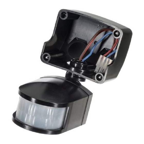
• During extreme weather conditions the motion light controller may exhibit unusual behaviour. This does not indicate a fault with the light controller. Once normal weather conditions return, the light controller will resume normal operation. 6. Installation 6.1 Ensure the mains supply is switched off and the circuit supply fuses are removed or the circuit breaker turned off. - Page 7 6.3 Remove the jumper plug from the floodlight. 6.4 Pass the 230V 50Hz mains supply and load cables the holes provided on the PIR ensuring that a cable gland, grommet or sealing compound is used to maintain the IP rating. 6.5 Terminate the cables into the terminal block ensuring correct polarity is observed and that all bare conductors are sleeved (See section 7.
- Page 8 6.7 Connect the 3 way PIR plug, by pushing the plug and socket inside the floodlight together until they lock. DO NOT FORCE. THE PLUG AND SOCKET WILL ONLY FIT TOGETHER ONE WAY AROUND (See Jumper Plug diagram). 6.8 Secure the PIR to the floodlight using the 4 fixing screws.
-
Page 9: Connection Diagram
7. Connection Diagram • Connect the cables to the terminal block as follows; • Note: The Switch Live terminal is for additional standalone floodlights (see section 3. Technical Specifications for maximum switchable loads). Any floodlight connected to the L1 switch live terminal ‘Live Output’... - Page 10 8. Setting Up Walk Test Procedure (Test Mode) • The sensor will rotate from left to right, and will tilt downwards. Adjust the light controller to point in the required direction and angle down to limit forward range as required. •...
- Page 11 • The floodlight will illuminate for approximately 35 seconds. This indicates the unit is wired correctly. The unit is in Test Mode when the light turns OFF. • If the detection area is too big for your requirements, try angling the PIR light controller head downwards.
- Page 12 • Set the light threshold to maximum (fully clockwise/ Sun end), then turn the control anti-clockwise about three quarters of the way round to the Moon end. This will give operation after DUSK approximately. • For a more accurate setting of the DUSK/DAWN LEVEL ADJUST control turn it fully anti-clockwise (Moon end) and leave for at least 20 seconds for the unit to settle.
- Page 13 9. Masking the PIR Light Controller Lens • To reduce the PIR light controllers coverage, preventing detection in unwanted areas, mask the PIR light controllers lens using the lens sticker supplied. • The top section of the lens covers long range detection, the bottom covers short range.
- Page 14 Pairing the RF Remote Fob(s) with the PIR Light Controller Note: You must complete the Walk Test Procedure before you can pair the devices. The pairing of the fob(s) cannot be actioned with the PIR light controller set to Test Mode. Make sure the PIR light controller is functioning correctly and set for Automatic Operation (Auto Mode) before you continue.
- Page 15 Note: If you have more than one fob to pair (Up to 6 max) then press the fob buttons, one at a time, waiting for the lamp to turn ON for 3 seconds and back OFF again each time, between presses. You cannot pair a 7th fob.
- Page 16 Erase all RF Remote Fobs from the PIR Light Controller • Press and hold the centre button, located on the bottom of the PIR light controller, for approximately 5 seconds. The lamp will flash 5 times. This indicates that un-pairing has been successful. Installing a RF Remote Fob into a Wall Switch •...
-
Page 17: Troubleshooting Guide
• Follow the wall switch wiring image for connection. Dry Contact w/o 230V AC Potential 11. Troubleshooting Guide PROBLEM SOLUTION • Lamp stays Check wiring connections. ON all the time Wires to L and L’ terminals may night and day. be transposed. - Page 18 You may not be allowing the unit time to complete its warm-up period. Stand well out of the detection range and wait (the warm- up period should never exceed 5 minutes). Occasionally, winds may activate the sensor. Sometimes passages between buildings etc.
-
Page 19: Year Guarantee
020 8450 0515. Note: A proof of purchase is required in all cases. For all eligible replacements (where agreed by Timeguard) the customer is responsible for all shipping/postage charges outside of the UK. All shipping costs are to be paid in advance before a... - Page 20 If you experience problems, do not immediately return the unit to the store. Telephone the Timeguard Customer Helpline: HELPLINE 020 8450 0515 or email helpline @ timeguard.com Qualified Customer Support Coordinators will be online to assist in resolving your query.
Need help?
Do you have a question about the LEDPRORFKB and is the answer not in the manual?
Questions and answers