Table of Contents
Advertisement
Quick Links
Advertisement
Table of Contents

Related Manuals for Timeguard SLW360N


Summary of Contents for Timeguard SLW360N
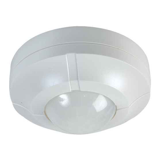
- Page 1 360° Surface Mount PIR Light Controller Model: SLW360N...
-
Page 2: General Information
1. General Information These instructions should be read carefully in full before installation and retained for further reference and maintenance. 2. Safety • Before installation or maintenance, ensure the mains supply to the PIR sensor is switched off and the circuit supply fuses are removed or the circuit breaker turned off. -
Page 3: Selecting A Location
• Dimensions (H x W x D): 100.5 x 100.5 x 42.5mm • Multiple PIR Sensor Switching: A maximum of 8 SLW360N PIR sensors can be wired in parallel, to enable any detector to turn ON all the lights connected. The total load must not exceed the lamp rating of a single SLW360N unit. -
Page 4: Installation
Diagram A Diagram B Up to 4m Presence Detection Up to 8m Motion Detection 5. Installation • Ensure the mains supply is switched off and the circuit supply fuses are removed or the circuit breaker turned off. • An isolating switch should be installed to enable the power to be switched ON &... - Page 5 • Mark the position of the mounting holes on the ceiling using the sensor as a template. • Drill out the mounting holes taking care to avoid any joists, electrical cables or water/gas pipes that may be hidden beneath the surface. Insert the rawl plugs into the holes. •...
-
Page 6: Connection Diagram
6. Connection Diagram • Connect the cables as follows; 230V 50Hz Mains Supply Live Supply (Brown or Red) to Neutral Supply (Blue or Black) to A ‘Loop Terminal’ is provided should a 3 core cable be used which is marked Switched Load (Light Source) Out Switch Live (Brown or Red) to Neutral Load (Blue or Black) to... - Page 7 7. Setting Up Walk Test (Test Mode) • The adjustment knobs located beneath the sensor head are factory set to “Test Mode” . Double check they are set as follows; Time Setting – fully anticlockwise Lux-Dusk/Dawn Setting – fully clockwise •...
- Page 8 8. Setting Up for Automatic Operation (Auto Mode) • When the walk tests are complete, the unit can be adjusted for automatic operation. • The Time Setting controls how long the unit remains illuminated following activation and after all motion ceases. •...
-
Page 9: Troubleshooting
10. Troubleshooting Problem Solution • The Lamp stays ON Cover the PIR lens with a thick cloth. all the time at night. If the light turns OFF, check the detection area for heat or a reflective source. If the light stays ON, check the wiring (See section 5. - Page 10 • PIR coverage is The PIR may be poorly located. See section 4. poor/sporadic Selecting a location and relocate the unit. • The detection range The PIR detectors are influenced by climatic varies from day conditions. The colder the ambient temperature, to day.
-
Page 11: Year Guarantee
020 8450 0515. Note: A proof of purchase is required in all cases. For all eligible replacements (where agreed by Timeguard) the customer is responsible for all shipping/ postage charges outside of the UK. All shipping costs are to be paid in... - Page 12 If you experience problems, do not immediately return the unit to the store. Telephone the Timeguard Customer Helpline; HELPLINE 020 8450 0515 or email helpline @ timeguard.com Qualified Customer Support Coordinators will be online to assist in resolving your query.
Need help?
Do you have a question about the SLW360N and is the answer not in the manual?
Questions and answers