Table of Contents
Advertisement
Quick Links
Advertisement
Table of Contents

Subscribe to Our Youtube Channel
Related Manuals for Timeguard MLSA360N


Summary of Contents for Timeguard MLSA360N
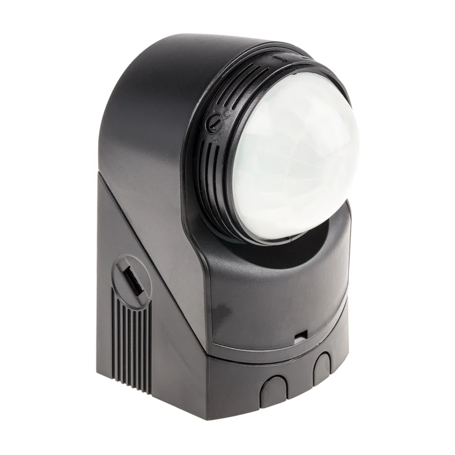
- Page 1 360° Night Eye PIR Light Controller Model: MLSA360N...
-
Page 2: General Information
1. General Information These instructions should be read carefully and retained for further reference and maintenance. 2. Safety • Before installation or maintenance, ensure the mains supply to the PIR sensor is switched off and the circuit supply fuses are removed or the circuit breaker turned off. -
Page 3: Selecting A Location
4. Selecting a Location • The motion detector has number of detection zones, at various vertical and horizontal angles as shown (See diagram “A”) • The optimum mounting height is 2.5m (the minimum is 1.7m) • Careful positioning of the sensor will be required to ensure optimum performance (See diagram “A”... -
Page 4: Installation
Diagram B Diagram C 5. Installation • Ensure the mains supply is switched off and the circuit supply fuses are removed or the circuit breaker turned off. • An isolating switch should be installed to enable the power to be switched ON &... - Page 5 • Pass the 230V 50Hz mains supply and load cables through the cable entry points on the backing pate, ensuring the grommet(s) is used to maintain the IP rating of the PIR sensor. • Fix the mounting plate to the wall using the correct screws for the rawl plugs installed.
- Page 6 Ceiling/Eave Mounting • Please use the following steps for ceiling/eave mounting.
- Page 7 External Corner Mounting • Please use the following steps for external corner mounting. • Please use the following steps to remove the PIR from the corner mounted bracket.
-
Page 8: Connection Diagram
7. Connection Diagram • Connect the cables to the terminal block as follows; ISOLATION SWITCH MAINS SUPPLY LOAD LOOP TERMINAL Mains Supply Load Live (Brown or Red) to L Switch Live (Brown or Red) to L1 Neutral (Blue or Black) to N Neutral (Blue or Black) to N A ‘Loop Terminal’... - Page 9 8. Operation and Testing Adjustment • The PIR can be adjusted using a flathead screwdriver; Walk Test Procedure • The sensor will rotate from left to right, and tilt forward or backward.
- Page 10 • The small arrow on the underside of the sensor indicates the direction of the main detection area. • The adjustment knobs located on the sides of the sensor head factory set to “Walk Test Mode” i.e. LUX set to the ‘Sun’ symbol and the Time set to the minimum.
- Page 11 Setting Up for Automatic Operation When walk tests are complete, the unit can be switched to automatic operation. • The TIME setting controls how long the unit remains illuminated following activation & after all motion ceases. The minimum time (fully anti-clockwise) is approx. 5 seconds, whilst the maximum time (fully clockwise) is approx.
-
Page 12: Manual Override Operation
9. Manual Override Operation Permanent OFF • Flick the isolation switch to the OFF position. Pulse Manual Override Mode– For the light to turn ON • Flick the isolation switch at day or night, OFF/ON twice within 2.5 seconds. The PIR will then be set to activate your lamp the same night. •... -
Page 13: Troubleshooting
10. Holiday Mode Operation • Flick the isolation switch at day or night, OFF/ON within 3.5 seconds to activate the Holiday mode. The PIR will then be set to operate your lamp each night. • The unit will now illuminate continuously until dawn, or until the unit is switched back into auto mode. - Page 14 Check LED status:- If a single LED is constantly visible, the unit is in Manual Override Mode and will illuminate until dawn or until reset to Automatic Mode. To reset to Automatic Mode, switch the internal switch/circuit breaker off/on within one second. Automatic Mode is indicated by scrolling LEDs from Left to right.
-
Page 15: Year Guarantee
020 8450 0515. Note: A proof of purchase is required in all cases. For all eligible replacements (where agreed by Timeguard) the customer is responsible for all shipping/ postage charges outside of the UK. All shipping costs are to be paid in... - Page 16 If you experience problems, do not immediately return the unit to the store. Telephone the Timeguard Customer Helpline; HELPLINE 020 8450 0515 or email helpline @ timeguard.com Qualified Customer Support Co-ordinators will be on-line to assist in resolving your query.
Need help?
Do you have a question about the MLSA360N and is the answer not in the manual?
Questions and answers