Advertisement
Advertisement
Table of Contents

Subscribe to Our Youtube Channel
Related Manuals for Timeguard SLW360L


Summary of Contents for Timeguard SLW360L
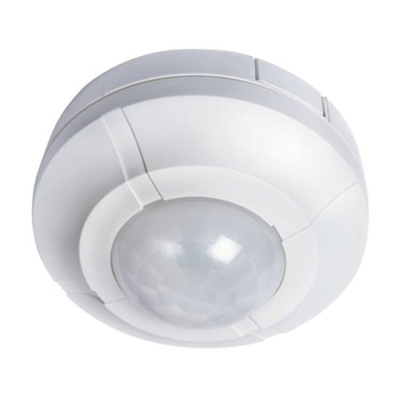
- Page 1 360° Surface Mount Ceiling PIR Light Controller Model: SLW360L...
-
Page 2: General Information
1. General Information These instructions should be read carefully and retained for further reference and maintenance. 2. Safety • Before installation or maintenance, ensure the mains supply to the PIR sensor is switched off and the circuit supply fuses are removed or the circuit breaker turned off. •... -
Page 3: Selecting A Location
4. Selecting a Location • The motion detector has number of detection zones, at various vertical and horizontal angles as shown (See diagram “A”). • The best all-round coverage is achieved with the unit mounted at the optimum height of 2.5 metres. •... -
Page 4: Installation And Connection
5. Installation & Connection • Ensure the mains supply is switched off and the circuit supply fuses are removed or the circuit breaker turned off. • An isolating switch should be installed to enable the power to be switched ON & OFF for maintenance purposes and to activate the manual/auto override function. - Page 5 Switching DC loads or loads which use a different phase or voltage supply from the AC mains – Voltage free Installation (see diagram “H”) Remove the factory fitted ‘bridge’ wire. Connect the 3 core mains supply cable to the terminal block on the unit block as follows:- NEUTRAL (Blue) EARTH (Green/Yellow)
- Page 6 Diagram E Diagram F Diagram G Diagram H In the above illustration: In the above illustration: • 4 core cable may be used • The L1 L2 terminals are used to control a DC load or if the load • There is no external junction box uses a different phase or voltage •...
- Page 7 6. Setting Up • The adjustment knobs located beneath the sensor head (see diagram “F”) are factory set to “Walk Test Mode” . Double check they are set as follows; TIME – Fully anti-clockwise. DUSK – Fully clockwise. • Turn the power to the unit ON. The lamp will immediately illuminate as the unit goes through its “warm-up”...
-
Page 8: Manual Override Mode
• The DUSK control determines the level of darkness required for the unit to start operating. The setting is best achieved by the procedure below; 1. Set the DUSK control knob fully anti clockwise. 2. When the ambient light level reaches the level of darkness at which you wish the lamp to become operative (i.e. -
Page 9: Troubleshooting
10. Troubleshooting Problem Solution Cover the PIR lens with a thick cloth. If the light • Lamp stays ON all the time turns OFF, check the detection area for heat or a night and day. reflective source. If the light stays ON, check the wiring (See section 5. - Page 10 • PIR activates during Adjust the DUSK control setting anti-clockwise the daytime. to lower the level of ambient light required for activation. The PIR may be poorly located • PIR coverage is poor/sporadic (See section 4. Selecting a location) and re-locate the unit. •...
-
Page 11: Year Guarantee
020 8450 0515. Note: A proof of purchase is required in all cases. For all eligible replacements (where agreed by Timeguard) the customer is responsible for all shipping/ postage charges outside of the UK. All shipping costs are to be paid in... - Page 12 If you experience problems, do not immediately return the unit to the store. Telephone the Timeguard Customer Helpline; HELPLINE 020 8450 0515 or email helpline @ timeguard.com Qualified Customer Support Co-ordinators will be on-line to assist in resolving your query.
Need help?
Do you have a question about the SLW360L and is the answer not in the manual?
Questions and answers
is the slw360l still available if not what is its replacement