
Related Manuals for Timeguard PDFMMINIL


Summary of Contents for Timeguard PDFMMINIL
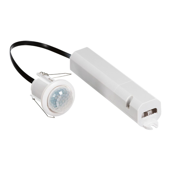
- Page 1 360° Flush Mount Ceiling PIR Light Controller Model: PDFMMINIL Mini Recessed PIR Master Linkable and Power Box Model: PDFMMINILS Mini Recessed PIR Slave Linkable...
-
Page 2: General Information
1. General Information These instructions should be read carefully and retained for further reference and maintenance. 2. Safety • Before installation or maintenance, ensure the mains supply to the PIR sensor is switched off and the circuit supply fuses are removed or the circuit breaker turned off. - Page 3 Multiple PIR Sensor Switching – A maximum of 5 PDFMMINILS Slave PIR sensors can be linked to the PDFMMINIL Master PIR, to enable any detector to turn ON all the lights connected (The total load must not exceed the lamp...
-
Page 4: Installation Advice
4. Installation Advice As the PIR sensor responds to changes in temperature, avoid the following situations: • Mounting the sensor near objects with highly reflective surfaces, such as mirrors etc. • Mounting the sensor near heat sources, such as heating vents, air conditioning units, lights etc. - Page 5 Ø = 40mm 5.2 An isolating switch should be installed to enable the power to be switched ON and OFF for maintenance purposes and to activate the manual override function. 5.3 Mark the position of the 40mm diameter locating hole centre, taking care to avoid ceiling joists and other obstructions within the 40mm diameter.
- Page 6 Note: A maximum of 5 PDFMMINILS Slave PIR sensors can be linked to the PDFMMINIL Master PIR sensor, to enable any detector to turn ON all the lights connected (The total load must not exceed the lamp rating of a single PDFMMINIL unit).
-
Page 7: Connection Diagram
6 Connection Diagram • Connect the 230V 50Hz mains supply cables to the terminal block in the power box as follows; ISOLATION PDFMMINIL Power Box SWITCH LAMP Loop Terminal 230V 50Hz MAINS SUPPLY 230V 50Hz Mains Supply Live Supply (Brown or Red) to Neutral Supply (Blue or Black) to A ‘Loop Terminal’... - Page 8 7. Setting Up Walk Test Procedure • The adjustable LUX and TIME setting controls are factory set to ‘Walk Test’ mode i.e. LUX set fully clockwise to full daylight (Sun symbol) and the TIME set fully anti-clockwise to ‘T’ (Test mode) •...
- Page 9 Ø = 40mm Note: there are no setting controls on the PDFMMINILS slave PIR sensor, only on the PDFMMINIL master PIR sensor. • The TIME setting controls how long the unit remains illuminated following activation and after all motion ceases.
- Page 10 • At this position the unit should become operative at approximately the same level of darkness each evening. • Observe the operation of the unit. If the unit is starting to operate too early (i.e. when it is quite light) adjust the control slightly anti-clockwise. If the unit starts to operate too late (i.e.
-
Page 11: Manual Override Mode
Note: A proof of purchase is required in all cases. For all eligible replacements (where agreed by Timeguard) the customer is responsible for all shipping/postage charges outside of the UK. All shipping costs are to be paid in advance before... - Page 12 If you experience problems, do not immediately return the unit to the store. Telephone the Timeguard Customer Helpline; HELPLINE 020 8450 0515 or email helpline @ timeguard.com Qualified Customer Support Co-ordinators will be on-line to assist in resolving your query.
Need help?
Do you have a question about the PDFMMINIL and is the answer not in the manual?
Questions and answers