Table of Contents
Advertisement
Quick Links
Advertisement
Table of Contents

Subscribe to Our Youtube Channel
Summary of Contents for C-COM Satellite Systems iNetVu 7710
- Page 1 ® iNetVu 7710 Controller User Manual (Includes 7720 RDM) ® The iNetVu brand and logo are registered trademarks of C-COM Satellite Systems, Inc. © Copyright 2018 C-COM Satellite Systems, Inc. 1-877-iNetVu6 www.c-comsat.com May 2, 2018 Revision 8.00 Released with SW Version 7.7.8...
- Page 2 C-COM Satellite Systems Inc. This page is intentionally left blank. iNetVu™ 7710 Controller User Manual...
- Page 3 C-COM Satellite Systems Inc. Copyright © 2018. All rights reserved. C-COM Satellite Systems Inc. This document contains information, which is protected by copyright. All rights reserved. Reproduction, adaptation, or translation without prior written permission is prohibited, except as followed under the copyright laws.
- Page 4 C-COM Satellite Systems Inc. FCC and INDUSTRY CANADA INFORMATION TO THE USER: The FCC and Industry Canada have imposed the following conditions when operating, installing ® and deploying iNetVu Mobile Earth Stations and is mandatory for all installations made within the Continental United States and Canada as well as Hawaii, Alaska, Puerto Rico, the U.S.
- Page 5 C-COM Satellite Systems Inc. 7. Further, the installer and end user may be directly liable for any damages resulting from any change undertaken by either of them. Including but not limited to, any modification of any part of the hardware, software, specific operational frequencies, the authorized satellite, or the size or other characteristics of the earth station supplied to them by C- COM or C-COM’s authorized representatives.
-
Page 6: Table Of Contents
C-COM Satellite Systems Inc. Table of Contents Contents Introduction ........................9 Specifications ........................10 Minimum Recommended PC Requirements ..............10 Physical ..........................11 Typical Connection Configuration ..................12 5.1. Typical Network Interface Connection .................13 5.2. Typical USB Communication Interface ................14 Network Interface Connection – Ku Band Service ............15 5.3. - Page 7 C-COM Satellite Systems Inc. 7.10.9. PW ........................54 7.10.10. SG ........................54 7.10.11. IP ........................54 7.10.12. SR ........................55 7.11. TEST ..........................57 7.11.1. E&A&P ......................58 7.11.2. DPLY ........................59 7.11.3. DPLY_C ......................59 7.11.4. A_ACP ......................60 7.11.5. M_ACP ......................60 7.11.6. S_ACP ......................60 7.12. INFO ...........................61 7.12.1.
- Page 8 Proprietary Notice: This document contains information that is proprietary and confidential to C-COM Satellite Systems, Inc., and is intended for internal and or C-COM Satellite Systems Inc. authorized partners use only. No part of this document may be copied or reproduced in any way, without prior written permission of C-COM Satellite Systems, Inc.
-
Page 9: Introduction
C-COM Satellite Systems Inc. 1. Introduction ® The iNetVu 7710 Controller is a one-box, one-touch solution for satellite auto-acquisition. ® Designed to interface with several Satellite Modems, iNetVu VSATs, and DVB-S/DVB-S2ACM ® ® Receivers, the iNetVu 7710 Controller connects to iNetVu platforms which are equipped with 7720 on-board module (Remote Controller). -
Page 10: Specifications
C-COM Satellite Systems Inc. 2. Specifications Width: 17.1” x Depth: 11.0” Height: 1.75” Dimensions: Weight: 9.9 lbs. (4.5 kg) Operating Temperature: -20°C to +50°C Power Consumption (Idle): 24 VDC @ 1A DC Input: 24 VDC Power Supply (AC/DC): 300W w/o Cooling 350W with 23.5 CFM Cooling Fan... -
Page 11: Physical
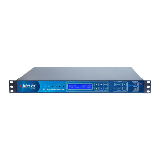
C-COM Satellite Systems Inc. 4. Physical Front View Automatic Front Panel Control LEDs Buttons Manual Control LCD Screen Buttons Reset Keypad Navigator Button GROUND 24 VDC COOLING POWER INPUT RX OUT PROTECT Power Input FANS 100-240 VAC Network Additional Receive... -
Page 12: Typical Connection Configuration
C-COM Satellite Systems Inc. 5. Typical Connection Configuration The typical connection configuration for each service will be the same regardless of the Satellite Modem / VSAT. However, the configuration parameters for Satellite Modem / VSAT ® Communication will differ depending on service. See iNetVu System Manual for configuration procedures corresponding to the service used. -
Page 13: Typical Network Interface Connection
C-COM Satellite Systems Inc. 5.1. Typical Network Interface Connection GPS/Glonass Antenna iNetVu™ Fly-75V Platform COMBINED MOTOR *GROUND & DATA CONTROL PROTECTION CABLE External grounding connection 24 VDC Power Input (If external power source used and or required) 100 - 240VAC Combined Motor &... -
Page 14: Typical Usb Communication Interface
C-COM Satellite Systems Inc. 5.2. Typical USB Communication Interface GPS/Glonass iNetVu™ Fly-75V Antenna Platform *Ground protection COMBINED MOTOR & DATA CONTROL External CABLE grounding connection Network 24 VDC Power Cable Input (If external power source used and or 100 - 240VAC... -
Page 15: Network Interface Connection - Ku Band Service
C-COM Satellite Systems Inc. Network Interface Connection – Ku Band Service 5.3. iNetVu® Fly-981 Control Cable RG6 Coaxial Cable USB Cable Power Cable Network Cable GPS /Glonass iNetVu® 7720 Antenna Controller *Ground protection SAT OUT External CONTROL (Saturated grounding CABLE... -
Page 16: System Diagram With Splitter
C-COM Satellite Systems Inc. 5.4. System Diagram with Splitter **Please Note: Using a splitter is optional. If the user does not wish to power the LNB from the Controller, a splitter must be used such that power is passed to the LNB from the VSAT Modem (or alternate power source). -
Page 17: Typical Connection - Pc Free
C-COM Satellite Systems Inc. Typical Connection – PC Free 5.5. Combined Motor & Data Control Cable iNetVu™ 1201/1202 RG6 Coaxial Cable Mobile Platform GPS/Glonass Network Cable Antenna Power Cable *Ground * Ground Connection protection External grounding connection COMBINED MOTOR & DATA CONTROL... -
Page 18: Installation
C-COM Satellite Systems Inc. 6. Installation ® ® The iNetVu 7710 Controllers are shipped pre-configured and calibrated with the iNetVu Mobile Platform (equipped with the 7720 Remote Drive Module) and service which you plan to use. Only configuration of the Satellite Modem / VSAT Communication parameters and the satellite you wish to find is required. - Page 19 C-COM Satellite Systems Inc. 2. Install the FTDI USB Driver and continue through the Installation Wizard. Click “Extract” Click “Next” Click “Finish” ® 3. Install the iNetVu 7710 Software by accepting defaults and close when complete. iNetVu™ 7710 Controller User Manual...
-
Page 20: Setup
C-COM Satellite Systems Inc. 4. Connect the Controller using the provided USB cable. Windows Vista and 7+ users, the drivers should install automatically without any further user action. ® 5. You have successfully installed the 7710 iNetVu Drivers and Software. Exit the setup wizard. -
Page 21: Inetvu ® 7710 Front Panel Operation
C-COM Satellite Systems Inc. ® 7. iNetVu 7710 Front Panel Operation 7.1. LED DEFINITIONS ® Fig. 9: iNetVu 7710 Series Controller Front Panel LED Panel POWER - Solid light indicates power is ON. REMOTE - 7720 remote controller status. REMOTE LED will flash (Blue) every 1000ms if CANBUS and MODEM communication successful. -
Page 22: Manual And Automatic Controls Button Operation
C-COM Satellite Systems Inc. 7.2. Manual and Automatic Controls Button Operation Fig. 10: iNetVu ® 7710 Series Controller Front Panel Buttons How to Find Satellite Press “FIND SAT” Button. ® iNetVu Mobile Platform will automatically attempt to locate, lock, peak and enable the system to start transmitting on the configured satellite beam or last satellite beam that locked on satellite signal. -
Page 23: Lcd Screen And Navigator Keypad Operation
C-COM Satellite Systems Inc. How to Reset the Controller Press “RESET” Button ® Power-cycles the iNetVu Controller DOES NOT reset default values 7.3. LCD Screen and Navigator Keypad Operation Fig. 11: iNetVu ® 7710 Controller LCD and Keypad Navigator ←... -
Page 24: Front Panel Menu Navigation Tree
C-COM Satellite Systems Inc. 7.4. Front Panel Menu Navigation Tree The following is a tree consisting of a list of the menu options available with the LCD interface. ® iNetVu 7710 Controller LCD Menu MONITOR OPERATION BEAM CONF TEST INFO ➢... -
Page 25: Supported Platforms
C-COM Satellite Systems Inc. MONITOR This menu branch allows the user to monitor the status of the iNetVu Fly-Away/Mobile Platform Axial Movement of EL, AZ, & PL, Target and Reference Satellites, displays information concerning the iNetVu 7710 Controller IP and the Satellite Modem / VSAT and Beacon status. - Page 26 C-COM Satellite Systems Inc. ® A0986A-5 (Fly-98V) --- iNetVu Fly-Away 98cm, 2 Axis (Ka - Viasat ETRIA Transceiver) ® A0986B-1 (Fly-98H) --- iNetVu Fly-Away 98cm, 3 Axis (Ka - HNS Spaceway Transceiver) ® A0986B-2 (Fly-98G) --- iNetVu Fly-Away 98cm, 3 Axis (Ka - Skyware Global Transceiver) Fly-981, 3 Axis New Gen Fly-Away 98cm (Ku –...
- Page 27 C-COM Satellite Systems Inc. LCD Method 1. Advance to the CONF menu using the ‘←’ and ‘→’ arrows on the keypad. 2. Advance to “MT” using the ‘←’ and ‘→’ arrows and press the “Enter” key on the keypad. Select, Platform Type, Platform Version and enter Serial Number where the platform description appears (i.e.
-
Page 28: Monitor
(Modem and Beacon Receiver) Displays Modem status as well as the Beacon Receiver frequency and signal (if a beacon receiver is used) Displays IP of iNetVu 7710 Ethernet Port, and the VSAT modem. (Gateway) Displays Subnet, and Gateway IP. iNetVu™ 7710 Controller User Manual... -
Page 29: Main
C-COM Satellite Systems Inc. 7.7.1. MAIN This branch menu displays the real-time Elevation, Azimuth, Polarization Angles, their respective limits (Up, Down, Stow), the RF Receive Signal, Signal Strength, and the System Status. E-90.0 U D S A -45.7 S VV II P-34.6 S... - Page 30 C-COM Satellite Systems Inc. 5 – System Status (status meanings explained in the software section of this report) ACP Testing ACP Adjustment on Elevation (During Manual ACP) ACP Adjustment on Azimuth ACP Adjustment on Polarization Compass Calibration, Reading, Checking and Restoring...
- Page 31 C-COM Satellite Systems Inc. 7.7.2. Displays real-time current drawn and speed settings for the elevation motor, as well as real-time elevation angle and limits, offset, window size, and Elevation adjustment gap (internally set and not displayed, however can be found in Log file).
- Page 32 C-COM Satellite Systems Inc. 4 - Elevation Offset The number of degrees at which the iNetVu ® Mobile Software will offset the reading from the Inclinometer to produce an accurate (+/- 2°) Elevation Angle (e.g. O: 31 implies elevation offset of 31).
- Page 33 C-COM Satellite Systems Inc. 7.7.4. Displays real-time current drawn and speed settings for the polarization motor, as well as real- time polarization angle and limits, offset, and PL zero. P0.0 S I/S:0.0-7 L R O:0.0 “PL” (Polarization) Display Fig. 20: 1 –...
- Page 34 C-COM Satellite Systems Inc. 2 – GPS Coordinates Current Latitude Coordinate rounded to one decimal place in degree format. Current Longitude Coordinate rounded to one decimal place in degree format. 7.7.6. Displays Search Modes Status, Compass Status, Compass Heading and AZ Window.
- Page 35 C-COM Satellite Systems Inc. 4 - AZ Search Window Status The Search Window is the area of the sky which the iNetVu ® Mobile System will search for the desired Satellite. It uses a rectangular window and searches for the Satellite using smaller concentric windows until the desired Satellite is found.
- Page 36 C-COM Satellite Systems Inc. 7.7.8. This menu displays the Reference Satellite Status, Longitude, Target Antenna Coordinates, DVB Transponder (Frequency, Symbol Rate, and Code Rate) and LNB Power. The reference satellite is another search option that could be utilized by the user. If this option is disabled, only the beam reference satellite will be displayed.
-
Page 37: Hughes Modem Status (Only)
C-COM Satellite Systems Inc. 7.7.9. This menu displays the modem status, beacon frequency and signal strength. SQ : 15 BR :1448.05 0/0dB Fig. 25: Modem and Beacon Receiver 1 – Modem Communication Status, if the controller is still initializing communication with the... - Page 38 C-COM Satellite Systems Inc. 3 – Displays the status of the (RX) Satellite receiver receive state 4 – ACP status enables or disables the ACP routine after locking on signal D - Disables the ACP after locking on signal E - Enables the ACP after locking on signal in which an isolation value is displayed after successfully passing the 2 tests.
-
Page 39: Operation
C-COM Satellite Systems Inc. 7.8. OPERATION LCD Menu options for available searchable satellite beams, enable transmitter, stow, controller restore to default settings and compass calibration routines and functions. Pressing on any option in the operation menu will trigger that command to be performed. - Page 40 C-COM Satellite Systems Inc. 2 – Stow Moves the system to a position where the AZ is zeroed triggering the AZ limit switch and then moving on the EL axis in the up or down direction depending on the configured system. The EL UP or EL ST Limit switches are turned on when movement on EL axis completes.
-
Page 41: Beam
C-COM Satellite Systems Inc. 7 – Restore Compass Factory Calibration (CPR) Restores the compass to factory calibration. Ensure the compass is levelled/flat when restoring to factory calibration for optimum results. 8 – Stop Stops the current operation. 7.9. BEAM The LCD Configuration Interface is password protected. -
Page 42: Sat (Beam)
C-COM Satellite Systems Inc. 7.9.1. SAT (BEAM) 009.0E - 0 MBM059 Y IN:D REF:D BM01_072W Fig. 31: Beam and orbital Configuration 1 – Target Satellite Beam ID 2 – Target longitude and Hemisphere 3 – Transponder number Horizontal Receive (0-2), Vertical Receive (3-5) 4 –... -
Page 43: Dvb
C-COM Satellite Systems Inc. 8 – Reference Satellite Beam ID The reference satellite is another search option that could be utilized by the user. The controller will lock onto the Reference satellite DVB carrier, and will pivot to the target satellite position to peak on the modem signal. -
Page 44: Sr_Cp
C-COM Satellite Systems Inc. 8 – LNB LO Configurable to allow satellite accusation when frequency changes, values range from 10.75, 9.75, 10.00, 10.60 and 11.30. The default value should be set to 10.75, the user is not required to change this value unless necessary, otherwise select the carrier from the table or enter one if not listed. - Page 45 C-COM Satellite Systems Inc. 3 – Compass Heading Compass Heading after Compass has been read. Approximate Headings: North 354 East 87 South 176 West 4 - AZ Search Window The Search Window is the area of the sky which the iNetVu ®...
-
Page 46: Conf
C-COM Satellite Systems Inc. 7.10. CONF ® This Menu will allow the user to select and set the configuration of the iNetVu System as well as the Reference satellite option. The target and the reference satellite(s) can be selected and set from the pre-configured list. -
Page 47: Sat (Conf)
C-COM Satellite Systems Inc. 7.10.1. SAT (CONF) This menu allows for the configuration of the target satellite(s) and the reference satellite. MSS:D BM01_072.0W Fig. 36: Target Satellites display 1 – Multiple Satellite Search This feature when enabled will allow the search to be carried out on three listed target satellites. The search will automatically switch to the next listed target if the previous target search fails. - Page 48 C-COM Satellite Systems Inc. 1 – Modem Parameter Source Configured Satellite Modem to read the Beam ID from the Controller, Modem or Beam ID Table. (HNS Ku Only and iDirect). C – Read Modem Frequency, Symbol Rate etc… from the controller configuration.
- Page 49 C-COM Satellite Systems Inc. 1 – Elevation Offset The Elevation Offset is specific to each type of platform. The user may set the offset with the range of 0º-120º, although altering this number from its default value may give an inaccurate offset reading.
- Page 50 C-COM Satellite Systems Inc. 7.10.6. Allows for the Configuration of the GPS parameters and settings. G :O 45.41N 75.62W Fig. 38: GPS Configuration 1 – GPS Status Configuration Use Coordinates from GPS Antenna Override GPS and use the coordinates entered (2) and (3). Enables the GPS coordinates to be manually overridden.
- Page 51 C-COM Satellite Systems Inc. 1- Platform Type The user can configure the platform type using iNetVu LCD panel. See section 7.6 for complete list of supported platforms. ® A0755A - iNetVu Ka-75V ver.10.x, New Gen Drive-Away 75cm (Ka - Band Circular) ®...
- Page 52 C-COM Satellite Systems Inc. Baud Rate the Modem operates on, prior to configuring the Service, and Communication Interface. MDM--4800 MDM--9600 MDM--38400 b) B_R (Beacon Receiver) The Beacon Receiver is a satellite acquisition lock controller that could be used alongside the 7710 Controller as an option. The Beacon Receiver will lock on the Beacon Frequency of a satellite based on the power density of the signal.
- Page 53 C-COM Satellite Systems Inc. 3 – QPT (Es/No Value) The Maximum energy to noise of a modem or SNR signal that can be configured to save time during the satellite peaking routine. The peaking will transition from standard to quick once the configured Es/No value is reached.
- Page 54 C-COM Satellite Systems Inc. 7.10.9. PWD :: password Fig. 41: Controller and Web GUI Password 1- Current LCD and Web Interface Password The user may change this password by using the “↓” and “↑” buttons on the front panel of the 7710 controller and the “→”...
- Page 55 C-COM Satellite Systems Inc. 1 – iNetVu 7710 Controller’s IP Address ® 2 – Modem IP Address 7.10.12. This menu will allow the user to configure the controller to the service used (select modem type) for 2-way satellite communication. HNS_KU – TYPICAL - HT--0 YE(Y)NN Fig.
- Page 56 C-COM Satellite Systems Inc. NA – Sub-ID Choose Typical for normal operation or select one of the custom created files from the list when using multiple beacon satellite search. User must depress Restore Defaults button to use the selected option and allow features of that selection to propagate to the beam configuration section.
-
Page 57: Test
C-COM Satellite Systems Inc. 7 – Auto Start (iDirect Only) This feature is available with the iDirect service and will automatically start the satellite search as soon as the communication between the modem and controller are established. The Auto Start will not run if the platform is stowed (EL ST & EL DN Limits are ON and EL angle not greater than 10 degrees). -
Page 58: E&A&P
C-COM Satellite Systems Inc. 7.11.1. E&A&P E +20:70:7 P-60: 60:7 A-180: 180:7 DD: D Fig. 46: Test/Demo EL, AZ, PL Configuration 1 – Elevation Range Allows the user to set the start and stop angle of the elevation axis, as well as set the specific speed for elevation movement. -
Page 59: Dply
C-COM Satellite Systems Inc. 5 – Test Selection Initiates the test on the specified axes according to the specified ranges, and speeds. Press up or down key, first letter will flash then press ENTER, the test routine will start. 7.11.2. -
Page 60: A_Acp
C-COM Satellite Systems Inc. 1 – Elevation Movement User-defined target elevation angle offset for compass reading 2 – Polarization Movement User-defined target polarization angle for compass reading 3 – Azimuth Movement User-defined target azimuth angle for compass reading 4 – Check Compass (at specified target point) Tests the compass’... -
Page 61: Info
C-COM Satellite Systems Inc. 7.12. INFO 7710 Controller’s firmware, software versions and ® Displays information regarding the iNetVu MAC address information, the Mobile Platform type currently configured, and any Error Codes detected. DVB_D DVB_P “INFO” (Information) Display Fig. 49: ®... -
Page 62: Cc2
C-COM Satellite Systems Inc. 1 – Controller ID Number The iNetVu ® Controller Serial Number is located on the base of the controller. The ID displays the last 5 digits of the Serial Number. 2 – Signal Quality Threshold ®... -
Page 63: Dvb_D
C-COM Satellite Systems Inc. 7.12.3. DVB_D This branch menu displays the controller DVB Module Type and ID. DVB-S2 (EA) – 0X3C “DVB” (DVB Module) Display Fig. 52: 1 – The DVB Module (Tuner) and ID currently embedded into the iNetVu ®... -
Page 64: Sys
C-COM Satellite Systems Inc. 7.12.5. This menu displays platform type, hardware version, serial number and data recording file size. A0986A--01.X SN13435 R:16024 “SYS” (Platform) information Display Fig. 54: 1 – Indicates platform type and platform hardware version number. 2 – Data recording information (C-COM internal use). -
Page 65: Inetvu 7710 Software Application
C-COM Satellite Systems Inc. ® 8. iNetVu 7710 Software Application ® ® The iNetVu Mobile Software plays an integral role in connecting the operator/user and iNetVu Mobile System. It could communicate with the Satellite Modem, automatically find and lock onto a satellite (Beam) and stow the antenna when completed. -
Page 66: Application Navigating Menus
C-COM Satellite Systems Inc. The Wizard will check Firmware and Software versions if “Yes” is selected to validate the versions are the same and prompt the user to update the Firmware if they are different. Both the 7710 Controller and the 7720 Remote Drive Module will be validated. -
Page 67: Inetvu Application Controls
C-COM Satellite Systems Inc. 8.2.1. iNetVu Application Controls The Controls menu allows users to monitor system parameters and manually move the antenna, as well as conduct automatic processes and functions. Improper use of iNetVu Controls menu can render the iNetVu® Mobile System inoperable and may be in violation of FCC regulations. - Page 68 C-COM Satellite Systems Inc. Signal Strength A real-time Signal Quality Factor (SQF). A value obtained from the Satellite Modem when locked onto a signal. Using a red/yellow/green color-coated system, it denotes the strength of the received signal from the current satellite.
- Page 69 C-COM Satellite Systems Inc. Select Satellite/Beam Satellites/Beams that user can select from by simply clicking on the drop-down arrow. Satellites 1 to 64 can be preconfigured and saved to allow user to search for desired satellite. Beam color will be displayed and will not be selectable if “Auto-select Beam color”...
- Page 70 C-COM Satellite Systems Inc. Angle and Limit Switch Indicators Displays real-time angles and Limit Switch status Elevation Angle Elevation UP Limit Indicator Elevation DOWN Limit Indicator Elevation STOW Limit Indicator Azimuth Angle Azimuth STOW (LEFT and RIGHT) Limit Indicator Polarization Angle or DDD Polarization STOW Limit Indicator Fig.
- Page 71 C-COM Satellite Systems Inc. Manual Movement Elevation Up / Elevation Down Azimuth Left/ Azimuth Right Polarization Counter-Clockwise / Polarization Clockwise Using the Duration and Speed parameters, the Manual Movement Buttons allow you to move the antenna in six (6) directions. For the correct point of reference for the directional movements, you must be facing the Mobile Platform’s Reflector.
- Page 72 C-COM Satellite Systems Inc. To Enable ACP, select “AUTO” or “MANUAL” from the ACP drop down list and click on the ‘Enable/Disable ACP’ Button to initiate. To Stop ACP testing, select “STOP” from the ACP drop down list, and click on the Enable/Disable ACP Button to initiate.
- Page 73 C-COM Satellite Systems Inc. DVB Signal (0-255) DVB Signal received from the DVB Tuner. A “U” next to the value indicates an “unlocked” status. An “L” next to the DVB value indicates locked signal. Beacon Signal (0-100) If the optional beacon receiver is used, the Beacon Signal will appear in this area along with the power density received from the satellite.
- Page 74 C-COM Satellite Systems Inc. Target Satellite parameters Target Antenna Elevation Angle Target theoretical Elevation Angle Target Antenna Azimuth Angle (0 to ± 180) Target theoretical Azimuth Angle (0 to 360) Target Antenna Polarization Angle (0 to ± 90) Target theoretical Polarization Angle Fig.
- Page 75 C-COM Satellite Systems Inc. Target Antenna Elevation Angle (Target Ant. EL) The Target Ant. EL angle is a calculated value based on GPS and satellite longitude information taking into consideration antenna mechanical calibrations. Target Elevation (Target EL) The Target Elevation Angle is the theoretically calculated EL look angle value based on the Antenna’s GPS location and Satellite Longitude.
- Page 76 C-COM Satellite Systems Inc. Compass Heading Orientation of the Mobile and Fly-Away Platforms. This value is only read during the Find Satellite and Check Compass processes. Back of reflector faces North and Azimuth Limit Switch Indicator is North - 354...
- Page 77 C-COM Satellite Systems Inc. Message Panel Displays real-time status updates, system messages, and error codes. Fig. 69: Message Panel Status Panel The Status Panel describes system operations that are either imminent, taking place, or the current status of that component. The Status Panel is located at the bottom of the Controls menus, and has a set of six message blocks, respectively.
- Page 78 C-COM Satellite Systems Inc. System Status Displays current system environment • System Idle No operations are currently being performed. • ACP Testing ACP Testing is being performed. • Skew Adjusting Polarization adjustment to adjust the polarization axis for any vehicle inclination. The Azimuth Axis will rotate 90º...
- Page 79 C-COM Satellite Systems Inc. • Motion Monitoring Detects the Motion and triggers the Motion Detection alert when environmental motion is detected. • Manual ACP on AZ Fine Pointing by adjusting the Azimuth angle manually in small increments during the Cross Polarization isolation measurement.
- Page 80 C-COM Satellite Systems Inc. Motor Status Displays the movement of the 3-axis motors: Elevation, Azimuth, and Polarization • EL Moving UP / DN Elevation Motor is moving in the respective direction (UP = Up, DN = Down) • AZ Moving Left / Right Azimuth Motor is moving in the respective direction •...
-
Page 81: Maintenance
C-COM Satellite Systems Inc. 8.2.2. Maintenance The Maintenance menu allows users to configure the communication between the controller and platform type, as well as various system parameters for optimal performance. Separate tabs have been added to set apart the 3 axis as well as GPS and Compass for easier configuration. - Page 82 C-COM Satellite Systems Inc. 8.2.2.1 Platform Parameters Fig. 72: Maintenance Platform Parameters Type The user can configure the platform type in use via the controller front panel or the software application. The firmware/software application will have a different naming schema under platform type in the drop down than the one provided in the marketing/sales datasheets.
- Page 83 C-COM Satellite Systems Inc. ® A1205A-3 --- iNetVu New Gen Drive-Away 1.2m, 2 Axis (Ka - Viasat SurfBeam Transceiver) ® A1205B-2 --- iNetVu New Gen Drive-Away 1.2m, 3 Axis (Ka - Skyware Global Transceiver) ® A1205C-1 --- iNetVu New Gen Drive-Away 1.2m, 3 Axis, GD REFL, (Ku Band) ®...
- Page 84 C-COM Satellite Systems Inc. 8.2.2.2 Offset EL Offset The Elevation Offset is specific to each type of platform. It is the number of degrees at which the ® iNetVu Mobile Software will offset the reading from the Inclinometer to produce an accurate (+/- 2°) Elevation Angle.
- Page 85 C-COM Satellite Systems Inc. 8.2.2.3 PC Application ® This sub-section contains options regarding the relevant IP address connection to the iNetVu 7700 Series Central Controller. This section allows user to enter IP address of the desired controller that they wish to connect to over the network.
- Page 86 C-COM Satellite Systems Inc. 8.2.2.4 Advanced - Target Satellite The Target satellite drop down allows the user to select from list of saved satellites, longitudinal and orbital values the target satellite to search on, the list will currently save and display 64 target satellites.
- Page 87 C-COM Satellite Systems Inc. GPS Latitude ® This field represents the Latitudinal GPS coordinates of the iNetVu system. GPS Longitude ® This field represents the Longitudinal GPS coordinates of the iNetVu system. 8.2.2.6 Operation Mode Unattended Operation This option is used for remote operations where system is left unattended as the name indicates, mainly for unmanned sites.
- Page 88 C-COM Satellite Systems Inc. TX Protection The TX will be disabled as soon as small or big motion is detected due to extreme motion or ® severe shaking. The iNetVu Mobile Platform will automatically stow if signal is lost and 60 seconds of waiting time have expired, or re-peak should the antenna be locked on signal.
- Page 89 C-COM Satellite Systems Inc. Enable CP Calibration This button puts the compass in a state (CP (1) will display in Compass Heading field) that allows data to be collected and used After getting saved. Movement is manual unless system is put in Demo Test mode which is the recommended method.
- Page 90 C-COM Satellite Systems Inc. Check Compass Tests the compass’ heading and accuracy by rotating the antenna at 90 intervals and comparing the compass readings with the actual antenna’s movement to the 4 positions (0, 90, 180, 270). The mount and or Mobile Platform Vehicle must be pointed North (Vehicle front windshield).
- Page 91 C-COM Satellite Systems Inc. Calibrate Compass Automatically calibrates compass, this button will be greyed out for all Flyaway antennas. vi. The mount and or Mobile Platform Vehicle must be pointed North (Vehicle front windshield). The software will Pop-up a dialog window to confirm this orientation prior to proceeding with the calibration.
- Page 92 C-COM Satellite Systems Inc. *Load 7710 Firmware (Main Controller Firmware) ® Loads the iNetVu7710_Box_FW.S19 firmware file into iNetVu Controller from the iNetVu program folder. The update process is displayed on screen and will notify the user when the process is complete. 7710 Controller will reset itself once the firmware updating is complete.
-
Page 93: Maintenance Test (Demo Window)
C-COM Satellite Systems Inc. 8.2.3. Maintenance Test (Demo Window) ® Used for system tests, trouble-shooting, and for demonstrating the iNetVu Mobile System. This feature is accessible from the Maintenance Window Test button. Start Angles Initial values for the test/demo sequence. - Page 94 C-COM Satellite Systems Inc. Test Compass Positions Antenna to the set Elevation angle and updates compass heading by moving to the set End Angle values entered by the user on all three axis. Only end angles are required when testing or validating compass.
-
Page 95: Configuration
C-COM Satellite Systems Inc. 8.2.4. Configuration The Configuration menu allows users to configure the communication medium between the ® Satellite Modem, Controller (ACU) and iNetVu Mobile Software, as well as various System parameters for optimal performance. Users have the ability to configure and save 64 Satellites (1-65) with their orbital slot. - Page 96 C-COM Satellite Systems Inc. 8.2.4.1 Beam Configuration Configuration – Beam Parameters Fig. 76: Beam ID. 64 different satellite Beam ID are configurable on same or different satellites allowing users to configure and save for easy access. Modem Beam ID (iDirect & HNS_KU Only) Modem Beam ID (number) is read directly from the modem that is configured with Dual Beam coverage or Multiple Beam coverage on iDirect Ku service or HNS Ku service.
- Page 97 C-COM Satellite Systems Inc. 8.2.4.2 Satellite and DVB Transponder Settings Longitude Orbital slot / Longitude of the desired Satellite. The Find Satellite command will use this value when attempting to find and lock onto a satellite signal. Carrier Skew The Carrier Skew is any known Skew on the target satellite. The Carrier Skew is used to adjust the difference between the carrier polarity and physical polarity on the mount.
- Page 98 C-COM Satellite Systems Inc. 7710 Controller Power Output Range Option Capabilities: 13, 14, 18, 19 V @ 500mA (max) If the user chooses to power the LNB from the controller, he/she should verify the power/voltage ® range requirements of the LNB in use and configure the iNetVu 7710 Controller according to those power/voltage requirements.
- Page 99 C-COM Satellite Systems Inc. Symbol Rate (sps) Symbol Rate of receive signal. FEC (Code) Rate FEC Rate of receive signal. Transponder Receive polarity, this field will auto populate as a direct result of Transponder No. selected when the Read Transponder button is triggered, (H) for Horizontal and (V) for Vertical.
- Page 100 C-COM Satellite Systems Inc. 8.2.4.3 Modem Parameters Configurable parameters will differ depending on the type of modem service selected under the type field. Most modems are now read automatically, Satellite search field parameters will have the frequency, Sym Rate, RX&TX and DVB settings read and populated automatically from the modem.
- Page 101 C-COM Satellite Systems Inc. Modem Delay The user may increase the delay time when polling for modem signal by adjusting this number. Increasing this number, will increase the time to find and lock on to satellite as it slows down controller activity and allows slower modems to catch up.
- Page 102 C-COM Satellite Systems Inc. Freq (KHz) and Symb (sps) These two fields represent the required Frequency and Symbol Rate of the VSAT modem. This is usually applied to Hughes Net services only. Other services do not require the modem frequency to find satellite.
- Page 103 C-COM Satellite Systems Inc. iDirect Modem Options: iDirect’s Auto Beam Selection provides the mobile user coverage with a single modem without having to reconfigure the modem when moving between different regions that possess different satellite beams to have continuous coverage.
- Page 104 C-COM Satellite Systems Inc. WARNING!!! The system will start automatically searching on satellite once the power and or communication is established between the controller and modem without having to press the FIND SAT button if Auto Start feature is enabled. Make sure to allow the...
- Page 105 C-COM Satellite Systems Inc. Transmit Polarization set in the satellite modem, Hughes Net service only. LNB 22 KHz Tone The 22 KHz tone can be disabled or enabled for supporting modems. DVB Type Required on Hughes Ku (HX Modem) the DVB-S type of the modem to be set to allow the modem to stay online after the TX enable command has been sent from the controller.
- Page 106 C-COM Satellite Systems Inc. HNS_JT Modem Hughes modem that uses the Jupiter Ka transceiver, with this type of service the search parameters are read directly from the modem. The Satellite and DVB settings are not propagated to the Satellite and DVB Transponder section but can be viewed on the Controls interface.
- Page 107 C-COM Satellite Systems Inc. Used for all supported Gilat modems with iNetVu systems. Motion Customized search routine for Capricorn modem type and any Gilat modem that is compatible with the OpenAMIP interface. This mode will wait to acquire GPS, Compass, and Beam parameters from the modem and then enters “Motion Mode”...
- Page 108 C-COM Satellite Systems Inc. Used for standalone systems where only DVB or Beacon is used to lock onto a satellite. Choose service sub id for multiple beacon satellite search under NA service. Set Typical for normal operation or select one of the custom Configurations that have been created.
- Page 109 C-COM Satellite Systems Inc. 8.2.4.4 Search Parameters The iNetVu controller supports DVB-S and DVBS2ACM carriers. The recommended method of satellite search is DVB using DVB-S/S2, followed by DVB reference satellite search with RF search being the last option of choice. If using RF search, a valid RF frequency must be entered and is highly recommended;...
- Page 110 C-COM Satellite Systems Inc. step-through-search moving the AZ axis in small incremental steps, this method increases the search time. Enable Reference Satellite If this checkbox is selected, the Reference Satellite Option becomes active. The reference satellite option is useful when the user cannot find a DVB transponder on the desired target satellite.
- Page 111 C-COM Satellite Systems Inc. Override Compass Checkbox The Compass is pre-calibrated by a professional installer at the time of system installation and or come pre-calibrated from the compass manufacturer. ® A number of factors can contribute to the iNetVu compass to produce an incorrect reading such as being parked in close proximity to a large metallic object.
- Page 112 C-COM Satellite Systems Inc. 8.2.4.7 Controller Parameters ® This sub-section contains data concerning the relevant IP addresses of the iNetVu 7710 Controller. Configuration – Controller Parameters Fig. 80: IP Address ® The IP address assigned to the iNetVu 7710 Controller.
- Page 113 C-COM Satellite Systems Inc. Peaking Threshold This option will allow the user to set a maximum peaking threshold to transition the peaking from standard (Quadratic peaking method) to quick by setting the threshold value between 55 to 205 (55, 85, 115, 145, 175, 205) based on known maximum signal. Quick peaking will kick in once this value is reached, only change this value if you prefer the quick peaking to kick in after a certain set SNR value is reached otherwise leave at default value of 205.
-
Page 114: About
C-COM Satellite Systems Inc. Restore Defaults Resets all platforms to the manufacture’s default values, and resets beam(s), and modem parameters settings to their defaults. Save All Sends and saves ALL parameters to the controller’s memory. 8.3. About Displays information to the user about various sub-system components, as well as contact information for support and feedback. - Page 115 C-COM Satellite Systems Inc. Software • Version ® iNetVu Mobile Software version. • Build ID Date of software release. 7710 Controller • Firmware Controller’s firmware version. ® iNetVu For compatibility purposes, Controllers are pre-configured with the appropriate firmware for the accompanied software version.
- Page 116 C-COM Satellite Systems Inc. Platform • Type Mobile Platform type. • Serial Number(S/N) Mobile Platform serial number. • Version Mobile Platform hardware version. Satellite • Longitude Orbital slot of Satellite that is currently configured and used by the Beam. •...
- Page 117 C-COM Satellite Systems Inc. • Revision Indicates the revision number of the current Controller Hardware version. • Boot Loader Bootloader version loaded in the 7720 Controller. Compass • Type This will show which compass is installed on the platform, the new iNetVu NAV or the CMPS10.
-
Page 118: Setup Wizard
C-COM Satellite Systems Inc. 8.4. Setup Wizard The Setup Wizard has been implemented to aid first time users in configuring their system after the software has been installed. A Pop-up window will show at first launch allowing the user to use the Setup Wizard (select Yes) or to bypass it (select No) and use it later. -
Page 119: Language
C-COM Satellite Systems Inc. 8.5. Language The multilingual feature allows the toggling between Six (6) languages and updates in real-time the selected language. Currently the available languages are English, Chinese (Simplified and Traditional), Spanish, Russian and Swedish with others to come. -
Page 120: Inetvu 7710 Series Controller Web Interface
C-COM Satellite Systems Inc. ® 9. iNetVu 7710 Series Controller Web Interface The New revamped WEB Interface, has been improved both in looks and functionality. The user can monitor real-time system parameters such as Signal Strength, GPS Coordinates, motor currents, as well as allowing the user the capability of manually moving the antenna just to mention a few of the available functions. -
Page 121: Authentication
C-COM Satellite Systems Inc. MISC. • HELP – This menu selection will provide a detailed description or function clarification of the item, field or sub-menu. • ABOUT – Provides information on 7710 Controller, 7720 RDM, Platform, Compass, Modem and Satellite. - Page 122 C-COM Satellite Systems Inc. To change password, click on “CHANGE PASSWORD” Web Interface – Change Password Screen Fig. 84: To reset the password, click on “RESET PASSWORD”, and enter “123456789” for the reset ID. The password will revert to factory default “password”...
- Page 123 C-COM Satellite Systems Inc. These options are available once the user logs in and puts the controller in upload mode by clicking UPDATE FIRMWARE icon on the Maintenance screen (Firmware, SatParam Table etc.. can be uploaded). • LOGIN • CONTROLLER UPDATE •...
-
Page 124: Automatic Controls
C-COM Satellite Systems Inc. 9.1.2. AUTOMATIC CONTROLS ® Similar to the iNetVu 7710 Software Controls Menu, the Web Interface Automatic Controls window allows the user to monitor system operations and perform satellite search as well as stowing the system. Web Interface – Automatic Controls Screen Fig. -
Page 125: Manual Controls
C-COM Satellite Systems Inc. 9.1.3. MANUAL CONTROLS The Manual Controls allows the user to move the system on the three axes, deploy the system to a set angle, and enable or disable TX. Web Interface – Manual Controls Screen Fig. 88:... -
Page 126: Compass Controls
C-COM Satellite Systems Inc. 9.1.4. COMPASS CONTROLS Web Interface – Compass Controls Screen Fig. 89: iNetVu™ 7710 Controller User Manual... -
Page 127: Maintenance
C-COM Satellite Systems Inc. 9.1.5. MAINTENANCE This section has RESET which restarts the 7710 controller, UPDATE FIRMWARE which allow the firmware to be updated after the controller is in updating mode and finally the RESTORE SETTINGS which will reset all platform related parameters to factory defaults, as well the Beam and Service configuration settings will be reset. -
Page 128: Platform Testing
C-COM Satellite Systems Inc. 9.1.6. PLATFORM TESTING This menu option is mainly used for Demos and testing movements within a specified movement range of the system. Elevation, Azimuth and Polarization movement ranges and speeds can be set as desired. Web Interface – Platform Testing & Demo Screen Fig. -
Page 129: Controller Configuration
C-COM Satellite Systems Inc. 9.1.7. CONTROLLER CONFIGURATION This menu option permits the user to enable Multiple Satellite search, override GPS coordinates, configure controller IP address and com serial interface mode. Operation modes such as Transmit Protection and Peaking Threshold can be enabled by unlocking the fields from the UNLOCK ADVANCED button at the top of the page. -
Page 130: Configuration Buttons
C-COM Satellite Systems Inc. 9.1.8. CONFIGURATION BUTTONS At the top of every Configuration page menu in the Configure section you will find this toolbar. Reboots/Restarts Saves the Hides all configurable the Controller changes fields on the page Unhides all configurable... -
Page 131: Beam
C-COM Satellite Systems Inc. 9.1.9. BEAM The Configuration menu allows users to set the Beam ID, Satellite parameters, orbital slot, and override parameters. Locked, click on the UNLOCK button to configure Web Interface – Beam Configuration Screen Fig. 93: iNetVu™ 7710 Controller User Manual... -
Page 132: Modem
C-COM Satellite Systems Inc. 9.1.10. MODEM Satellite Modem service type selection, and modem parameter configuration that include and are not limited to disable/enable options for ACP, TX_DIS, TX, RX, BC and 22k. Service sub id for multiple beacon satellite search under NA, choose Typical for normal operation or select one of the custom Configurations that have been created. -
Page 133: Platform
C-COM Satellite Systems Inc. 9.1.11. PLATFORM The platform type, version and serial number can be configured here. EL, Compass and PL offset can be set under this menu option. Fig. 95: Web Interface - Platform Configuration Screen iNetVu™ 7710 Controller User Manual... -
Page 134: Help
C-COM Satellite Systems Inc. 9.1.12. HELP Provides information and descriptions about the functions that exist for the iNetVu system. Fig. 96: Web Interface - Help Screen iNetVu™ 7710 Controller User Manual... -
Page 135: About
C-COM Satellite Systems Inc. 9.1.13. ABOUT The “iNetVu About” web page, displays information to the user about various sub-system components for the 7710 Controller,7720 Remote Drive and Modem just to mention a few. Fig. 97: Web Interface - About Screen... -
Page 136: Appendix
C-COM Satellite Systems Inc. Appendix 10.1. Appendix 1: Default Limits and Configuration Data Tables Elevation Offset PLATFORM TYPES Fly-75V Fly-98G/H/V Fly-981 Fly-1202V Fly-1202 (A0756A) (A0986A/B) (A0986C) (A1206A) (A1206C) EL OFFSET 23.5 21.5 PLATFORM TYPES Fly-1801 Ka-75V Ka-98G/H/V Ka-98H 1201A/1205C (A1806C/D/E) -
Page 137: Appendix 2: Compass Direction And System Ref. Az Table
C-COM Satellite Systems Inc. 10.2. Appendix 2: Compass Direction and System Ref. AZ Table System Ref. Direction Search Window Starting Angle North (N) = 0 North West (NW) = 45 East (E) = 90 -135 South East (SE) = 135... -
Page 138: Appendix 3: Updating Firmware On 7710&7720 Controllers
Power ON the PC and the 7710 Controller which will also provide power to 7720 (it is assumed that the Power & Data cable is connected to 7720 remote drive module). Open the iNetVu 7710 Controller Software Connect the PC to the Controller through a USB interface. -
Page 139: Appendix 4: System Configuration Using Setup Wizard
C-COM Satellite Systems Inc. 10.4. Appendix 4: System Configuration Using Setup Wizard The Setup Wizard will launch every time the iNetVuMobile7700 software is executed, select “Do not show this message again” to allow software to go straight to the Controls Window when the software application is launched. - Page 140 C-COM Satellite Systems Inc. 4. The Setup Wizard will check and ensure Firmware and Software versions are the same, if not the same version you will be prompted to update, select Yes. 5. Put controller in firmware update mode by following instructions on the screen.
- Page 141 C-COM Satellite Systems Inc. Firmware update status will be displayed on bottom of screen. The wizard will resume after 7710 Firmware update completes. The wizard will prompt you to update the 7720 firmware after the 7710 firmware update finishes. Click OK and put the controller in firmware update mode.
- Page 142 C-COM Satellite Systems Inc. 9. Click “Update Firmware for 7720” button. Controller will reset after firmware update completes and the wizard will automatically flip to the next screen. iNetVu™ 7710 Controller User Manual...
- Page 143 C-COM Satellite Systems Inc. 10. Select and or enter Platform type, version and Serial number and click Next. iNetVu™ 7710 Controller User Manual...
- Page 144 C-COM Satellite Systems Inc. 11. Select the service type (Modem service used), and interface, along with Controller and Modem information. Hover over each field to get tips, examples and clear explanation. Click Next. iNetVu™ 7710 Controller User Manual...
- Page 145 C-COM Satellite Systems Inc. 12. Satellite information screen, allows user to configure Satellite, Search Method and DVB settings. Enter and select Parameters/Settings for the Satellite used with your platform. Click Finish. 13. Click Yes to save and exit. 14. Launch the Application by double clicking the iNetVuMobile7710 icon.
-
Page 146: Appendix 5: Dc Input Power Cable Connectivity
C-COM Satellite Systems Inc. 10.5. Appendix 5: DC Input Power Cable Connectivity Controller Receptacle External Cable Plug J1 Panel Receptacle P1 Straight Plug 4-Socket Contacts Mating View 4-Pin Contact Mating View P1 External Cable Plug Pin List (4-CONTACTS) RECEPTACLE SIGNAL Notes Must have an Inline Fast Blow Fuse –... - Page 147 C-COM Satellite Systems Inc. Materials Required for External Cable: Part # Quantity Description 206429-1 TEConnectivity AMP CPC Plug Assembly, Shell Size 11, Reverse Sex, 4-Pin Contacts, Series 1 206358-5 TEConnectivity AMP CPC Cable Clamp, Size 11 66361-4 TEConnectivity AMP CPC Pin Contact, Series 1, Wire 18-...
-
Page 148: Appendix 6: Supported Modems
C-COM Satellite Systems Inc. 10.6. Appendix 6: Supported Modems Service Type Modem Type Hughes HN7000/7700/7740/7740S HX90/100/200/260 HN_KA Hughes HN 9200 (Ka) HN 9400 (Ka) HN 9600 (Ka) HN 9800 (Ka) HT (Jupiter) Hughes HT 1100/1200/1300 HT 2000 iDirect iDirect X5... -
Page 149: Appendix 7: 7710 Error/Message Code Definition
C-COM Satellite Systems Inc. 10.7. Appendix 7: 7710 Error/Message Code Definition Error Code Description Comments 0X6330 Peaking Succ(INC) 0X7100 Detect AZ Stow Switch 0X7101 Detect AZ Stow Switch and RESET AZ Zero Point 0X7102 Detect AZ Left Limit 0X7103 Detect AZ Left Limit and RESET AZ Angle... - Page 150 C-COM Satellite Systems Inc. 0X8102 AUTO ACP failed after MANUAL ACP 0X8103 ACP fatal error 0X8105 The first MANUAL ACP failed Motion Detection/Tooway Look-up Table 0X8200 Failed to disable TX Motion protection 0X8300 Look-up table for Tooway not available 0X8301 Can’t find beam in look-up table for Tooway...
- Page 151 C-COM Satellite Systems Inc. 0X9018 AZ Protection ON EL Limit 0X9019 AZ END LIMIT1(Left) Protection 0X901A AZ END LIMIT2(Right) Protection 0X9020 PL Protection ON EL Limit 0X9021 PL END LIMIT1(CCW) Protection 0X9022 PL END LIMIT2(CW) Protection 0X9030 EL Position Failed(20S)
- Page 152 C-COM Satellite Systems Inc. 0XF000 CANBUS communication (PL) Failed System Peaking 0X4011 Quadratic peaking step 1 0X4012 Quadratic peaking step 2 0X4013 Quadratic peaking step 3 0X4014 Quadratic peaking step 4 0X4015 Quadratic peaking step 5 0X4016 Quadratic peaking step 6...
- Page 153 C-COM Satellite Systems Inc. 10.8. Appendix 8: Declaration of Conformity iNetVu™ 7710 Controller User Manual...
Need help?
Do you have a question about the iNetVu 7710 and is the answer not in the manual?
Questions and answers