
Subscribe to Our Youtube Channel
Related Manuals for ZIEHL-ABEGG ZA dynpro


Summary of Contents for ZIEHL-ABEGG ZA dynpro
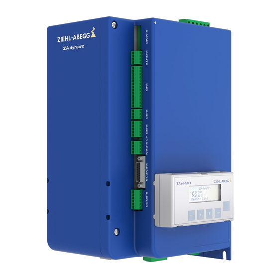
- Page 1 dynpro Frequency inverter Original operating instructions Store for future use! Part 1 -Installation -Start-up R-TBA17_01-GB 1837 Index 004 Part.-No. 00163459-GB...
-
Page 2: Table Of Contents
Original operating instructions ZAdynpro – Part 1 Content General ..............Validity . - Page 3 Original operating instructions ZAdynpro – Part 1 5.15 Rotary encoder simulation (X-ENCO) ........5.16 External 24 V voltage supply (X-ENCO) .
-
Page 4: General
(compare chapter 5.2 "EMC compatible installation") only with the expert use of a line reactor. ZIEHL-ABEGG recommends the use of the line reactor of type NDxx which is optimally geared to the ZAdynpro (compare also chapter 5.5. “Mains connection”). Also outside the area of application of standards EN 12015 and EN 12016, the use of a line reactor is the precondition for the validity of the type examination of the STO function (Safe Torque Off according to DIN EN 61800-5-2). -
Page 5: Copyright
ZIEHL-ABEGG SE. Infringements are liable for damages. All rights reserved, including those that arise through patent issue or registration on a utility model. -
Page 6: Product Safety
Parts and special equipment not supplied by the ZIEHL-ABEGG SE are not approved for use. The warranty shall be void if the device is tampered with or modified without authorisation. -
Page 7: Operator's Obligation Of Diligence
Original operating instructions Safety instructions ZAdynpro – Part 1 Operator’s obligation of diligence The device has been designed and constructed with consideration of a hazard analysis and after carefully selecting the harmonized standards to be complied with as well as additional technical specifications. -
Page 8: Product Overview
Product overview ZAdynpro – Part 1 3 Product overview System overview The drive system for ZIEHL-ABEGG SE elevators consists of several individual components. 1) ZAdynpro Frequency inverter for RPM control of asynchronous motors and synchronous motors. 2) Power choke System component to reduce current harmonics and to attenuate commutation notches and line feedback. -
Page 9: Name Plate
3.5 mA, or a direct current of 10 mA CE mark Internal DATA MATRIX code of ZIEHL-ABEGG SE Service & maintenance These jobs must be completed during the recurrent maintenance work: Check the device for dirt and clean if necessary •... -
Page 10: Disposal / Recycling
Original operating instructions Mechanical installation ZAdynpro – Part 1 Disposal / recycling Disposal must be carried out professionally and environmentally friendly in accordance with the legal stipulations. 4 Mechanical installation General notes The frequency inverter ZAdynpro is designed for mounting on the wall in the switch cabinet. •... -
Page 11: Dimensional Drawings / Minimum Distances
Original operating instructions Mechanical installation ZAdynpro – Part 1 Dimensional drawings / Minimum distances ZAdynpro 011-017 ZAdynpro 023-032 R-TBA17_01-GB 1837 Index 004 Part.-No. 00163459-GB 11/64... -
Page 12: Electrical Installation
Original operating instructions Electrical installation ZAdynpro – Part 1 5 Electrical installation General Danger! It is forbidden to carry out work on the frequency inverter when it is live. Even after disconnection, the DC-link ( terminals X2: +DC / X2:-DC ) are still live. Wait at least 3 minutes before working on the device Danger! It is not permitted to operate the ZAdynpro with the housing covers removed, as exposed live parts... -
Page 13: Electrical Connection
In order to use the ZAdynpro safely and in compliance with standards, a power choke of type ND... from ZIEHL-ABEGG must be integrated into the power line. For assignment of the frame sizes of the ZAdynpro to the respective power chokes, refer to chapter "Electrical installation/Mains con- nection". -
Page 14: Emc-Compatible Assembly Of The Control Cabinet
Original operating instructions Electrical installation ZAdynpro – Part 1 5.2.3 EMC-compatible assembly of the control cabinet The following points must be observed if the stand- ards outlined in chapter "EMC-compatible installa- tion/Standards" are to be adhered to: Refer to chapter "EMC-compatible installation/Stan- •... -
Page 15: Terminal Positions
Original operating instructions Electrical installation ZAdynpro – Part 1 Terminal positions 5.3.1 ZAdynpro 011-032 Front terminal positions 1 X-MMC memory card 2 X-OUT2 digital outputs 3 X-IN digital inputs 4 X-BC temperature monitoring for brake resistor/brake chopper 5 X-BR inputs for function monitoring of the motor brakes 6 J4 terminating resistance CAN line 7 X-CAN CAN 8 X-ENC15 rotary encoder SUB-D... -
Page 16: Protective Ground Connection
Original operating instructions Electrical installation ZAdynpro – Part 1 Protective ground connection The ZAdynpro has a leakage current of > 3.5 mA according to the defined networks in • DIN EN 60990 and must therefore be permanently connected. • In accordance with EN 50178, item 5.2.11 and 5.3.2.1, the PE conductor connection must have a cross-section of at least 10 mm². -
Page 17: Residual Current Operated Device (Rccb)
If an FI circuit breaker is required for special reasons (e.g. fire prevention), an all-current-sensitive FI circuit breaker type B must be used. For maximum operational reliability, ZIEHL-ABEGG recommends the use of an FI circuit breaker with a reference fault current of 300 mA for fire prevention according to regulation VdS 3501. -
Page 18: Brake Resistor (X 2)
Original operating instructions Electrical installation ZAdynpro – Part 1 Brake resistor (X 2) Designation of the con- nection terminal: Max. 6 mm Line cross-section: Shielded Type of cable: Maximum 5 m • Cable lengths: • If the pre-assembled line is not long enough in the brake resistor of the BR11-A type, this can be extended up to a length of 5 m. -
Page 19: Motor Connection (X 3)
Original operating instructions Electrical installation ZAdynpro – Part 1 Type BR11-A Brake resistor BR11-A possesses connected connecting wires. These must be wound twice around the toroidal core provided. It is important to wind both wires with the same direction of winding (see figure). -
Page 20: Digital Inputs (X-In)
Original operating instructions Electrical installation ZAdynpro – Part 1 Digital inputs (X-IN) X-IN Designation of the con- nection terminal: 8, freely configurable Number of the digital in- puts: The digital inputs comply with the IEC61131-2 TYPE 2 industry standard. Technical data: Voltage range: +22 ... - Page 21 Original operating instructions Electrical installation ZAdynpro – Part 1 Caution! The internal 24 V power supply is provided solely for the digital inputs. Switching consumer load with CAUTION! this voltage is prohibited! Terminal assignment X-IN • You can configure the inputs I1 … I8 assignments. The configuration can be implemented by: –...
-
Page 22: Digital Outputs (X-Out1, X-Out2)
Original operating instructions Electrical installation ZAdynpro – Part 1 Binary travelling speed default Standard (CONFIG=15:ZA_BIN) Binary inputs Travel speed V_3 BIN2 BIN1 BIN0 5.10 Digital outputs (X-OUT1, X-OUT2) X-OUT1 Designation of the con- nection terminals: X-OUT2 X-OUT1: 3, freely configurable Number of outputs: X-OUT2: 2, freely configurable Technical data:... -
Page 23: Can Interface (X-Can)
Original operating instructions Electrical installation ZAdynpro – Part 1 Terminal assignment of X-OUT1, X-OUT2 The output assignments can be configured. The configuration can be implemented by: • – Presetting the used control system (assignment corresponding to the control requirements) – Free configuration Implement configuration of the digital outputs in the Control system\CONFIG menu. -
Page 24: Sto Interface (X-Sto)
Original operating instructions Electrical installation ZAdynpro – Part 1 To activate the terminating resistance, the jumper at terminal J4 must be plugged into the right two pins (see Fig.). Jumper at terminal J4 For more detailed information on CANopen lift, see chapter "Serial communication/CANopen lift" in part 2. - Page 25 Original operating instructions Electrical installation ZAdynpro – Part 1 Danger! If you use an external voltage source instead of the internally generated 24-V voltage (X-STO: +24V_STO) to actuate the STO inputs, you must use a voltage source with low voltage and safe electrical disconnection (SELV/PELV).
-
Page 26: Connection Of Asynchronous Motor Rotary Encoder (X-Enc15)
Original operating instructions Electrical installation ZAdynpro – Part 1 Terminal assignment X-STO Name Function +24V_STO 24VDC output voltage (to be used only for activation of the STO inputs, do not connect any additional loads) Reference potential 24VDC output voltage STO_A Input STO A GND_STO Reference potential, inputs STO_A/B STO_B... -
Page 27: Rotary Encoder Connection For Synchronous Motors (X-Enc15)
Original operating instructions Electrical installation ZAdynpro – Part 1 Housing Shielding 5.14 Rotary encoder connection for synchronous motors (X-ENC15) X-ENC15 Designation of the con- nection terminal: D-Sub, 15-pin, in two rows Connection type: Max. 25 m Cable lengths: Shielded twisted pair cable Type of cable: Type: Rotary encoder, absolute... -
Page 28: Rotary Encoder Simulation (X-Enco)
Original operating instructions Electrical installation ZAdynpro – Part 1 5.15 Rotary encoder simulation (X-ENCO) The rotary encoder simulation transforms the signals of the rotary encoder mounted on the motor • into differential signals according to ANSI standard RS422. The resolution of the rotary encoder simulation is identical to the resolution of the rotary encoder. -
Page 29: Connection X-Ext
Original operating instructions Electrical installation ZAdynpro – Part 1 5.16.2 Connection X-EXT X-ENCO GND_ +24V_ Connection external power supply 1 external power supply () terminal designation of connector 5.17 Standby input (X-SBY) By applying a 24-V voltage, the standby mode of the ZAdynpro is activated. •... -
Page 30: Motor Contactors (Optional)
Original operating instructions Electrical installation ZAdynpro – Part 1 5.18 Motor contactors (optional) The STO connection must be bridged if motor contactors are used (see fig.). X-STO +24V_ STO_A GND_ STO_B STO connection bridged The monitor of the STO function must also be deactivated. The STO function is activated/deactivated in the Monitors/STOmenu. -
Page 31: Monitoring Of The Motor Contactors (X-Br)
Original operating instructions Electrical installation ZAdynpro – Part 1 5.18.1 Monitoring of the motor contactors (X-BR) Danger! Operating lift drives is only permissible with connected and activated contactor monitoring! Information The switching states of the motor contactors must be monitored according to EN 81-20. The ZAdynpro contactor monitoring is no substitute for this monitoring of the motor contactors demanded in EN 81-20! General... -
Page 32: Brakes
Original operating instructions Electrical installation ZAdynpro – Part 1 5.19 Brakes 5.19.1 Brake release monitoring (X-BR) • The brake release monitoring serves as monitoring for redundancy and the operation status of the brakes. • It is recommended that the brake release monitoring be connected to the ZAdynpro for optimum starting and stopping. - Page 33 Original operating instructions Electrical installation ZAdynpro – Part 1 ZAdynpro X-BR +24V_ Brake release monitoring connection with inductive proximity switches 1 Lift drive 0 terminal designation of connector Information The internal 24 V power supply is only provided for the inputs of the ZAdynpro. Switching consumers with this voltage is not permitted! R-TBA17_01-GB 1837 Index 004 Part.-No.
-
Page 34: Zadynpro Circuit Suggestion
Original operating instructions Electrical installation ZAdynpro – Part 1 5.20 ZAdynpro circuit suggestion R-TBA17_01-GB 1837 Index 004 Part.-No. 00163459-GB 34/64... -
Page 35: Operation And Parameterising
Original operating instructions Operation and parameterising ZAdynpro – Part 1 6 Operation and parameterising Options for control To operate and configure the ZAdynpro, the following control options are available: • ZApadpro control terminal • Remote control via ZAmon software • Remote control via the elevator controller display 6.1.1 ZApadpro control terminal... -
Page 36: Menu Navigation
Original operating instructions Operation and parameterising ZAdynpro – Part 1 Menu navigation 6.2.1 ZApadpro and ZAmon control interface ZApadpro and ZAmon control interface 1 Display 2 i key 3 Enter key 4 Arrow UP key 5 Arrow DOWN key 6 ESC key 6.2.2 Control key functions •... -
Page 37: Menu And Parameter Navigation
Original operating instructions Operation and parameterising ZAdynpro – Part 1 6.2.3 Menu and parameter navigation ZIEHL-ABEGG SE - Actuate with any key Main page ZAdynpro SN: 09229587/0002 Phone: +49 794016308 ZAdynpro - Select required menu with the Menu section ->Startup... -
Page 38: Meaning Of The Arrows Appearing In The Display
Original operating instructions Operation and parameterising ZAdynpro – Part 1 6.2.5 Meaning of the arrows appearing in the display: M o t o r- T y p e n s c h i l d E n c o d e r & B C Selecting a menus in the menu level A n l a g e - d a t e n S t e u e r u n g... -
Page 39: Start-Up
Original operating instructions Start-up ZAdynpro – Part 1 7 Start-up General Danger! Defective connections can cause the motor to start unexpectedly or lead to uncontrolled motor movements. Reversed connections cause the motor to rotate in the wrong direction. That can cause serious machine damage. - Page 40 Original operating instructions Start-up ZAdynpro – Part 1 Startup Select parameter U - " - " Enter the motor's rated voltage Nominal voltage Startup Select parameter P - " - " Enter the motor's rated power Nominal Power Start-up Select parameter cos phi cos phi 0.75 - "...
-
Page 41: Testing The "Safe Torque Off Function (Sto)
Original operating instructions Start-up ZAdynpro – Part 1 Start-up Select parameter CONFIG CONFIG 01: ZA_IO - " Configuration of the digital inputs according to the used control 01: ZA_IO - " system and type of communication Configuration Select parameter MO_DR Start-up Changing the rotating direction of the motor MO_DR... -
Page 42: Setting The Switch-Off Points
Original operating instructions Start-up ZAdynpro – Part 1 Test step Result At standstill of the drive (no travel signals), bridge the In the Info menu/Start/Stop, the STO_B input must normally open contact of the relay for triggering the initially be marked as active by a large dot. A large STO_B signal so that the STO_B input is activated. -
Page 43: Optimisation Of The Startup And Drive Behaviour
Original operating instructions Start-up ZAdynpro – Part 1 Optimisation of the startup and drive behaviour Turning away when starting up Turning away when starting up is indicated by uncontrolled movement of the driving disc. The reason for this is insufficient amplification of the RPM controller at the time when the brake opens. RPM controller The SPD_KP (amplification) parameter can be used to optimise the setting of the RPM controller acting during travel. -
Page 44: "Safe Torque Off (Sto)" Function
Original operating instructions "Safe Torque Off (STO)" function ZAdynpro – Part 1 8 "Safe Torque Off (STO)" function General The "Safe torque off (STO) function in the ZAdynpro product series corresponds to the "Safe torque • off (STO)" stop function in accordance with DIN EN 61800-5-2. •... -
Page 45: Principle Circuit Diagram
Original operating instructions "Safe Torque Off (STO)" function ZAdynpro – Part 1 Principle circuit diagram ZAdynpro X-STO +24V_ STO_A GND_ X-OUT STO-Info STO_B 24V I1 (10) O51 O54 Principle circuit diagram "Safe Torque Off (STO)" function 1 Electrical safety chain 2 Modulation 3 Protected routing or design with two separate jacketed cables (see chapter "STO interface (X-STO)") 4 Digital inputs control... -
Page 46: Notes On Use Of Motors
Original operating instructions "Safe Torque Off (STO)" function ZAdynpro – Part 1 X-STO 120 ms 190 ms < T < 1480 ms STO_A STO_B X-OUT STO_Info Faulty activation STO 1 Error "STO: Fault” 2 Error "STO: Diagnostic" The following times must be kept in operation for sufficient test coverage by the diagnostics. Activation STO (switch-off of STO_A and STO_B) at least once an hour for at least 1,600 ms. -
Page 47: Deactivation Of The Sto Function
"Safe Torque Off (STO) Function / Notes on Opera- tion") TÜV Rheinland conducted type examination and certification for this. Copies of the test certificates can be requested from Ziehl-Abegg. assuming maximum device load for the entire life cycle R-TBA17_01-GB 1837 Index 004 Part.-No. -
Page 48: Enclosure
Original operating instructions Enclosure ZAdynpro – Part 1 9 Enclosure Technical data for ZAdynpro ZAdynpro ZAdynpro article number 352250 352251 352252 352253 352254 Electrical data Mains connection voltage 3~ 180 ... 440 absolut Mains frequency [Hz] 50 / 60 (±1,5 Hz) Typ. -
Page 49: Ec/Eu Declaration Of Conformity
ZAdynpro – Part 1 EC/EU declaration of conformity - Translation - (english) A-KON16_06-GB 1741 Index 003 Manufacturer: ZIEHL-ABEGG SE Heinz-Ziehl-Straße 74653 Künzelsau Germany The manufacturer shall bear sole responsibility for issuing this EC/EU declaration of conformity. Product description: Control devices ZAdyn/ZETADYN for elevator machines Frequency inverters with a safe torque off (STO) function according to the Machinery directive 2006/42/EC, Annex IV, Nr. - Page 50 The authorised representative for the assembly of the technical file is: Mr. Roland Hoppenstedt (see above for address). Künzelsau, 10.10.2017 (location, date of issue) ZIEHL-ABEGG SE ZIEHL-ABEGG SE Werner Bundscherer Roland Hoppenstedt Director Drive Division Technical Director Drive Division...
-
Page 51: Adjustment Card
Original operating instructions Enclosure ZAdynpro – Part 1 Adjustment card "Motor name plate" menu Control system menu Start menu MOT_TYP CONFIG M_START MO_DR K_START CTRL f_I01 f_I02 f_I03 f_I04 V_T3 f_I05 BRK_DMP cos phi f_I06 M_Max f_I07 Acceleration menu f_I08 A_POS f_XBR1 R_POS1... -
Page 52: Type Designation
Original operating instructions Enclosure ZAdynpro – Part 1 Type designation ZAdynpro Model range Rated current 11 A 13 A 17 A 23 A 32 A R-TBA17_01-GB 1837 Index 004 Part.-No. 00163459-GB 52/64... -
Page 53: Certificates
Original operating instructions Enclosure ZAdynpro – Part 1 Certificates R-TBA17_01-GB 1837 Index 004 Part.-No. 00163459-GB 53/64... - Page 54 Original operating instructions Enclosure ZAdynpro – Part 1 R-TBA17_01-GB 1837 Index 004 Part.-No. 00163459-GB 54/64...
- Page 55 Original operating instructions Enclosure ZAdynpro – Part 1 R-TBA17_01-GB 1837 Index 004 Part.-No. 00163459-GB 55/64...
- Page 56 Original operating instructions Enclosure ZAdynpro – Part 1 R-TBA17_01-GB 1837 Index 004 Part.-No. 00163459-GB 56/64...
- Page 57 Original operating instructions Enclosure ZAdynpro – Part 1 R-TBA17_01-GB 1837 Index 004 Part.-No. 00163459-GB 57/64...
- Page 58 Original operating instructions Enclosure ZAdynpro – Part 1 R-TBA17_01-GB 1837 Index 004 Part.-No. 00163459-GB 58/64...
- Page 59 Original operating instructions Enclosure ZAdynpro – Part 1 R-TBA17_01-GB 1837 Index 004 Part.-No. 00163459-GB 59/64...
- Page 60 Original operating instructions Enclosure ZAdynpro – Part 1 R-TBA17_01-GB 1837 Index 004 Part.-No. 00163459-GB 60/64...
- Page 61 Original operating instructions Enclosure ZAdynpro – Part 1 R-TBA17_01-GB 1837 Index 004 Part.-No. 00163459-GB 61/64...
- Page 62 Original operating instructions Enclosure ZAdynpro – Part 1 R-TBA17_01-GB 1837 Index 004 Part.-No. 00163459-GB 62/64...
-
Page 63: Index
Original operating instructions ZAdynpro – Part 1 Index Advanced Level Name plate away when starting up is operate and configure Basic Level operating levels Binary travelling speed de- fault Brake release monitoring Pictographs Brake resistor Product safety Brake-Resistor connection Protective ground connection Brakes Residual current operated CAN interface... - Page 64 Customer Service phone +49 7940 16-308 +49 7940 16-249 drives-service@ziehl-abegg.com Headquarters ZIEHL-ABEGG SE Heinz-Ziehl-Strasse · 74653 Künzelsau Germany phone +49 7940 16-0 · fax +49 7940 16-249 drives@ziehl-abegg.de www.ziehl-abegg.com...
Need help?
Do you have a question about the ZA dynpro and is the answer not in the manual?
Questions and answers