
Subscribe to Our Youtube Channel
Related Manuals for ZIEHL-ABEGG ZETADYN 4C


Summary of Contents for ZIEHL-ABEGG ZETADYN 4C
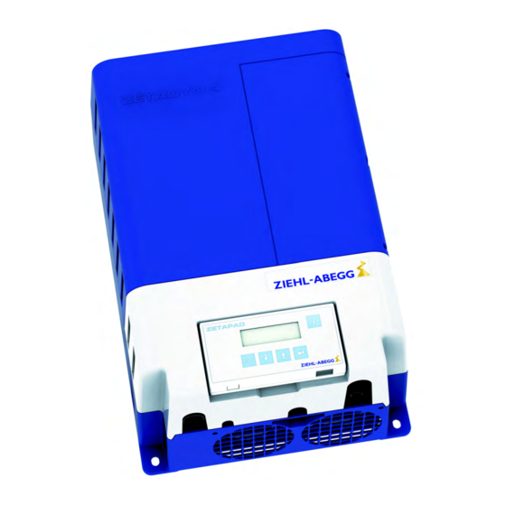
- Page 1 ZETADYN 4C Frequency inverter Translation of the original operating instructions R-TBA12_01-GB 1415 Part.-No. 00163371-GB...
-
Page 2: Table Of Contents
Line laying ZETADYN 4C ........ - Page 3 5.23 Connection suggestion ZETADYN 4C ........
- Page 4 Translation of the original operating instructions ZETADYN 4C 6.1.2 Dimensions ...........
- Page 5 Translation of the original operating instructions ZETADYN 4C 10.2.2.2 Network Management Status ......
- Page 6 Parameterisation ..........13.4 Connection diagram for UPS to ZETADYN 4C .......
- Page 7 17.1 Technical data ZETADYN 4C ........
- Page 8 Translation of the original operating instructions ZETADYN 4C 17.6 Declaration of conformity ..........
-
Page 9: General Information
4.46 Structure of the operating instructions These operating instructions help you to work safely on and with the frequency inverter ZETADYN 4C. They contain safety instructions that must be complied with as well as information that is required for failure-free operation of the frequency inverter. -
Page 10: Copyright
Intended use The ZETADYN 4C is a frequency inverter for RPM control of three-phase current motors. The device is not designed for any other use than those listed here – this is considered as improper use. -
Page 11: Product Safety
All planned modifications must be authorized by the manufacturer in writing. Use only genuine spare parts / genuine wearing parts / genuine accessories from the ZIEHL-ABEGG SE.These parts were specifically designed for the device. There is no guarantee that parts from non- original sources are designed and manufactured in correspondence with load and safety require- ments. -
Page 12: Operator's Obligation Of Diligence
You must monitor their working methods in order to intervene in good time if necessary. 3 Product overview Application The ZETADYN 4C is a field-oriented Frequency inverter for speed control of three-phase motors developed for use in elevator machines. The frequency inverter is equipped with a microprocessor control. This tracks the motor through time and distance-restricted programs that are selected using the superordinate elevator control system. -
Page 13: Current Consumption Of The Zetadyn 4 During Acceleration
4 Mechanical installation General notes The ZETADYN 4C frequency converter is a closed compact device that is designed for wall mounting in the machine room or lift shaft. It can also be installed in the switch cabinet but adequate cooling must be provided in this case (see chapter "Switch cabinet installation"). -
Page 14: Switch Cabinet Installation
Mark the positions of the lower fastening points. " 2 Lower fastening points Drill the fastening holes (the ZETADYN 4C can be moved to the side and must not be removed). " Fix the ZETADYN 4C with one screw each at the lower fastening points. -
Page 15: Dimensions / Minimum Distances
Wait at least 3 minutes before working on the device Danger! It is not permitted to operate the ZETADYN 4C with the housing covers removed, as exposed live parts are present inside the frequency inverter. Failure to observe this provision can lead to serious injury. -
Page 16: Emc-Compatible Installation
Translation of the original operating instructions Electrical installation ZETADYN 4C Work on electric components may only be carried out by trained electricians or by persons instructed in electricity under the supervision of an electrician in accordance with electrical engineering regula- tions. -
Page 17: Cables Motor / Brake Resistor
Translation of the original operating instructions Electrical installation ZETADYN 4C 5.1.1 Cables motor / brake resistor 5.1.1.1 Cable length Motor line: the maximum line length is 25 m. Brake resistor line: the maximum line length is 5 m. In the case of a supply line > 25 m (motor line) or > 5 m (brake resistor line), it is no longer possible to guarantee compliance with DIN EN 12015 (Electromagnetic compatibility –... -
Page 18: Contacting The Shielding On The Motor
Connect the shielding on the motor side to the PE junction that is located directly on the motor housing. For prefabricated motor lines from ZIEHL-ABEGG SE, the shielding connection is provided with a ring cable eye for the corresponding thread size. -
Page 19: Control Cables
Translation of the original operating instructions Electrical installation ZETADYN 4C 5.1.2 Control cables The shields of the control cables (digital inputs and outputs, DCP) must be connected to earth potential on the converter side. Earth clips are available in the ZETADYN 4 for this (see fig.). -
Page 20: Sto Line
Translation of the original operating instructions Electrical installation ZETADYN 4C 5.1.3 STO line For the STO signals, it is possible to use separate jacketed cables or a protected routing. Shielded lines must be used in each case, The shield must be placed on both sides. The shielding of the STO lines must be connected to earth potential over a large area on the inverter side. -
Page 21: Terminal Positions
Translation of the original operating instructions Electrical installation ZETADYN 4C Terminal positions Terminal positions top 1 X-STO Safe Torque Off 2 X-MT motor temperature monitor 3 X-ENC15 rotary encoder SUB-D 4 X-ENC8 rotary encoder 5 X-IN digital inputs 6 X-CAN CAN... -
Page 22: Wiring
Brake resistor cable Clip, second recess from bottom right X-DCP, X-IN, X-ENC8, X-CAN, X-MON, X-ENC8 lines Recess bottom right 5.3.1 Line laying ZETADYN 4C Line laying front 1 Power line, X-OUT line 2 Protective earth connection 3 Brake resistor cable... -
Page 23: Protective Ground Connection
PE conductor on the connecting lead. M6 threaded bolts are available on the ZETADYN 4 for connecting the PE conductors (see fig.). Protective earth conductor connection ZETADYN 4C Mains connection (X1) -
Page 24: Line Reactor-Radio Interference Filter
If an RCD circuit breaker is required for special reasons (e.g. fire protection), an all current-sensitive RCD circuit breaker type B must be used. For maximum operational reliability Ziehl-Abegg recom- mends the use of an RCD circuit breaker with reference fault current 300 mA for fire protection according to regulation VdS 3501. -
Page 25: Control Transformer In The Mains Feed Line
Translation of the original operating instructions Electrical installation ZETADYN 4C Control transformer in the mains feed line Caution! When using a control transformer in the ZETADYN 4’s mains supply line, you must connect a capacitor CAUTION! parallel to the transformer’s primary winding (see Fig.). -
Page 26: Connection
The electronic short-circuit is also active when there is no operating voltage on the ZETADYN 4. • Please contact Ziehl-Abegg if you want to switch off the electronic short-circuit. When operating synchronous motors from other manufacturers, make sure that they can be operated... -
Page 27: Motor Temperature Monitoring (X-Mt)
ZETADYN 4C 5.11 Motor temperature monitoring (X-MT) Information The X-MT terminal is a standard part of the ZETADYN 4C frequency inverter. Information The detection of over temperature of the motor doesn't cause a drive interruption. The current drive will be completed. - Page 28 Toroidal core BR11-A Information The pre-assembled line of the BR11-A does not have double insulation. You can order a retrofit kit for routing in accordance with VDE 0100-400 from ZIEHL-ABEGG SE. Item number: 357260 Cable length The maximum line length is 5 m.
-
Page 29: Digital Inputs (X-In)
Translation of the original operating instructions Electrical installation ZETADYN 4C Brake-Chopper connection ZETADYN 4C ST11 ST12 X-MON ST14 +24V Connection of BC25 / BC50 / BC100 1 Max. contact load: 5 A / 250 VAC 5.13 Digital inputs (X-IN) Standard,8there are digital inputs available on the X-IN 8 terminals for parallel activation of the frequency inverter. -
Page 30: Connection With Internal Power Supply
Translation of the original operating instructions Electrical installation ZETADYN 4C 5.13.2 Connection with internal power supply +24V X-IN +24V (10) (11) (12) (13) Connection of digital input with internal power supply 1 Modulation () terminal designation of connector * Wire number of the pre-assembled connecting lead X-I... -
Page 31: Terminal Assignment X-In
Translation of the original operating instructions Electrical installation ZETADYN 4C 5.13.4 Terminal assignment X-IN You can configure the inputs I1 … I8 assignments. The configuration can be implemented by: • Presetting the used control system (assignment corresponding to the control requirements) •... -
Page 32: Binary Traveling Speed Default
Translation of the original operating instructions Electrical installation ZETADYN 4C 5.13.5 Binary traveling speed default Standard (CONFIG=15:ZA_BIN) Binary inputs Travel speed V_3 BIN2 BIN1 BIN0 5.14 Digital outputs (X-OUT) 5.14.1 Digital outputs X-OUT The connection terminal X-OUT is equipped with 5 digital outputs as zero potential relay contacts with normally open function. -
Page 33: Terminal Assignment X-Out
As an alternative to the conventional wiring, it is possible to actuate the ZETADYN 4 via DCP or CANopen lift (see chapter "Serial communication"). Information The X-DCP and X-CAN terminals are standard parts of the ZETADYN 4C. 5.15.1 • Use a shielded cable for the connection. The shielding must be grounded on the inverter side. -
Page 34: Canopenlift
Translation of the original operating instructions Electrical installation ZETADYN 4C 5.15.2 CANopenLift • A shielded bus-cable is not needed, but the data wires should be twisted. • The installation takes place in line structure. The seperate devices are connected to the bus with short branch lines. -
Page 35: Sto Interface (X-Sto)
• When wiring the STO signals, short-circuits and external shorts must be ruled out on power lines and terminal points because the internal diagnostics of the ZETADYN 4C does not detect any short-circuits on the power lines: – Outside the switch cabinet, the STO line must be permanently laid (fixed) and protected against external damage (e.g. -
Page 36: X-Sto Connection
Translation of the original operating instructions Electrical installation ZETADYN 4C 5.16.3 X-STO connection X-STO X-STO 24V* +24V_ +24V_ STO_A STO_A GND_ GND_ STO_B STO_B Connection with internal 24 V voltage and protected routing Connection with internal 24 V voltage using two separate... -
Page 37: Technical Data X-Enc8 X-Enc15
Translation of the original operating instructions Electrical installation ZETADYN 4C Caution! The pin assignment of the SUB-D socket X-ENC15 is not standardised. When using encoders CAUTION! from other manufacturers, make sure that these have the same contact assignment and an interface with identical specification. -
Page 38: Rotary Encoder Connection To Terminal X-Enc8
Translation of the original operating instructions Electrical installation ZETADYN 4C Analog track A Analog track A inverse Analog track B inverse DGND Ground voltage supply of rotary encoder Housing Shielding 5.17.4 Rotary encoder connection to terminal X-ENC8 TTL incremental encoder (5V), sine encoder... -
Page 39: Technical Data X-Enc15
Translation of the original operating instructions Electrical installation ZETADYN 4C 5.18.1 Technical data X-ENC15 Rotary encoder types Absolute value encoder with EnDat, SSI or Hiperface interface Absolute value encoder type ERN1387 Rotary encoder resolution 512 ... 4096 pulse / revolution 120 Ω... -
Page 40: Connection X-Enco
Translation of the original operating instructions Electrical installation ZETADYN 4C 5.19.2 Connection X-ENCO X-ENCO Connection of rotary encoder simulation 1 Signals depending on the rotating direction of the motor (with view to the power take-off side) () terminal designation of connector 5.20... - Page 41 Translation of the original operating instructions Electrical installation ZETADYN 4C X-STO +24V_ STO_A GND_ STO_B STO connection bridged Select the motor contactors depending on the type of motor and the corresponding motor data. According to DIN EN 81-1, the motor contactor contacts must be self-commutated.
-
Page 42: Monitoring Of The Motor Contactors (X-Co)
Translation of the original operating instructions Electrical installation ZETADYN 4C Information If an emergency evacuation is carried out by opening the brakes, the motor windings must be short-circuited for the evacuation to prevent an uncontrolled acceleration of the elevator. The short-circuit generates a speed-dependent braking torque, sufficient in most cases to limit the... -
Page 43: Brakes
The brake release monitoring serves as monitoring for redundancy and the operation status of the brakes. It is recommended to connect the brake air monitor to the ZETADYN 4C for optimum starting and stopping. The monitoring conforms chapter 9.10 of EN81-1:2010 for brakes as protection for the upside traveling elevator car against overspeed. -
Page 44: Connection X-Br
Translation of the original operating instructions Electrical installation ZETADYN 4C Activation of the parameter ensures that the ZETADYN locks on detection of a faulty brake circuit. The ZETADYN lock can only be released by setting the “Monitors / UNLOCK = On” parameter. -
Page 45: Silent Brake Module
Translation of the original operating instructions Electrical installation ZETADYN 4C Caution! Brakes, which are connected to the direct current side, must be protected against excess voltage from CAUTION! the switching actions by using corresponding varistors! Due to the high operating current, master contactors must be used to switch the brakes! Simplified diagram for brake activation... -
Page 46: Connection Suggestion Zetadyn 4C
Translation of the original operating instructions Electrical installation ZETADYN 4C 5.23 Connection suggestion ZETADYN 4C ZETADYN 4C Bremswiderstand Brake resistor X1 L1 PE X2 X-MON +24V_CO +24V_BC X-PAD Bremslüftüberwachung Brake release monitoring X-ENC8 +24V_BR X-ENC15 L-BL X-EXT +24V_EXT GND_EXT X-AN... -
Page 47: Accessories
Translation of the original operating instructions Accessories ZETADYN 4C 6 Accessories Operating terminal ZETAPAD The ZETAPAD is an operating module independent of the ZETADYN 4. It can be used to operate and configure all ZETADYN 3 and ZETADYN 4 frequency inverters. -
Page 48: Connection
Translation of the original operating instructions Accessories ZETADYN 4C 6.1.3 Connection The connection has to be effected on the RJ45-female plug of the operating terminal and the ZETADYN 4 (X-PAD). Connection cable CAT5 network cable, 8-core both sides RJ-45 plug, 8-pole maximum line length: 50 m line cross-section >= AWG26... -
Page 49: Operation And Parameterising
Translation of the original operating instructions Operation and parameterising ZETADYN 4C 7 Operation and parameterising Possibilities for operation and configuration The following operations can be performed with the aid of the various operating facilities on the ZETADYN 4: • The parameters needed for commissioning can be set •... -
Page 50: Control Key Functions
SM250 - " Motortype 7.2.3 The different operating levels The firmware of the ZETADYN 4C is divided into two operating levels: Basic-Level • Three menus are available here: Startup, Statistics and Memory Card • Starting up takes place exclusively in the "Startup" menu. -
Page 51: Meaning Of The Arrows Appearing In The Display
Translation of the original operating instructions Operation and parameterising ZETADYN 4C 7.2.4 Meaning of the arrows appearing in the display: M o t o r- T y p e n s c h i l d E n c o d e r & B C... -
Page 52: Start-Up
Translation of the original operating instructions Start-up ZETADYN 4C Start-up Danger! Defective connections can cause the motor to start unexpectedly or lead to uncontrolled motor movements. Reversed connections cause the motor to rotate in the wrong direction. That can cause serious machine damage. -
Page 53: Parameterising The Zetadyn
With asynchronous motors it is possible to determine the motor data automatically by means of the Autotune function of the ZETADYN 4C and to save them in the parameter memory. See the "Special functions/Autotune Function" for further information about the Autotune function. - Page 54 Translation of the original operating instructions Start-up ZETADYN 4C Start-up Select parameter "U" - " - " Enter nominal voltage of the motor Rated voltage Start-up Select parameter "P" - " - " Enter nominal power of the motor Rated power Start-up Select parameter "cos phi"...
- Page 55 Translation of the original operating instructions Start-up ZETADYN 4C Start-up __is Select parameter "__is" - " - " Enter the installation's type of suspension Suspension Start-up Select parameter "__i1" __i1 23.00 - " Input of i1 of the gearbox ratio i1:i2 23.00...
-
Page 56: Automatic Operating-Curves Default
Translation of the original operating instructions Start-up ZETADYN 4C Start-up SPD_KP 1.00 Select parameter "SPD_KP" - " 1.00 - " Multiplication factor to modify the calculated basic amplification SPD_C Controller basic gain Automatic operating-curves default Using the automatic operating-curve defaults, the parameters responsible for operating curves and travel speeds are pre-assigned dependent on the "installation nominal velocity "V*". -
Page 57: Setting The Switch-Off Points
In synchronous motors, an encoder offset calibration must be made prior to initial travel (see chapter "Special functions/rotary encoder calibration")! When a Ziehl-Abegg motor is purchased in connection with a frequency inverter, the offset alignment is already taken care of. -
Page 58: Optimisation Of The Startup And Drive Behaviour
Translation of the original operating instructions Start-up ZETADYN 4C If this trip can be carried out without any problems and without any fault messages, a normal trip can be made as the next step. If fault messages appear, an error list is available in the “Diagnose” chapter together with the... -
Page 59: "Safe Torque Off (Sto)" Function
9 "Safe Torque Off (STO)" function General The "Safe torque off (STO)" function in the ZETADYN 4C product series corresponds to the "Safe torque off (STO)" stop function in accordance with DIN EN 61800-5-2. Activation of this function ensures that the ZETADYN 4 cannot supply any energy to the motor which can cause a torque. -
Page 60: Principle Circuit Diagram
Translation of the original operating instructions "Safe Torque Off (STO)" function ZETADYN 4C Danger The connected motor is not separated from the ZETADYN 4 by activation of the STO function. Therefore, you must disconnect the ZETADYN 4 from the supply voltage in order to perform work on the wiring or the motor. -
Page 61: Notes For Operation
Translation of the original operating instructions "Safe Torque Off (STO)" function ZETADYN 4C Notes for operation The two STO inputs must be switched simultaneously by separate relays with every travel (two- channel activation). Removal of one of the two STO_A or STO_B input signals already leads to switching off of the output stage. -
Page 62: Notes On Use Of Motors
Translation of the original operating instructions "Safe Torque Off (STO)" function ZETADYN 4C • If the STO input signals are switched off during travel, the error “STO: Interruption” (error 531) is triggered after 200 ms. During first-time start-up and the recurring tests, the function "Safe torque off (STO)" must be tested (see chapter "Start-up/testing the safety function "Safe torque off (STO)"") -
Page 63: Testing The "Safe Torque Off (Sto)" Safety Function
"Safe Torque Off (STO) Function / Notes on Operation") TUEV Rheinland conducted design pattern examination and certification for this. Copies of the test certificates can be requested from Ziehl-Abegg. assuming maximum device load for the entire life cycle R-TBA12_01-GB 1415 Part.-No. -
Page 64: 10 Serial Communication
Translation of the original operating instructions Serial communication ZETADYN 4C 10 Serial communication 10.1 DCP (Drive Control & Position) The DCP-mode enables serial activation of the ZETADYN 4 through an RS485 interface. Through the bi-directional, serial triggering, the control signals are conducted through a 2- or 3-core connection line. -
Page 65: Configuring In Dcp Mode
Translation of the original operating instructions Serial communication ZETADYN 4C Signal curve DCP_01, DCP_03 Signal curve DCP_02, DCP_04 Command byte Speed default byte Status byte B0 Controller enable RF G0 slow speed (V1) S0 Frequency inverter ready for next B1 travel command (start) -
Page 66: Setting The Dcp-Leveling Behavior
All devices work in 11 bit - mode. • By implication, there can be one ZETADYN 4C connected to one bus-system. • When more than one ZETADYN 4C per bus-system are needed, please call Ziehl-Abegg before installing. 10.2.1.3 Bus-cable •... -
Page 67: Electrical Connection
- " Configuration The INFO menu shows CAN information at the pages 14 - 17 (Assumption: "CONFIG" = "02: ZA_CAN"). 10.2.1.7 Operation modes Information For the ZETADYN 4C are two operation modes by using CAN: R-TBA12_01-GB 1415 Part.-No. 00163371-GB 67/204... -
Page 68: Command- And Statusbits Of The Recorder
Position Mode (Position Mode [pp] Position Mode The used mode can be set in the menu "CAN/MODE" of the ZETADYN 4C Generally the mode is sent from the control system to the ZETADYN 4C shortly before start-up. Therefor you have to set the operation mode in the control system. -
Page 69: Parameter
The CAN-specific displays are in the Info menu on pages 14 - 17 (see chapter "Parameters List"). Information The in the ZETADYN 4C adjusted nominal travel speed V* has to be equal or higher than the speed which is sent to the ZETADYN 4C by the control system. Otherwise no drive takes place. -
Page 70: 11 Parameter List
Enter the operated motor type MOT_TYP ASM:Asynchronous motor SMxxx SM160 SMxxx: Synchronous motor External product SM200 SM160: Ziehl-Abegg synchronous motor type SM160 SM225 SM200: Ziehl-Abegg synchronous motor type SM200 SM250 SM225: Ziehl-Abegg synchronous motor type SM225 SM700 SM250: Ziehl-Abegg synchronous motor type SM250... - Page 71 Translation of the original operating instructions Parameter list ZETADYN 4C Factory set- Parameter Description Value range ting Enter the type of encoder used ENC_TYP EnDat/SSI: Absolute rotary encoder Position information is transmitted either via SSI (synchronous EnDat/SSI serial interface) or EnDat protocol...
- Page 72 11:NL_IO: New Lift standard control 11:NL_IO 12:NL_DCP3: New Lift DCP3 12:NL_DCP3 13:SS_IO: Schneider Steuerungen standard control 13:SS_IO 14:SS_DCP3: Schneider Steuerungen DCP3 14:SS_DCP3 15:ZA_BIN: Ziehl-Abegg standard control with binary speed 15:ZA_BIN presetting 16:WL_IO 01:ZA_IO 16:WL_IO: Weber Lifttechnik standard control 17:WL_DCP1 17:WL_DCP1: Weber Lifttechnik DCP1...
-
Page 73: Advanced-Level
Po Russki User Level USR_LEV Basic Choice about the user level which is active on the ZETAPAD Basic Advanced after starting the ZETADYN 4C. Enter password. PASSWD 0 ... 9999 0 = no password New password PW_NEW 0 ... 9999 A number between 0 and 9999 can be used as a password Displays the password in coded form. -
Page 74: Motor Name Plate Menu
Enter the operated motor type MOT_TYP ASM: Asynchronous motor SMxxx SM160 SMxxx: Synchronous motor External product SM200 SM160: Ziehl-Abegg synchronous motor type SM160 SM225 SM200: Ziehl-Abegg synchronous motor type SM200 SM250 SM225: Ziehl-Abegg synchronous motor type SM225 SM700 SM250: Ziehl-Abegg synchronous motor type SM250... - Page 75 Translation of the original operating instructions Parameter list ZETADYN 4C Enter the used brake resistor or brake chopper BC_TYP BR11: Brake resistor type BR11-A BR11 BR50:Brake resistor type BR50 BR50 BR50+BR25: parallel connection of BR25 and BR50 BR50+BR25 BR50+BR50: parallel connection of 2 pieces BR50...
-
Page 76: Installation Menu
Translation of the original operating instructions Parameter list ZETADYN 4C 11.5 Installation menu Enter of installation specific data Information The installation data must be configured before the first trip! The procedure for calculating the installation nominal speed and to preset the travel data is described in the "Commissioning"... -
Page 77: Control System Menu
11:NL_IO: New Lift standard control 11:NL_IO 12:NL_DCP3: New Lift DCP3 12:NL_DCP3 13:SS_IO: Schneider Steuerungen standard control 13:SS_IO 14:SS_DCP3: Schneider Steuerungen DCP3 14:SS_DCP3 15:ZA_BIN: Ziehl-Abegg standard control with binary speed 15:ZA_BIN presetting 16:WL_IO 01:ZA_IO 16:WL_IO: Weber Lifttechnik standard control 17:WL_DCP1 17:WL_DCP1: Weber Lifttechnik DCP1... - Page 78 Translation of the original operating instructions Parameter list ZETADYN 4C Factory set- Parameter Description Value range ting Configuration of the function of the digital inputs I01 … I08 under f_I01 00:Free 01:RF "CONFIG=free" (For description of the functions, see table).
- Page 79 Translation of the original operating instructions Parameter list ZETADYN 4C Factory set- Parameter Description Value range ting Configuration of the function of the digital outputs O1 … O5 f_O1 Fault under "CONFIG=free" (For description of the functions, see MotContact f_O2...
- Page 80 Translation of the original operating instructions Parameter list ZETADYN 4C Parameter Function Explanation Additional speed 3 Additional speed for inspection and return operation 10:V6 Additional speed 4 Additional speed for inspection and return operation 11:V7 Switchover to 2nd parameter set...
- Page 81 Translation of the original operating instructions Parameter list ZETADYN 4C Parameter Function Explanation With active input there is a deceleration after speed 0, even when travel speeds are activated. Distance-dependent deceleration after 42: LZ standstill The deceleration from travel speed V1 depends on the distance programmed for the parameter S_10.
-
Page 82: Monitoring Menu
Translation of the original operating instructions Parameter list ZETADYN 4C Parameter Function Explanation Contact is closed when the output stage is not blocked by the Status of the STO function STO-Info STO function (output is only information, not safety-related). Contact is closed when the output stage is blocked by the STO... - Page 83 Translation of the original operating instructions Parameter list ZETADYN 4C Factory set- Parameter Description Value range ting Motor brake monitoring Input of number and function of the brake monitoring contacts used OFF:no brake monitoring connected 1*NC: 1x normally closed contact (Contact closed when brake...
-
Page 84: Start Menu
Translation of the original operating instructions Parameter list ZETADYN 4C Factory set- Parameter Description Value range ting Automatic arameter control Parameter values are checked for plausibility when entered. The values are corrected or additional parameters changes if neces- sary (see chapter "Error Diagnosis / Automatic Parameter Check") -
Page 85: Acceleration Menu
Translation of the original operating instructions Parameter list ZETADYN 4C Start-up time sequence 11.9 Acceleration menu Definition of acceleration ramp. Parameter Description Value range Factory setting Positive acceleration A_POS 0.25 ... 2.00 m/s² Lower round off during positive acceleration, a higher value... -
Page 86: Decelerating Menu
Translation of the original operating instructions Parameter list ZETADYN 4C 11.11 Decelerating menu Defines the deceleration ramp and optimizes the positioning behavior. Parameter Description Value range Factory setting Negative acceleration A_NEG 0.25 ... 2.00 m/s² upper round off during negative acceleration, a higher value... -
Page 87: Controller Menu
Translation of the original operating instructions Parameter list ZETADYN 4C Factory set- Parameter Description Value range ting additional current feed at closed brakes T_5a 0.0 … 2.0 s T_5b Wait until the motor is currentless 0.0 … 2.0 s Within time T_5b, the powering of the synchronous motor is... -
Page 88: Parameter Set 2 Menu
Translation of the original operating instructions Parameter list ZETADYN 4C 11.14 Parameter set 2 menu A second parameter set can be stored in the frequency inverter. This can be used for: • Emergency evacuation • Normal travel with changed parameter values •... -
Page 89: Memory Card Menu
Translation of the original operating instructions Parameter list ZETADYN 4C visible in Factory Parameter Description Value range the basic setting level Number of travel aborts due to interruption of the controller ST_SRF Cannot be set enable RF during the travel... -
Page 90: Mmc-Recorder Menue
Translation of the original operating instructions Parameter list ZETADYN 4C visible in Factory Parameter Description Value range the basic setting level Save parameters to memory card (copy parameters in the case SAV_PAR of identical systems): • Parameter (.PA4) in directory /4CX/DEVICE/FORCE Here, there is no serial number allocation. - Page 91 Translation of the original operating instructions Parameter list ZETADYN 4C Factory set- Parameter Description Value range ting Directory number REC_NUM Assigned number under which the directory is saved on the memory card. If "0" is entered, the serial number of the fre- quency inverter is used as the directory name.
-
Page 92: Encoder Adjustment Menu
Translation of the original operating instructions Parameter list ZETADYN 4C 11.18 Encoder adjustment menu Contains parameter values required for aligning the absolute value encoders for synchronous motors. The procedure for entering the encoder alignment data is described in the "Special functions" chapter. -
Page 93: Hw-Ident. Menu
Translation of the original operating instructions Parameter list ZETADYN 4C SB_N=3 SB_M [%] SB_T0 SB_T1 Process capture release 1 Inspection trip "UP" or "DOWN" 11.20 HW-Ident. menu Identification of the individual assemblies in the ZETADYN 4. The identification of the assembly is generally downloaded directly from its EEPROM. -
Page 94: Can Menu
ZETADYN 4: 2 Rotary encoder: 4 Bitrate BD_RATE 10 kBd ... 250 kBd 250 kBd Operating mode of the ZETADYN 4C MODE Position / Velocity Position Maximum waiting time for commands of the control system T_CMD 200 ... 3000 ms 1500 ms 11.24... -
Page 95: Info Menu
Line 2: Serial No - - - - - - - - Display of frequency inverter type and frame size: ZETADYN 4C013-A -A: Type ZETADYN 4C for asynchronous motors SN: 06128238/0001 -S: Type ZETADYN 4C for synchronous motors 4.42-110308xx -X: unknown type... - Page 96 Translation of the original operating instructions Parameter list ZETADYN 4C Page 03: Dist Line 2: Dist. - - - - - - - - - - - sa: current position of car in the shaft sa: 0.00 s21: 0.52m s21: calculated deceleration path V_2 R V_1 sr:^0.00 s31: 1.45m...
- Page 97 Translation of the original operating instructions Parameter list ZETADYN 4C Page 05: MotDatFW Display of the calculated motor data with field weakening operation: MotDatFW- - - - - - - - - I: 11.0A n: 1560rp Line 2: cos:0.89 f: 53.4Hz I0: 3.5A TR: 316ms...
- Page 98 Translation of the original operating instructions Parameter list ZETADYN 4C Page 08: Cu-Functions Online-display Cu Functions- - - - - - Line 2: CONFIG 00: Free Selected control system configuration in menu "Control system/CONFIG" I:RF RV.2 V..Line 3: O:..VG1 Active digital input functions: •...
- Page 99 Translation of the original operating instructions Parameter list ZETADYN 4C Page 11: Encoder Online-display Encoder - - - - - - - - - Line 2: Incr:2048 Type:ENDAT Configured rotary encoder resolution Enable Err: 0 ·· Detected rotary encoder type (with absolute value encoders) Cnt:3941=345°...
- Page 100 Translation of the original operating instructions Parameter list ZETADYN 4C Page 12: Power2 Cause for excess current malfunction Power2 - - - - - - - - - - Line 2: ERR_EXT U. OC: ... ERR_EXT: Excess current message (display is not saved; point is only displayed if excess SRC_APP.
- Page 101 Active in position mode CAN Position------ - Line 2: S_CAN + 0mm S_CAN: Relative target position, sent from the control system to the ZETADYN 4C Contr.:Disab. Volt. Line 3: Status:Sw.On Disab. Contr. Control-byte. Shows commands which are sent by the control system Line 4: Status: Status byte.
- Page 102 Translation of the original operating instructions Parameter list ZETADYN 4C page 16: CAN Error information Information about telegram errors in CANopen lift operation CAN Error Info------ Line 2 (from left to right): Err act. Last:No Err Error status Rec Tra Warn Pas off...
- Page 103 Translation of the original operating instructions Parameter list ZETADYN 4C Page 20: InfoBus Display of frequency inverter configuration InfoBus - - - - - - - - - Line 2: Ident No 01234567 Ident no. of the internal assemblies Exist: xxxx...
-
Page 104: 12 Travel Options
Translation of the original operating instructions Travel options ZETADYN 4C 12 Travel options 12.1 Normal travel The figure shows the sequence of a trip between two floors with the corresponding input and output signal processes. You can find a detailed description of the various acceleration and deceleration processes in this chapter. -
Page 105: Optimizing Start Up Behavior
Translation of the original operating instructions Travel options ZETADYN 4C Start-up and acceleration RF Controller enable V_1 Positioning speed V_3 Travel Speed RV1 / RV2 Direction default RB Controller ready MB_Brake Mechanical brake 12.3 Optimizing start up behavior Optimizing the start up behavior is only necessary if there is a negative influence on the travel comfort (e.g. -
Page 106: Damping The Start-Up Jerk
Translation of the original operating instructions Travel options ZETADYN 4C Time optimisation through contactor monitoring (optional) With monitoring of contactors activated (Monitors/CO activated) and monitor contacts connected the time T_0 is optimised. As soon as the contactors are closed, the time T_0 is interrupted and the time T_1 started. -
Page 107: Optimizing The Acceleration
Translation of the original operating instructions Travel options ZETADYN 4C Start-up variations Controller enable Positioning speed Travel Speed RV1 / RV2 Direction default Controller ready MB_Brake Mechanical brake Flux build-up time Brake opening time Speed=0 K_START MOD1 / MOD2 (Speed control) MOD3 (position- &... -
Page 108: Traveling Speed Defaults
Translation of the original operating instructions Travel options ZETADYN 4C 12.5 Traveling speed defaults After entering the installation specifications and carrying out the automatic parameter assignment, the traveling speeds "V_2" and "V_3" are pre-configured in the Travelling menu, dependent on "V*". -
Page 109: Arch Travel With Path-Dependent Deceleration
Translation of the original operating instructions Travel options ZETADYN 4C The current to the motor is switched off Output RB is switched off Motor contactors must drop immediately 9 10 Normal stop during path dependent deceleration RF Controller enable V_1 Positioning speed... -
Page 110: Time-Dependent Deceleration
Translation of the original operating instructions Travel options ZETADYN 4C 9 10 Arch travel RF Controller enable V_1 Positioning speed V_3 Travel Speed RV1 / RV2 Direction default RB Controller ready MB_Brake Mechanical brake That means that during a normal trip and during arch travel, the deceleration path V3 R V1 (S_31) and the crawl path V1 R speed 0 (S_1, only with DCP 1/DCP 3) are identical. -
Page 111: Deceleration When Traveling Speed Has Not Been Reached
Translation of the original operating instructions Travel options ZETADYN 4C Time-dependent deceleration with reached traveling speed RF Controller enable V_1 Positioning speed V_2 Intermediate speed V_3 Travel Speed RV1 / RV2 Direction default RB Controller ready MB_Brake Mechanical brake 12.7.2 Deceleration when traveling speed has not been reached When the switch off point for the traveling speed is reached, the configured final speed... -
Page 112: Optimizing Deceleration
Translation of the original operating instructions Travel options ZETADYN 4C Information If the trip duration is monitored by the open loop control, due to the long trip time with a traveling speed of V_1 an error message may result! Information If the traveling speed is switched off just before the preset final speed has been reached, it could... -
Page 113: Crawl Path Optimization
Translation of the original operating instructions Travel options ZETADYN 4C Information Adapting the parameter modifies the deceleration path V_3 R V_1. The recalculated path is shown in the display. If necessary, correspondingly adapt the interrupt point for V_3. 12.9 Crawl path optimization Improvement of: •... - Page 114 Translation of the original operating instructions Travel options ZETADYN 4C Deceleration with non-optimized crawl path RF Controller enable V_1 Positioning speed V_3 Travel Speed RV1 / RV2 Direction default RB Controller ready MB_Brake Mechanical brake Deceleration with optimized crawl path...
-
Page 115: Optimizing Stopping
Translation of the original operating instructions Travel options ZETADYN 4C 12.10 Optimizing stopping Stopping time sequence T_5a T_5b X-IN X-OUT T_4 Hold speed 0 T_5 Wait until the brake is closed T_5a additional current feed of the brakes T_5b Wait until the motor is currentless... -
Page 116: Direct Leveling
Translation of the original operating instructions Travel options ZETADYN 4C Information If there are different distances to the flush alignments, it is not possible to travel flush to all floors by modifying the parameter "S_DI1"! Optimizing the step alignment RF Controller enable... -
Page 117: Readjustment
RB Controller ready MB_Brake Mechanical brake 12.14 Operation in idle With the ZETADYN 4C frequency inverter, both synchronous as well as asynchronous motors can be operated in an idle state. Caution! CAUTION! When operating synchronous motors in idle, strong vibrations and noise development can result! Therefore, the factor for the speed controller basic-amplification "SPD_KP"... -
Page 118: Fast-Start
Translation of the original operating instructions Travel options ZETADYN 4C 12.15 Fast-start The motor is energized as the cabin door closes and the mechanical brake is opened. Motor speed is controlled to 0. This makes it possible to start travel immediately the door is closed. -
Page 119: Monitoring Functions For Quickstart
Translation of the original operating instructions Travel options ZETADYN 4C Quickstart with standard actuation RF Controller enable v=0 Hold speed 0 V1 Positioning speed V3 Travel speed V_3 Quick start with DCP actuation RV1 / RV2 Direction default B0 Converter enable... -
Page 120: 13 Emergency Evacuation
Translation of the original operating instructions Emergency evacuation ZETADYN 4C 13 Emergency evacuation 13.1 Evacuation with 1-phase mains supply 230V AC Due to the low power requirements of a synchronous drive, it is possible to carry out an evacuation trip in the motoric and generatoric direction. -
Page 121: Evacuation With Ups
Translation of the original operating instructions Emergency evacuation ZETADYN 4C In case of a voltage drop (power failure), the configured input with 24 VDC is actuated in order to inform the frequency inverter that a switchover must be made to parameter set 2... -
Page 122: Evacuation Through Ups With Optimum Power
Translation of the original operating instructions Emergency evacuation ZETADYN 4C The control system starts the evacuation trip by activating: • Controller enable • Direction preset (in the direction of the pulling load) • Speed default 13.2.1 Evacuation through UPS with optimum power Information - Characteristics of evacuation with optimum UPS power •... -
Page 123: Parameterisation
Translation of the original operating instructions Emergency evacuation ZETADYN 4C 13.2.3 Parameterisation (1) The following prerequisites must be present: The direction of travel of the car is downwards with Standard 24V signal on input configured to Command byte 1, Bit 4 has 1-sig- "RV2"... - Page 124 Translation of the original operating instructions Emergency evacuation ZETADYN 4C Calculating the available UPS power: 1 rating plate - Control systempower consumption - Electromechanical brakes power consumption - Other consumers (car light, …) power consumption = Available UPS_power [W] Information Entering the UPS power determines the type of UPS evacuation.
-
Page 125: Improving The Positioning
Translation of the original operating instructions Emergency evacuation ZETADYN 4C 13.3 Improving the positioning Due to the reduced UPS power, it is not possible to decelerate the motor until standstill. That means, at the time when the floor is reached and the brakes are closed, the motor is still moving. The time delay until the brakes are closed can lead to overshooting the door zone area and thus step formation. -
Page 126: Connection Diagram For Ups To Zetadyn 4C
Translation of the original operating instructions Emergency evacuation ZETADYN 4C 13.4 Connection diagram for UPS to ZETADYN 4C 1 Uninterruptible power supply 2 Phase failure relay 3 elevator control system 4 Output paramterised to "Evac.Dir" function (information direction of generator) 5 Input parameterised for "PARA2"... -
Page 127: Emergency Evacuation By Opening The Brakes
Caution! Short-circuiting the motor windings must be authorized by the motor manufacturer. This is tested and CAUTION! guaranteed in Ziehl-Abegg motors. 13.5.1 Monitor function Monitoring of evacuation direction and evacuation speed during the evacuation process. The monitoring function will be activated by a digital input. -
Page 128: 14 Error Diagnosis
Translation of the original operating instructions Error diagnosis ZETADYN 4C 14 Error diagnosis 14.1 Travel abort and acknowledgement during malfunctions 14.1.1 Travel abort If the ZETADYN 4 detects an error, the actual travel program is aborted and following outputs are switched off immediately: •... -
Page 129: Led
Translation of the original operating instructions Error diagnosis ZETADYN 4C 14.2 A LED is available to diagnose the ZETADYN 4. The LED lights in various colours. 1 LED position Status of the ZETADYN 4 with standard activation LED colour LED status... -
Page 130: Software Update
Translation of the original operating instructions Error diagnosis ZETADYN 4C 14.2.1 Software update If an error occurs during the software update, a flash code is issued by LED for the corresponding error message. An explanation of the flash code can be found in the chapter Special Functions/Software Update 14.3... -
Page 131: Delete Error Memory
Translation of the original operating instructions Error diagnosis ZETADYN 4C Scroll through fault list: the fault list can be scrolled through using the two arrow keys. Scroll up (reduce fault serial number) Scroll down (increase fault serial number) Determine time of fault... -
Page 132: Block Function
Translation of the original operating instructions Error diagnosis ZETADYN 4C 14.5.2 Block function Blocks the controller if certain errors occur several times is succession. The errors must occur in directly consecutive travel tests. The fault counter is set to 0 when performing a trouble-free run. -
Page 133: Error 2Xx
Translation of the original operating instructions Error diagnosis ZETADYN 4C Error no. Error text Error cause The print module ID no. was not detected: ● MP: No ID Module Print is not present or its ID EEPROM does not reply Internal shunt module was detected but there are problems with the shunt ●... -
Page 134: Error 3Xx
Translation of the original operating instructions Error diagnosis ZETADYN 4C Error no. Error text Error cause Error: While operating asynchronous motors, the values for the rated speed ● ● (n) and the rated frequency (f) do not match in the "Motor name plate" menu... - Page 135 Translation of the original operating instructions Error diagnosis ZETADYN 4C Error no. Error text Error cause Error: EnDat encoder delivers error EnDat: HW-error ● Error: Configured resolution in the EnDat encoder does not match the EnDat ● encoder resolution EnDat: Resolution Remedy: Configure the correct EnDat encoder resolution in the "Encoder &...
- Page 136 Translation of the original operating instructions Error diagnosis ZETADYN 4C Error no. Error text Error cause Error: Start-Bit of the EnDat-protocol is not detected Remedy: Check EnDat encoder ENC: Error NDEF Check rotary encoder line Check rotary encoder connection (e.g. shielding)
-
Page 137: Error 4Xx
Translation of the original operating instructions Error diagnosis ZETADYN 4C 14.5.7 Error 4xx • Abort travel to protect the ZETADYN 4 • Voltage monitoring • Overvoltage Brake resistor / Brake-Chopper • Power stage temperature recording • Current monitoring Error no. -
Page 138: Error 5Xx
Translation of the original operating instructions Error diagnosis ZETADYN 4C Error no. Error text Error cause MP: Overcurrent! Error: In one motor phase, overcurrent was measured ● Remedy: Check the motor connection (short-circuit, earth fault), Check rotary encoder connection, Check the "SPD_KP" parameter in the "Control system" menu, MP: Overcurr. - Page 139 Translation of the original operating instructions Error diagnosis ZETADYN 4C Error no. Error text Error cause MB/ENC fault Error: Frequency inverter does not receive a rotary encoder signal at a target ● ● speed >10 cm/s Additional information: Motor current in ampere Remedy: check motor connections (U R U;...
- Page 140 Translation of the original operating instructions Error diagnosis ZETADYN 4C Error no. Error text Error cause Quickstart alarm Error: During a quick start function, the machine moves more than 7 mm while ● ● input "V=0" is triggered Remedy: Check the parameter in the "Motor name plate" menu, Shorten time during which input "V=0"...
- Page 141 Translation of the original operating instructions Error diagnosis ZETADYN 4C Error no. Error text Error cause MOT: Overload ! Error: Motor current exceeds the value max for time Tmax ● ● Remedy: Check the parameter in the "Motor name plate" menu,...
-
Page 142: Error 7Xx
Translation of the original operating instructions Error diagnosis ZETADYN 4C Error no. Error text Error cause RV1/RV2:Change Fault: Change the direction specification during active travel ● ● Additional information: Display of the set direction 1 = RV1 3 = RV2 Remedy: Check control of travel directions 14.5.9... -
Page 143: Error 9Xx
Translation of the original operating instructions Error diagnosis ZETADYN 4C Error no. Error text Error cause CAN: Timeout Enab.- Error: Det. Control system gives command "Enable Operation" not within T_CMD Adjustment: Increase time for T_CMD CAN: Timeout Dis. Op. Error: Control system gives command "Disable Operation"... - Page 144 Only one travel with the actual rope remains. Remedy: Change ropes and reset the down counter. After resetting the ZETADYN 4C there is one additional drive possible. STO: Diagnostic Error:The status of the STO A and STO B signals was different for at least 310 ●...
-
Page 145: Information Texts
Translation of the original operating instructions Error diagnosis ZETADYN 4C 14.5.12 Information texts An information text appears in the display for approx. 2 s for faults which are not saved in the fault list. Information text Cause CO-Interrupt During a non distance-dependent travel (speeds V4 ... V7) the travel contactors are opened. -
Page 146: Frequent Startup Problems
Translation of the original operating instructions Error diagnosis ZETADYN 4C status Condition of the frequency inverter status Condition of the frequency inverter Delay of automatic acknowledgement after reme- Accelerate to speed Vx dying the cause of the fault (2 s) -
Page 147: Automatic Parameter Check (Apc)
Translation of the original operating instructions Error diagnosis ZETADYN 4C 14.8 Automatic parameter check (APC) The Automatic parameter check checks the input values for plausibility and tolerances while the parameters are being entered. The APC function aims to prevent erroneous parameter inputs. Every message must be acknowl- edged by the user with the You can activate or deactivate the APC function in the Monitoring/APC menu. -
Page 148: 15 Energy Saving
To save energy at standstill, the ZETADYN 4C can be switched to standby mode. Internal components of the ZETADYN 4 are switched off in standby mode. This means that the ZETADYN 4 has a much lower power loss at standstill. There are two standby modes in the ZETADYN 4C: Standby 1 and Standby 2... -
Page 149: Power Feedback Unit (Pfu)
3 s after deactivation of the digital STANDBY2 input the ZETADYN 4 is ready for operation again. The ST fault output is activated (see diagram). STANDBY 2 Function stand-by 2 mode ZETADYN 4C 1 STANDBY2 input is activated 2 STANDBY2 input is activated... -
Page 150: Electrical Connection Stand-By Mode
Translation of the original operating instructions Energy saving ZETADYN 4C 1 s after deactivation of the digital output PFU the power feedback unit is ready for operation again (see diagram). T_PFU ST-Revcon Function stand-by mode Revcon 1 End of travel 2 Output with the "PFU"... - Page 151 Translation of the original operating instructions Energy saving ZETADYN 4C Connection and parameterisation temperature monitor brake resistance The temperature monitor is connected to a digital input (X-IN or X-BR). The input must be para- meterised to the PFU_BR function. Control...
-
Page 152: 16 Special Functions
Traveling is prohibited before an absolute encoder offset alignment has been performed! Information In Ziehl-Abegg motors, the absolute encoder is already aligned in the factory to the offset value "0". It is no longer necessary to calibrate the absolute value encoder! -
Page 153: Load-Free Alignment Ssi-Encoder
Translation of the original operating instructions Special functions ZETADYN 4C General conditions required for an encoder alignment without load: • The installation and motor data must be configured • Load-free operation (ropes must be removed from the traction sheave) •... - Page 154 Translation of the original operating instructions Special functions ZETADYN 4C Carrying out the load-free alignment with SSI-encoder MMC Recorder Select menu Encoder adjustment ->Encoder Calibration Safety Brake HW Ident. Encoder Calibration Select parameter "ENC_OFF" ENC_OFF 0.00 - " Enter "ENC_OFF=0"...
- Page 155 Translation of the original operating instructions Special functions ZETADYN 4C Adjust encoder mechani- cally? Adjustment by entering the offset value: Mechanical adjustment of the encoder: The encoder is not moved mechanically, the off- Adjust the encoder as exactly as possible to the set value is retained and is corrected by entering value 0 °...
-
Page 156: Load-Free Alignment Endat-Encoder
Translation of the original operating instructions Special functions ZETADYN 4C 16.2.2 Load-free alignment EnDat-Encoder While the EnDat encoder is being calibrated, the ZETADYN 4 energises the motor with direct current. In the process, the rotor jumps to the centre of the nearest pole. In this rotor position, the offset value is saved to the EnDat encoder and the EnDat encoder is subsequently set to position "0". -
Page 157: Checking The Load-Free Alignment Of The Ssi- & Endat-Encoders
Translation of the original operating instructions Special functions ZETADYN 4C Encoder adjustment was successfully finished [EXIT] 16.2.3 Checking the load-free alignment of the SSI- & EnDat-encoders While the rotary encoder calibration is being checked, the ZETADYN 4 energises each individual pole with direct current. -
Page 158: Rotary Encoder Calibration With Closed Brake
Translation of the original operating instructions Special functions ZETADYN 4C Press inspection! Iu + 13.0A Iv + 6.5A WAIT 0/0A 36C Information is shown in the display during automatic adjustment: ||- - - - - - -80° Line 1: ACT >> prog:+15859... - Page 159 Translation of the original operating instructions Special functions ZETADYN 4C Perform calibration of EnDat or SSI encoders MMC Recorder Select menu Encoder adjustment ->Encoder Calibration Safety Brake HW Ident. Encoder Calibration Select parameter "ENC_OFF" ENC_OFF 0.00 - " Enter "ENC_OFF=0"...
-
Page 160: Alignment Absolute Encoder Type Ern1387
Translation of the original operating instructions Special functions ZETADYN 4C Save new ENC_OFF? Query whether determined encoder offset (ENC_OFF) is to be saved [no] [yes] [yes]: Value is saved [no]: Value is not saved 16.2.5 Alignment absolute encoder type ERN1387 The calibration of absolute value encoders of type ERN1387 corresponds to calibration with brake closed. -
Page 161: Error Messages During Absolute Value Encoder Calibration
Translation of the original operating instructions Special functions ZETADYN 4C 16.2.6 Error messages during absolute value encoder calibration Error no. Error text Error cause Measurement was aborted too soon Drop out of inspect. Phase current too small Iu < 200 mA Phase UVW is missing Iv, Iw <... - Page 162 Translation of the original operating instructions Special functions ZETADYN 4C Safety Brake Start capture release by pressing the inspection run push-button Press inspection! [esc] Function successful! Function faile! 0.0s 4.0A Stop inspection Abort inspection run - - - - - - -> jerk1 in both cases.
-
Page 163: Reset
Operating the motor without rotary encoder calibration can cause uncontrolled motor movements! Attention! - Reset 90 and 99 Any pre-configuration carried out in the Ziehl-Abegg factory is lost when the reset is carried out. CAUTION! The parameters are allocated the factory settings. These do not correspond to the pre-config-... -
Page 164: Memory Card
• Internet (www.ziehl-abegg.com) • Email with software from Ziehl-Abegg • With software from Ziehl-Abegg written on a memory card Caution! Carry out a supervised inspection trip after completing the update! 16.5.1.1 Software update with the ZETAPAD operating terminal Perform a software update Insert the memory card in the X-MMC card slot on the controller unit (see figure bottom right). -
Page 165: Software Update Without The Zetapad Operating Terminal
Translation of the original operating instructions Special functions ZETADYN 4C Statistics Select "Memory Card" menu ->Memory Card Confirming menu selection MMC Recorder Encoder-adjust. Memory Card Select parameter "UPDATE" UPDATE - " Confirming menu selection - " Enter "UPDATE=27" Confirm with the key. -
Page 166: Error Flash Code During A Software Update
Translation of the original operating instructions Special functions ZETADYN 4C 16.5.1.3 Error flash code during a software update If an error occurs during the software update, a flash code is issued by LED for the corresponding error message. See the "Error Diagnostics / Light Emitting Diodes" chapter for the position of the LED. -
Page 167: Saving Parameters
Translation of the original operating instructions Special functions ZETADYN 4C 16.5.2 Saving parameters The parameters of a frequency inverter can be saved to the memory card. Information You can only save the parameters of one frequency inverter to the memory card. It is not possible to save the parameters of multiple frequency inverters. -
Page 168: Saving Parameters Lists, Printer Lists And Error Lists
Translation of the original operating instructions Special functions ZETADYN 4C 16.5.4 Saving parameters lists, printer lists and error lists Parameter lists, printer lists and error lists can be saved on the memory card with allocation of the ZETADYN 4 serial number. -
Page 169: Loading Configurations
Translation of the original operating instructions Special functions ZETADYN 4C Saving configurations Statistics Select "Memory Card" menu ->Memory Card Confirming menu selection MMC Recorder Encoder-adjust. Memory Card Select "SAV_CFG" parameter SAV_CFG 0 - " Confirming menu selection - " Line 3: Enter configuration number ("1" in this example) Confirm with the... -
Page 170: Checking The Motor Phases
If the require motor speed for an asynchronous motor n* is above the rated speed n of the motor, the ZETADYN 4C automatically switches over to operation in the field weakening range. In operation with field weakening the magnetizing current I_0 is reduced over the complete speed range of the motor. -
Page 171: Open Loop Operation (Operation Without Encoder)
Translation of the original operating instructions Special functions ZETADYN 4C 16.8 Open loop operation (operation without encoder) Information Restrictions during open loop operation: • no distance dependent deceleration • no arch-travel • possibly higher heating of the motor • worse positioning accuracy than with Closed-Loop-operation •... -
Page 172: Functions With Open-Loop-Operation
Translation of the original operating instructions Special functions ZETADYN 4C Factory set- Parameter Description Value range ting Maximum slip frequency compensation s_LIM autom. precon- figuration Maximum output voltage for the slip compensation U_S_MX 0 ... 300 V Current controller, sets the minumm current with wihich the... -
Page 173: Slip-Compensation
Translation of the original operating instructions Special functions ZETADYN 4C FADE1 < f < FADE2: If the frequency of the rotating field is between FADE1 and FADE2 the current-control depends on the characteristic curve: the higher the frequency the lower is the current impression. -
Page 174: Tilting Protection
Translation of the original operating instructions Special functions ZETADYN 4C FADE1 < f < FADE2 If the frequency of the rotating field in the stator is between "FADE1" and "FADE2" the slip-compensa- tion depends on the characteristic curve: the higher the frequency the higher the slip-compensation. -
Page 175: Improvements With Open-Loop-Operation
Operation with a 3-phase 230 VAC power supply Der ZETADYN 4 ZETADYN 4C can be operated with a voltage supply 3~ 230 VAC. For this purpose, it is only necessary to adapt various monitoring functions to the lower power supply. -
Page 176: Controlled Emergency Stop In Inclined Elevators
Translation of the original operating instructions Special functions ZETADYN 4C 16.10 Controlled emergency stop in inclined elevators If an emergency stop is implemented in inclined elevators by suddenly closing the brakes, the abrupt stop can lead to injury to passengers. To avoide this, the cabin should also be braked controlled in emergency stop. -
Page 177: Configuring The Travel Direction Change Counter
- " menu "Statistic". *Down counter start value Caution! When replacing the ZETADYN 4C the actual value of the down counter "TD_CNT" must be CAUTION! transferred to the new ZETADYN 4C ! 16.11.3 Configuring a preallocated travel direction change counter The functions of a preallocated travel direction change counter are password-protected. -
Page 178: Output Functions
Resetting the travel direction counter Information At the end of maximum change of direction ZETADYN 4C is locked and the error "E950 TD_CNT: Drive Limit" appears in the display. To move the cabin into the position for a cable change after locking the frequency inverter, the ZETADYN 4C must be switched off and back on. -
Page 179: Self-Monitoring Of The Brakes According To En81-A3
Function test according to EN81-1:1998+A3:2009 The self-monitoring test required according to EN81-1:1998+A3:2009 Enclosure F8.3.2 is performed for every software version during internal software tests at Ziehl-Abegg. For this, 10 test runs are made and the function of the self-monitoring checked. -
Page 180: Autotune Function
Translation of the original operating instructions Special functions ZETADYN 4C Test step 2 1. Disconnect the signal cable at a monitor input and short circuit the monitor input with the internal 24V DC voltage source of the ZETADYN. 2. Perform test run. - Page 181 floor [ESC] Measuring... Determines the motor data. In the meantime the ZETADYN 4C counts up from 0 to 10. This and the two previous steps are repeated until the measuring process is completed. All data stored in Motor data are stored in the parameter memory of the ZETADYN 4C.
-
Page 182: Support With Acceptance Test
Translation of the original operating instructions Special functions ZETADYN 4C 16.14 Support with acceptance test 16.14.1 Rotary encoder test The function uses software to simulate rotary encoder failure. Performing rotary encoder test Power section Select "Checks" menu -> Checks ZA-Intern Checks Select parameter "SCY_EN"... -
Page 183: Testing Of The Protection Device According To En81-A3
• The motor can be demagnetised by the testing of the protection device according to EN81-A3 "Travel with maximum acceleration from floor". Ziehl-Abegg will give no guarantee for motors which are do not originate from Ziehl-Abegg. R-TBA12_01-GB 1415 Part.-No. -
Page 184: Capture Device Test
Translation of the original operating instructions Special functions ZETADYN 4C Perform testing of protection device according to EN81-A3 with maximum acceleration Power section Select "Checks" menu -> Checks ZA-Intern Checks Select parameter "SCY_EN" SCY_EN - " Enter "SCY_EN=On" - "... -
Page 185: Driving Ability Test
Translation of the original operating instructions Special functions ZETADYN 4C Danger! The monitor functions of the ZETADYN are deactivated. There is a risk for the system and persons due to uncontrolled movement of the lift. 16.14.5 Driving ability test The cabin is moved up with the counterweight applied. The cabin movement is shown in the display. -
Page 186: Motor Brakes Test
Translation of the original operating instructions Special functions ZETADYN 4C 16.14.6 Motor brakes test The function interrupts the safety circuit during travel. The distance covered by the cabin before coming to standstill is shown in the display. Information The function is only possible in connection with CAN activation. - Page 187 Translation of the original operating instructions Special functions ZETADYN 4C Load data In order to be able to load data from the absolute value encoder, you must have filed the data in the absolute value encoder with the ZETADYN 4 first.
-
Page 188: 17 Enclosure
2000, ab 1000 m Leistungsreduzierung um 1% pro 100 m Storage and shipping temperature [°C] -20 to +60 Degree of soiling (in acc. with DIN EN 61800-5- Physical data Weight ZETADYN 4C for asynchronous motors [kg] 11.8 12.6 13.0 14.1 16.4... -
Page 189: Adjustment Card
Translation of the original operating instructions Enclosure ZETADYN 4C 17.2 Adjustment card "Motor name plate" menu Control system menu Start menu MOT_TYP CONFIG M_START MO_DR K_START CTRL f_I01 f_I02 f_I03 f_I04 V_T3 f_I05 BRK_DMP cos phi f_I06 M_Max f_I07 Acceleration menu... -
Page 190: Brake Resistor Allocation
Translation of the original operating instructions Enclosure ZETADYN 4C 17.3 Brake resistor allocation Frequency inverter Brake resistor Part no. BR11-A 357171 ZETADYN 4xx011 BR17 357216 ZETADYN 4xx013 BR17 357216 ZETADYN 4xx017 BR17 357216 ZETADYN 4xx023 BR25 357217 BR25 357217 ZETADYN 4xx032... -
Page 191: Declaration Of Conformity
Translation of the original operating instructions Enclosure ZETADYN 4C 17.6 Declaration of conformity R-TBA12_01-GB 1415 Part.-No. 00163371-GB 191/204... - Page 192 Translation of the original operating instructions Enclosure ZETADYN 4C R-TBA12_01-GB 1415 Part.-No. 00163371-GB 192/204...
- Page 193 Translation of the original operating instructions Enclosure ZETADYN 4C R-TBA12_01-GB 1415 Part.-No. 00163371-GB 193/204...
- Page 194 Translation of the original operating instructions Enclosure ZETADYN 4C R-TBA12_01-GB 1415 Part.-No. 00163371-GB 194/204...
-
Page 195: Certificates
Translation of the original operating instructions Enclosure ZETADYN 4C 17.7 Certificates R-TBA12_01-GB 1415 Part.-No. 00163371-GB 195/204... - Page 196 Translation of the original operating instructions Enclosure ZETADYN 4C R-TBA12_01-GB 1415 Part.-No. 00163371-GB 196/204...
- Page 197 Translation of the original operating instructions Enclosure ZETADYN 4C R-TBA12_01-GB 1415 Part.-No. 00163371-GB 197/204...
- Page 198 Translation of the original operating instructions Enclosure ZETADYN 4C R-TBA12_01-GB 1415 Part.-No. 00163371-GB 198/204...
- Page 199 Translation of the original operating instructions Enclosure ZETADYN 4C R-TBA12_01-GB 1415 Part.-No. 00163371-GB 199/204...
- Page 200 Translation of the original operating instructions Enclosure ZETADYN 4C R-TBA12_01-GB 1415 Part.-No. 00163371-GB 200/204...
-
Page 201: Index
Translation of the original operating instructions ZETADYN 4C 17.8 Index Minimum distances MMC recorder Acceleration menu Electronic name plate MMC-Recorder menue Activating the DCP interface EMC-compatible installation Monitoring menu activation of the CAN inter- Emergency evacuation by Monitoring of the motor con-... - Page 202 Standby 2: Start menu Start-up 70, 104-105 Statistic menu STO interface (X-STO) Stop Stop menu Symbols description Target group Technical data ZETADYN 4C Terminal positions terminating resistor 34, 66 Time-dependent decelera- tion Transmission rate Transport Travel abort travel aborts travel direction counter...
- Page 203 Translation of the original operating instructions ZETADYN 4C R-TBA12_01-GB 1415 Part.-No. 00163371-GB 203/204...
- Page 204 Customer Service phone +49 7940 16-308 +49 7940 16-249 drives-service@ziehl-abegg.com Headquarters ZIEHL-ABEGG SE Heinz-Ziehl-Strasse · 74653 Künzelsau Germany phone +49 7940 16-0 · fax +49 7940 16-249 drives@ziehl-abegg.dewww.ziehl-abegg.com...
Need help?
Do you have a question about the ZETADYN 4C and is the answer not in the manual?
Questions and answers