
Related Manuals for ZIEHL-ABEGG ZETADYN 3C-ZAdyn4C


Summary of Contents for ZIEHL-ABEGG ZETADYN 3C-ZAdyn4C
- Page 1 Retrofit kit ZETADYN 3C - ZAdyn4C Technical Information Store for future use! R-TIA19_02-D-GB 1942 Part.-No. 00163469-D-GB...
-
Page 2: Table Of Contents
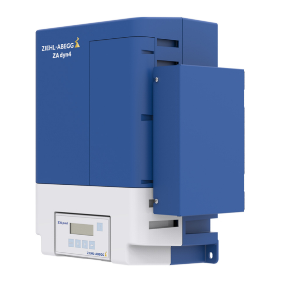
Technical Information Content Safety instructions ............Product overview . -
Page 3: Safety Instructions
Technical Information Safety instructions 1 Safety instructions This technical information sheet contains additional information on the ZAdyn4C operating instructions (R-TBA12_01). Observe the ZAdyn4C operating instructions. Danger! It is forbidden to carry out work on electrically live parts. In frequency inverters of the ZETADYN and ZAdyn type, the intermediate circuit (terminals ZK+ / ZK- or +DC / -DC) are still under voltage even after switching off. -
Page 4: Dimensions
Technical Information Dimensions 3 Dimensions R-TIA19_02-D-GB 1942 Part.-No. 00163469-D-GB 4/26... -
Page 5: Saving The Parameter Values Of The Zetadyn 3C
Technical Information Saving the parameter values of the ZETADYN 3C 4 Saving the parameter values of the ZETADYN 3C In order to continue operating the elevator with the same travel properties, the same parameter settings must be made on the ZAdyn4C as on the ZETADYN 3C. The parameter values of the ZETADYN 3C must therefore be saved. -
Page 6: Mechanical Installation
Technical Information Mechanical installation 5 Mechanical installation General notes Danger! It is forbidden to carry out work on electrically live parts. In frequency inverters of the ZETADYN and ZAdyn type, the intermediate circuit (terminals +DC / -DC) are still under voltage even after switching off. You must wait at least three minutes. - Page 7 Technical Information Mechanical installation " Hook the retrofit kit with the openings at the side (7) into the top hooks on the fastening plate (6). Press the retrofit kit down carefully until it is touching. " Remove the retrofit kit cover. "...
-
Page 8: Assembly On The Zadyn4C 040-074
Technical Information Mechanical installation Assembly on the ZAdyn4C 040-074 " Insert the hook (1) of the fastening plate in the openings (2) on the right side of the ZAdyn4C. Ensure here that the chamfer (3) of the fastening plate is on the right side. The press-in nut (4) of the fastening plate grips the elongated hole (5) in the side of the ZAdyn4C. - Page 9 Technical Information Mechanical installation Hook the retrofit kit with the openings at the side (8) into the top hooks on the fastening plate (7). " Press the retrofit kit down carefully until it is touching. Remove the retrofit kit cover. "...
-
Page 10: Electrical Installation
Technical Information Electrical installation 6 Electrical installation General information Danger! It is forbidden to carry out work on the frequency inverter when it is live. Even after disconnection, the DC-link ( terminals X2: +DC / X2:-DC ) is still live. Wait at least 3 minutes before working on the device Attention! Parts can be destroyed by electrostatic discharge. -
Page 11: Connecting Connecting Cables On The Retrofit Kit
Technical Information Electrical installation If necessary, the ends can be secured with a strip of insulation tape. The tape is self-bonding; the " overlap causes the layers of the tape to join. Connecting connecting cables on the retrofit kit 6.3.1 Replacement of the connector on the X-K connecting lead Before connection to the retrofit kit, the connector on the X-K connecting cable must be replaced. - Page 12 Technical Information Electrical installation Connect wires 1-4 and 5-13 to the connectors supplied (3). The wires are numbered and there are " matching numbers on the connectors. If the wire designations are difficult to read, it is useful to reconnect the wires individually in turn. R-TIA19_02-D-GB 1942 Part.-No.
-
Page 13: Connection
Technical Information Electrical installation 6.3.2 Connection Lead Connection terminal on retrofit kit Brake monitoring X-BR PWM/+24V The 2-core cable for the temperature mon- itoring of the brake resistor, which is con- nected to the PINs 24V and PWM on the ZETADYN 3C, is connected to the retrofit kit on the X-PWM connection terminal. -
Page 14: Strain Relief
Technical Information Electrical installation 6.3.3 Strain relief Cable ties must be attached to all connecting cables for strain relief. The cable ties must be fixed to the recesses provided on the housing of the retrofit kit (see figure in the chapter "Connecting connecting cables on the retrofit kit/Connection"). -
Page 15: Removing Coding
Technical Information Electrical installation Removing coding Codings must be removed from the following plug connections so that the plug connections can be plugged into the sockets of the ZAdyn4C: Cable/plug connection X-BC 1, 2 X-EXT Removing coding, e.g.: PIN 1 and 2 on connector X-BC Connecting connecting cables on the ZAdyn4C The connecting cables which are connected to the connection terminals listed in the following tables are removed from the ZETADYN 3C and connected directly to the ZAdyn4C. - Page 16 Technical Information Electrical installation Plug connections are connected to the connection terminals listed in the following table. ZETADYN 3C ZAdyn4C Temperature monitoring brake Temperature monitoring brake chopper/brake resistor (X-BC) chopper/brake resistor (X-MON) 1 (-)* -> The 2-core cable for the temperature monitoring of the brake resistor, which is connected to the PINs +24V and PWM on the ZETADYN 3C, is con-...
- Page 17 Technical Information Electrical installation ZETADYN 3C ZAdyn4C Digital inputs (X-I) Digital inputs (X-IN) +24V -> +24V +24V_IN -> +24V_IN -> -> -> -> -> -> -> -> GND_IN -> GND_IN -> Shielding -> Shielding Encoder simulation (X-ENCO) Encoder simulation (X-ENCO) Shielding ->...
-
Page 18: Start-Up
Technical Information Start-up 7 Start-up General information For details of commissioning the ZAdyn4C, refer to the “Commissioning” chapter in the ZAdyn4C operating instructions. If the absolute value encoder cable length is greater than 5 m, the operating voltage of the absolute value encoder has to be checked. - Page 19 Technical Information Configuring the ZAdyn4C Parameter list "Motor name plate" menu f_O1 MOT_TYP (Motor Typ) f_O2 (rpm) f_O3 (Hz) f_O4 f_PWM/f_O5 V_G1 V_G2 (kW) V_G3 cos phi SIM_V1 A_MAX M_MAX S_B_OFF Encoder & BC menu Monitoring menu ENC_TYP MOD_ST ENC_INC BC_TYP LOCKBR R_BR...
-
Page 20: Loading Parameters Onto The Zadyn4C
Technical Information Configuring the ZAdyn4C Acceleration menu T_5a A_POS T_5b R_POS1 R_POS2 Controller menu Travelling menu SPD_KP SPD_TI Menu parameter set 2 F_PAR2 U_ACCU P_UPS RS_UPS STOP Copy Deceleration menu A_NEG Menu encoder calibration (for synchronous motors) R_NEG1 ENC_OFF R_NEG2 S_DI3 Menu CAN (for CAN control) S_DI2... -
Page 21: Enclosure
Technical Information Enclosure Memory Card Select "LOD_PAR" parameter LOD_PAR 0 - " Confirming menu selection - " Enter "LOD_PAR=27" Confirm with the key. The parameters are saved. Please wait ... Copy1:_ _ _ _ _ _ _ 9 Enclosure Technical data Retrofit kit Electrical data Contactor supply voltage... -
Page 22: Connection Diagrams
Technical Information Enclosure Connection diagrams Retrofit kit circuit suggestion on ZAdyn4C R-TIA19_02-D-GB 1942 Part.-No. 00163469-D-GB 22/26... -
Page 23: Eu Declaration Of Conformity
Technical Information Enclosure EU declaration of conformity - Translation - (english) A-KON18_01-GB 1941 Index 002 Manufacturer ZIEHL-ABEGG SE Heinz-Ziehl-Straße 74653 Künzelsau Germany The manufacturer shall bear sole responsibility for issuing this EU declaration of conformity. Product description: Retrofit kit Type:... - Page 24 Enclosure The authorised representative for the assembly of the technical file is: Mr. Roland Hoppenstedt (see above for address). Künzelsau, 09.10.2019 (location, date of issue) ZIEHL-ABEGG SE ZIEHL-ABEGG SE Werner Bundscherer Roland Hoppenstedt Director Drive Division Technical Director Drive Division...
- Page 25 Technical Information Enclosure R-TIA19_02-D-GB 1942 Part.-No. 00163469-D-GB 25/26...
- Page 26 Customer Service phone +49 7940 16-308 +49 7940 16-249 drives-service@ziehl-abegg.com Headquarters Ziehl-Abegg AG Heinz-Ziehl-Straße · 74653 Künzelsau Germany phone Tel. +49 (0) 7940 16-0 · fax Fax +49 (0) 7940 16-249 drives@ziehl-abegg.de www.ziehl-abegg.com...
Need help?
Do you have a question about the ZETADYN 3C-ZAdyn4C and is the answer not in the manual?
Questions and answers