
Related Manuals for Kontron Qseven-Eval Carrier


Summary of Contents for Kontron Qseven-Eval Carrier
- Page 1 USER GUIDE QSEVEN-Eval Carrier Doc. Rev. 1.1 Doc. ID: 1062-1574 www.kontron.com // 1...
- Page 2 QSEVEN-Eval Carrier - Rev. 1.1 This page has been intentionally left blank www.kontron.com // 2...
- Page 3 In cases of doubt, please contact Kontron. This user guide is protected by copyright. All rights are reserved by Kontron. No part of this document may be reproduced, transmitted, transcribed, stored in a retrieval system, or translated into any language or computer language, in any form or by any means (electronic, mechanical, photocopying, recording, or otherwise), without the express written permission of Kontron.
- Page 4 SEVERE PHYSICAL OR ENVIRONMENTAL DAMAGE (COLLECTIVELY, "HIGH RISK APPLICATIONS"). You understand and agree that your use of Kontron devices as a component in High Risk Applications is entirely at your risk. To minimize the risks associated with your products and applications, you should provide adequate design and operating safeguards.
- Page 5 If you have any difficulties using this user guide, discover an error, or just want to provide some feedback, contact Kontron support. Detail any errors you find. We will correct the errors or problems as soon as possible and post the revised user guide on our website.
-
Page 6: Symbols
QSEVEN-Eval Carrier - Rev. 1.1 Symbols The following symbols may be used in this user guide. DANGER indicates a hazardous situation which, if not avoided, will result in death or serious injury. WARNING indicates a hazardous situation which, if not avoided, could result in death or serious injury. -
Page 7: For Your Safety
Therefore, in the interest of your own safety and of the correct operation of your new Kontron product, you are requested to conform with the following guidelines. -
Page 8: Lithium Battery Precautions
General Instructions on Usage In order to maintain Kontron’s product warranty, this product must not be altered or modified in any way. Changes or modifications to the product, that are not explicitly approved by Kontron and described in this user guide or received from Kontron Support as a special handling instruction, will void your warranty. -
Page 9: Table Of Contents
QSEVEN-Eval Carrier - Rev. 1.1 Table of Contents Symbols ..........................................6 For Your Safety ........................................7 High Voltage Safety Instructions ................................. 7 Special Handling and Unpacking Instruction ............................7 Lithium Battery Precautions ..................................8 General Instructions on Usage ..................................8 Quality and Environmental Management .............................. -
Page 10: List Of Tables
QSEVEN-Eval Carrier - Rev. 1.1 7.19. Micro-SD Card Connector (J56) ................................. 45 7.20. COM Connector (J58) ................................... 45 7.21. CAN Connector (J57) ....................................46 7.22. LPC/GPIO Header (J59) ..................................46 7.23. Power Management Header (J62) ..............................47 7.24. SYS Signals Header (J37) ..................................47 7.25. - Page 11 QSEVEN-Eval Carrier - Rev. 1.1 Table 12: Connector Definitions .................................. 27 Table 13: QSEVEN Connector Pin Assignment ............................28 Table 14: 30-pin LVDS connector ................................31 Table 15: 7-pin Backlight Connector ................................32 Table 16: Dual Stacked DP Connector ............................... 32 Table 17: 19-pin HDMI connector ................................
-
Page 12: List Of Figures
Table 70: TACHOIN CPU Fan/SYS Fan (J68) ............................56 Table 71: List of Acronyms ..................................... 57 List of Figures Figure 1: Block Diagram for the QSEVEN-EVAL Carrier ........................16 Figure 2: Qseven Module Power Setting Resistors ..........................16 Figure 3: Top View ......................................20 Figure 4: Rear View ...................................... -
Page 13: 1/ Introduction
QSEVEN-Eval Carrier - Rev. 1.1 1/ Introduction This user guide describes the Qseven-Eval carrier board. This document describes the electronic, mechanical and thermal design of the QSEVEN evaluation carrier board. It is designed to test the Qseven-Q7AL and other QSEVEN 2.1 modules. -
Page 14: 2/ Product Description
QSEVEN-Eval Carrier - Rev. 1.1 2/ Product Description The Qseven-Eval Carrier Board designed based on the latest QSEVEN design guide version 2.0 is equipped with: DP++ connector HDMI connector Dual stacked Display Port LVDS connector ... -
Page 15: 3/ Installation Procedure
QSEVEN-Eval Carrier - Rev. 1.1 3/ Installation Procedure 3.1. Packing Check List The package includes the following basic items accompany with this user guide. One Board If this item is either damaged or missing, please contact your vendor and save all packing materials for future replacement and maintenance. -
Page 16: 4/ Product Specification
QSEVEN-Eval Carrier - Rev. 1.1 4/ Product Specification 4.1. Block Diagram Figure 1: Block Diagram for the QSEVEN-EVAL Carrier To power the Qseven Module the power can be set to Ext/Int power by populating one of the following resistors. ... -
Page 17: 4.2. Component Main Data
QSEVEN-Eval Carrier - Rev. 1.1 4.2. Component Main Data The table below summarizes the features of the motherboard. Table 1: Component Main Data Qseven-Eval Carrier Form factor Carrier board with 210 mm x 200 mm. Memory EEPROM System The EEPROM type 24LC64 on carrier board connected to QSEVEN GP I2C or SM bus. - Page 18 QSEVEN-Eval Carrier - Rev. 1.1 LEDs SMD LEDs for storage activity, board status, device and power status (power good) Internal Header and Jumper GPIO/LPC GPIO/LPC Header 2.54 mm Power 2.54 mm pin header, dual row Management Header SYS Signals Header 2.54 mm pin header, dual row...
-
Page 19: 4.3. Environmental Conditions And Standard & Approvals
QSEVEN-Eval Carrier - Rev. 1.1 4.3. Environmental Conditions and Standard & Approvals The Qseven-Eval Carrier plan to comply with the following standards. Table 2: Environmental Conditions and Standard & Approvals Operating -40°C to +85°C Storage -40°C to +85°C Relative humidity (non-condensing) 93 % at 40°C... -
Page 20: 4.4. Mainboard View And I/O Locations
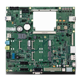
QSEVEN-Eval Carrier - Rev. 1.1 4.4. Mainboard View and I/O Locations Figure 3: Top View QSeven Connector (J1) Button switches ( reset, sleep, power, LID) CPU fan (J60) 10 Power Management Header (J62) System fan(J61) 11 LPC/GPIO header (J59) SATA Connector (J55) -
Page 21: Figure 4: Rear View
QSEVEN-Eval Carrier - Rev. 1.1 Figure 4: Rear View Figure 5: Front View CAN connector (J57) ATX connector (J20) PCIE connector (J41) Power-In Connector (J21) COM connector(J58) Module Power-In connector (J64) www.kontron.com // 21... -
Page 22: Figure 6: Right Side View
QSEVEN-Eval Carrier - Rev. 1.1 Figure 6: Right Side View HDMI (J4) LVDS Connector (J23) DP (J3) Backlight connector (J32) Dual stack DP (J2) LAN (RJ45) Connector (J33) Figure 7: Left Side View USB 2.0 (J22) Backlight Connector (J32) Double USB 3.0 (J34) Audio Jacks (J38, J39) www.kontron.com... -
Page 23: 5/ Jumpers And Connectors
QSEVEN-Eval Carrier - Rev. 1.1 5/ Jumpers and Connectors This chapter gives the definitions and shows the positions of jumpers, headers and connectors. All of the configuration jumpers on the board are in the proper positionHardware Configuration Setting In general, jumpers on the board are used to select options for certain features. Some of the jumpers are designed to be user-configurable, allowing for system enhancement. - Page 24 QSEVEN-Eval Carrier - Rev. 1.1 Connector Function Remark Backlight (J32) via jumper. 1x7 pins HDMI (J4) HDMI connector from QSEVEN module standard DP++ (J3) Display port connector from QSEVEN module standard PCIe x1 (J40/J41) 2x PCIe 1x slot standard mPCIe (J45/J46) 2x card slot (full size / half size) - PCIe &...
-
Page 25: 6/ Maintenance And Status Information
QSEVEN-Eval Carrier - Rev. 1.1 6/ Maintenance and Status Information 6.1. LEDs Figure 8: Power LEDs Power LEDs Watchdog LEDs Table 4: Power LEDs LED Color Signal Diode Function Green V_1V8_S5 Voltage V_1V8_S5 is present Green V_1V8_S0 Voltage V_1V8_S0 is present... -
Page 26: Table 7: Gpio Leds
QSEVEN-Eval Carrier - Rev. 1.1 Table 7: GPIO LEDs LED Color Signal Diode Function Blue GPIO0 GPIO0 level indication Blue GPIO1 GPIO1 level indication Blue GPIO2 GPIO2 level indication Blue GPIO3 GPIO3 level indication Blue GPIO4 GPIO4 level indication Blue... -
Page 27: 7/ Pin Definitions
QSEVEN-Eval Carrier - Rev. 1.1 7/ Pin Definitions The following sections provide pin definitions and detailed description of all on-board connectors. The connector definitions follow the following notation: Table 12: Connector Definitions Column Name Description Shows the pin-numbers in the connector. The graphical layout of the connector definition tables is made similar to the physical connectors. -
Page 28: Qseven Connector (J1)
QSEVEN-Eval Carrier - Rev. 1.1 7.1. QSEVEN Connector (J1) The QSEVEN connector is MXM 230-pin connector, with the same pins on both sides: Top side: 103 pins are on the left side, 12 pins on the right side ... - Page 29 QSEVEN-Eval Carrier - Rev. 1.1 Pin.No Pin Name (Bottom side row) Pin.No Pin Name (Top side row) THRMTRIP# WDOUT USB_P7- / USB_SSTX0- USB_P6- / USB_SSRX0- USB_P7+ / USB_SSTX0+ USB_P6+ / USB_SSRX0+ USB_6_7_OC# USB_4_5_OC# USB_P5- / USB_SSTX2- USB_P4- / USB_SSRX2- USB_P5+ / USB_SSTX2+...
- Page 30 QSEVEN-Eval Carrier - Rev. 1.1 Pin.No Pin Name (Bottom side row) Pin.No Pin Name (Top side row) PCIE_CLK_REF+ PCIE_WAKE# PCIE_CLK_REF- PCIE_RST# PCIE3_TX+ PCIE3_RX+ PCIE3_TX- PCIE3_RX- PCIE2_TX+ PCIE2_RX+ PCIE2_TX- PCIE2_RX- UART0_TX UART0_RTS# PCIE1_TX+ PCIE1_RX+ PCIE1_TX- PCIE1_RX- UART0_RX UART0_CTS# PCIE0_TX+ PCIE0_RX+ PCIE0_TX-...
-
Page 31: Lvds Connector (J23)
QSEVEN-Eval Carrier - Rev. 1.1 7.2. LVDS Connector (J23) This connector provides data and power connection between the Carrier Board and the Display. This 30-pin lockable connector contains the LVDS output signals and the power to the LVDS display. Note: Pin 1 and pin 32 shields and are not included in the table below. -
Page 32: Backlight Connector (J32)
QSEVEN-Eval Carrier - Rev. 1.1 7.3. Backlight Connector (J32) Figure 11: 7-pin Backlight Connector Table 15: 7-pin Backlight Connector Signal Type Backlight Brightness 5V or 3.3V (jumper selection J24) PWM (0% Out (27.4 Ohm series resistor) - 100%) Ground V_BKLT - 12V or 5.0V (jumper selection J25) Power V_BKLT - 12V or 5.0V (max. - Page 33 QSEVEN-Eval Carrier - Rev. 1.1 Signal Description ML_Lane1-_TOP ML_Lane2+_TOP GND_P8 ML_Lane2-_TOP ML_Lane3+_TOP GND_P11 ML_Lane3-_TOP CONFIG CONFIG1_TOP CONFIG CONFIG2_TOP AUX_CH+_TOP GND_P16 AUX_CH-_TOP HOT_PLUG_TOP RETURN_TOP DP_PWR_TOP ML_Lane0+_BOT GND_P2 ML_Lane0-_BOT ML_Lane1+_BOT GND_P5 ML_Lane1-_BOT ML_Lane2+_BOT GND_P8 ML_Lane2-_BOT ML_Lane3+_BOT GND_P11 ML_Lane3-_BOT CONFIG CONFIG1_BOT CONFIG CONFIG2_BOT...
-
Page 34: Hdmi Connector (J4)
QSEVEN-Eval Carrier - Rev. 1.1 7.5. HDMI connector (J4) Figure 13: 19-pin HDMI connector Table 17: 19-pin HDMI connector Signal TMDS Data2+ TMDS Data2 Shield TMDS Data2− TMDS Data1+ TMDS Data1 Shield TMDS Data1− TMDS Data0+ TMDS Data0 Shield TMDS Data0−... -
Page 35: Dp Connector (J3)
QSEVEN-Eval Carrier - Rev. 1.1 7.6. DP connector (J3) Figure 14: 20-pin DP connector Table 18: 20-pin DP connector Signal Signal ML LANE 0+ GND (ML LANE 0) ML LANE 0- ML LANE 1+ GND (ML LANE 1) ML LANE 1-... -
Page 36: Mini Pcie Card Socket 0 (J45) & Mini Pcie Card Socket 1 (J46)
QSEVEN-Eval Carrier - Rev. 1.1 7.7. Mini PCIe Card Socket 0 (J45) & Mini PCIe Card Socket 1 (J46) Figure 15: 52-pin Mini PCIe Card Table 19: 52-pin Mini PCIe Card Signal Signal WAKE# +3.3V_S5 N.C. N.C. +1.5V_S0 CLKREQ# UIM-PWR... -
Page 37: Sim Card Socket (J53)
QSEVEN-Eval Carrier - Rev. 1.1 8.8. SIM card socket (J53) Figure 16: 8-pin SIM card socket Table 20: 8-pin SIM card socket Signal UIM_PWR UIM_RST UIM_CLK UIM_IC + / NC UIM_VPP / NC UIM_DATA UIM_IC - / NC 7.9. PCIe x1 connectors (J40, J41) -
Page 38: Mini Sata Card Socket (J54)
QSEVEN-Eval Carrier - Rev. 1.1 Signal Signal PERST# WAKE# RSVD – N.C. REFCLK+ REFCLK- PET0+ PET0- PER0+ PER0- PRSNT2# 7.10. Mini SATA Card Socket (J54) Figure 18: 52-pin SATA Card Socket Table 22: 52-pin SATA Card Socket Signal Signal WAKE# +3.3V_S5... -
Page 39: Sata Connector (J55)
QSEVEN-Eval Carrier - Rev. 1.1 7.11. SATA Connector (J55) Figure 19: SATA Connector Table 23: SATA Connector Signal SATA_RDRV_TX1_+ SATA_RDRV_TX1_- SATA_RDRV_RX1_- SATA_RDRV_RX1_+ 7.12. Audio Connector Line In & Out (J38 & J39) Figure 20: Audio Jacks Table 24: Audio Jacks Pin Assignment (Line Out, green) -
Page 40: Audio Connector (J36)
QSEVEN-Eval Carrier - Rev. 1.1 7.13. Audio Connector (J36) Figure 21: 9-pin Audio Connector Header Table 26: 9-pin Audio Connector Header Signal Signal MIC_L AGND MIC_R PRESENCE# LINE_R MIC_JD SENSE LINE_L LINE_JD 7.14. RTC battery holder (J65) Figure 22: RTC battery holder... -
Page 41: Usb 2.0 Otg Connector (J22)
QSEVEN-Eval Carrier - Rev. 1.1 7.15. USB 2.0 OTG Connector (J22) Figure 23: µUSB 2.0 OTG Connector Table 28: µUSB 2.0 OTG Connector Signal +5 V USB output (500 mA max.) USB Data - USB Data + Ground 7.16. USB Hub Connections (J34) Connector J34 implements an industry standard USB dual Type A host connection. -
Page 42: Table 30 : Usb 3.0 Pin Description
QSEVEN-Eval Carrier - Rev. 1.1 Table 30 : USB 3.0 Pin Description Signal Description USBn+ USBn- Differential pair works as serial differential receive/transmit data lines. (n= 0,1,2,3) RXn+ RXn- TXn+ TXn- 5 V / SB5 V 5 V supply for external devices. -
Page 43: Double Usb 3.0 Connector (J34)
QSEVEN-Eval Carrier - Rev. 1.1 7.17. Double USB 3.0 Connector (J34) This connector provides two USB 3.0 connections (downstream). The 5 V output is electronically fused to 1000 mA each port. Figure 25: Double USB 3.0 Connector Table 31: Double USB 3.0 Connector... -
Page 44: Lan Connector (J33)
QSEVEN-Eval Carrier - Rev. 1.1 7.18. LAN Connector (J33) This connector provides an isolated Ethernet 1000Base-T port, which is connected to an on-board LAN Controller. The galvanic isolated transformers (1500 Vrms, Voltage Regulator Module (VRM)) are integrated in the LAN connectors. -
Page 45: Micro-Sd Card Connector (J56)
QSEVEN-Eval Carrier - Rev. 1.1 7.19. Micro-SD Card Connector (J56) Figure 27: Micro-SD Card Connector Table 35: Micro-SD Card Connector Signal SD_DAT[2] CD / SD_DAT[3] SD_CLK GND / VSS SD_DAT[0] SD_DAT[1] CD_DETECT CD_GND SH_GND SH_GND SH_GND SH_GND 7.20. COM Connector (J58) -
Page 46: Can Connector (J57)
QSEVEN-Eval Carrier - Rev. 1.1 7.21. CAN Connector (J57) Figure 29: CAN Connector Table 37: CAN Connector Signal CAN0_L CAN0_H V_5V0 7.22. LPC/GPIO Header (J59) Figure 30: LPC/GPIO Header Table 38: LPC/GPIO Header Signal Signal GPIO4/LPC_CLK GPIO5/LPC_FRAME# N.C. LPC_RST# VCC 5.0V... -
Page 47: Power Management Header (J62)
QSEVEN-Eval Carrier - Rev. 1.1 7.23. Power Management Header (J62) Figure 31: Power Management Header Table 39: Power Management Header Signal Signal VCC 1.8V VCC 3.3V PWGIN SUS_S3# GPO0(SUS_STAT#) SLP_BTN# LID_BTN# PWRBTN# PLT_RST# RSTBTN# BATLOW# GP0_I2C_DAT GP0_I2C_CLK SMB_ALERT# NOTE: SUS_STAT# is changed to GPO0 in Qseven Spec V2.1 7.24. -
Page 48: Thermal Header (J66)
QSEVEN-Eval Carrier - Rev. 1.1 7.25. Thermal Header (J66) Figure 33: Thrm Header Table 41: Thrm Header Signal THRM# THRMTRIP# 7.26. CPU Fan (J60) Figure 34: 4-pin CPU Fan Connector Table 42: 4-pin CPU Fan Connector Signal Description V_CPU_FAN_S0 12 V by default. Can optionally be changed to 5 V, via jumper H16 setting. -
Page 49: Power-In Connector (J21)
QSEVEN-Eval Carrier - Rev. 1.1 7.28. Power-In Connector (J21) Figure 36: Power-In Connector Table 44: Power-In Connector Signal Description V_12V0_IN_CON Main power input for either both module and carrier (default), or for carrier only, when J64 is used. The board can be supplied via the AC/DC adapter plugged into the power jack. Such adapters have usually no connection to protective earth. - Page 50 QSEVEN-Eval Carrier - Rev. 1.1 Location of R468 (V_5V0_S5) the default setting Location of R467 (V_3V0-5V25_IN) www.kontron.com // 50...
-
Page 51: Atx 24 Pin Connector (J20)
QSEVEN-Eval Carrier - Rev. 1.1 7.30. ATX 24 Pin Connector (J20) Figure 38: ATX 24 Pin Connector Table 46: ATX 24 Pin Connector Signal Signal V_3V3_ATX_S0 V_3V3_ATX_S0 V_3V3_ATX_S0 V_3V3_ATX_S0 V_5V0_ATX_S0 PS_ON# V_5V0_ATX_S0 PG_ATX N.C. V_5V0_SB_ATX V_5V0_ATX_S0 V_12V0_ATX_S0 V_5V0_ATX_S0 V_12V0_ATX_S0 V_5V0_ATX_S0 V_3V3_ATX_S0 7.31. -
Page 52: Table 49: Sleep Button (Sw3, J15)
QSEVEN-Eval Carrier - Rev. 1.1 SHIELD Table 49: Sleep Button (SW3, J15) Signal SLP_BTN# SLP_BTN# SHIELD Table 50: Lid Button (SW4, J16) Signal LID_BTN# LID_BTN# SHIELD www.kontron.com // 52... -
Page 53: 7.32. Jumpers
QSEVEN-Eval Carrier - Rev. 1.1 7.32. Jumpers 7.32.1. Boot Alternate Jumper (J14) There is a Jumper for Boot Alternate according to the QSEVEN 2.1 specification. Table 51: Boot Alternate Jumper (J14) Configuration J14 Jumper Setting Boot Source Boot from Carrier SPI Flash N.C. -
Page 54: Audio Channel Jumper For I2S Or Hda (J35)
QSEVEN-Eval Carrier - Rev. 1.1 7.32.6. Audio Channel Jumper for I2S or HDA (J35) Table 56: Audio Channel Jumper for I2S or HDA (J35) Jumper Position Function Description I2S Codec NC (Default) HDA codec 7.32.7. mPCIe-0WLAN Disable Jumper (J5,J6) Table 57: mPCIe-0WLAN Disable Jumper (J5,J6) -
Page 55: Cpu Fan Power Selection Jumper (J30)
QSEVEN-Eval Carrier - Rev. 1.1 7.32.12. CPU Fan Power Selection Jumper (J30) Table 62: CPU Fan Power Selection Jumper (J30) Jumper Position Function Description V_CPU_FAN_S0 = 5V 2-3 (Default) V_CPU_FAN_S0 = 12V 7.32.13. SYS Fan Power Selection Jumper (J29) Table 63: SYS Fan Power Selection Jumper (J29) -
Page 56: Rtc Jumper (J31)
QSEVEN-Eval Carrier - Rev. 1.1 7.32.18. RTC Jumper (J31) Table 68: RTC Jumper (J31) Jumper Position Function Description 1-2 (Default) Module RTC powered by Battery (J65) Module RTC powered by Super Cap (C367) 7.32.19. Module Standby Voltage (J67) Table 69: Module Standby Voltage (J67... -
Page 57: Appendix A: List Of Acronyms
QSEVEN-Eval Carrier - Rev. 1.1 Appendix A: List of Acronyms Table 71: List of Acronyms BIOS Basic Input Output System Industry Standard Architecture Board Support Package Local Area Network Controller-area network Low Pin-Count Interface: Carrier Application specific circuit board that LVDS Low Voltage Differential Signaling –... -
Page 58: About Kontron
QSEVEN-Eval Carrier - Rev. 1.1 About Kontron Kontron is a global leader in embedded computing technology (ECT). As a part of technology group S&T, Kontron offers a combined portfolio of secure hardware, middleware and services for Internet of Things (IoT) and Industry 4.0 applications.
Need help?
Do you have a question about the Qseven-Eval Carrier and is the answer not in the manual?
Questions and answers