
Related Manuals for Kontron COM-HPC


Summary of Contents for Kontron COM-HPC
- Page 1 User Guide COM-HPC Client Evaluation Carrier (L112) User Guide Rev. 1.0 Doc. ID 1070-0149 www.kontron.com...
- Page 2 COM-HPC Client Evaluation Carrier – User Guide Rev. 1.0 This page has been intentionally left blank www.kontron.com // 2...
- Page 3 In cases of doubt, please contact Kontron. This user guide is protected by copyright. All rights are reserved by Kontron. No part of this document may be reproduced, transmitted, transcribed, stored in a retrieval system, or translated into any language or computer language, in any form or by any means (electronic, mechanical, photocopying, recording, or otherwise), without the express written permission of Kontron.
- Page 4 (collectively, “high risk applications”). You understand and agree that your use of Kontron devices as a component in High Risk Applications is entirely at your risk. To minimize the risks associated with your products and applications, you should provide adequate design and operating safeguards.
- Page 5 Kontron sells products worldwide and declares regional General Terms & Conditions of Sale, and Purchase Order Terms & Conditions. Visit www.kontron.com/terms-and-conditions. For contact information, refer to the corporate offices contact information on the last page of this user guide or visit...
-
Page 6: Symbols
COM-HPC Client Evaluation Carrier – User Guide Rev. 1.0 Symbols The following symbols may be used in this user guide DANGER indicates a hazardous situation which, if not avoided, will result in death or serious injury. WARNING indicates a hazardous situation which, if not avoided, could result in death or serious injury. -
Page 7: For Your Safety
Therefore, in the interest of your own safety and of the correct operation of your new Kontron product, you are requested to conform with the following guidelines. -
Page 8: Lithium Battery Precautions
General Instructions on Usage In order to maintain Kontron’s product warranty, this product must not be altered or modified in any way. Changes or modifications to the product, that are not explicitly approved by Kontron and described in this user guide or received from Kontron Support as a special handling instruction, will void your warranty. -
Page 9: Table Of Contents
COM-HPC Client Evaluation Carrier – User Guide Rev. 1.0 Table of Contents Symbols ..................................6 For Your Safety ................................7 High Voltage Safety Instructions ........................... 7 Special Handling and Unpacking Instruction ......................7 Lithium Battery Precautions ..........................8 General Instructions on Usage ............................8 Quality and Environmental Management ........................ - Page 10 COM-HPC Client Evaluation Carrier – User Guide Rev. 1.0 5.29. IPMB Header (J4) ............................37 5.30. LCD Panel Voltage Selection Jumper (J22, H4) ................... 37 5.31. eDP Self Test Header (J18) ......................... 37 5.32. Miscellaneous (J26) ............................ 38 5.33. Clock Buffer Jumpers X4 (J111, H26) and x8 (J112, H27) ................38 5.34.
-
Page 11: List Of Tables
COM-HPC Client Evaluation Carrier – User Guide Rev. 1.0 List of Tables Table 1: Features ................................. 15 Table 2: Component Main Data ..........................17 Table 3: Environmental Conditions ..........................17 Table 4: NBase-T/USB Combo Connectors (J102, J103) ....................23 Table 5: Display Ports (J27, J96) ..........................23 Table 6: Front USB-C Ports (J101, J100) ........................ -
Page 12: List Of Figures
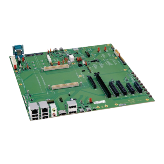
Figure 1: COM-HPC Client Evaluation Carrier (ADHC) ....................14 Figure 2: Block Diagram COM-HPC Client Evaluation Carrier (ADHC) ................. 18 Figure 3: Top View of COM-HPC Client Evaluation Carrier (ADHC) ................19 Figure 4: Front IOs ............................... 20 Figure 5: Rear IOs ................................ 21 Figure 6: Board Dimensions and Jumper Positions ..................... - Page 13 COM-HPC Client Evaluation Carrier – User Guide Rev. 1.0 Figure 45: ATX Power connector with 24 pins (J16) ....................42 Figure 46: ATX-ON Jumper (J20, H1) ........................... 42 Figure 47: ATX Power connector with 8 pins ......................43 Figure 48: RTC Battery Socket (J21) ..........................43 Figure 49: External RTC Battery Connector (J78) ......................
-
Page 14: 1/ Introduction
COM-HPC® modules in ATX form factor. The ADHC will allow more flexibility with respect to the 10 GbE configurations. Main purpose of this carrier board is to bring out all the signals from COM-HPC® connector of COMh modules to industry standard interfaces. The key features are: Support of 64 PCIe lanes via various PCIe and M.2 slots... -
Page 15: Product Naming Clarification
All Kontron COM-HPC® extended, basic and compact modules contain two 2x 100pin connectors; each of it has two rows called Row A & B on primary connector and Row C & D on secondary connector. The COM-HPC® Computer-On- Module (COM) features the following maximum amount of interfaces according to the PCI Industrial Computer Manufacturers Group (PICMG) module Pin-out type. -
Page 16: Com-Hpc® Documentation
COM-HPC® modules are compact and highly integrated computers. All modules feature a standardized form factor and connector layout which carry a specified set of signals. Each COM is based on the COM-HPC® specification. This standardization allows designers to create a single-system baseboard that can accept present and future COM-HPC®... -
Page 17: 2/ System Specifications
COM-HPC Client Evaluation Carrier – User Guide Rev. 1.0 2/ System specifications 2.1. Component Main Data The table below summarizes the features of the motherboard. Table 2: Component Main Data COM-HPC Client Evaluation Carrier (ADHC) Size D and E Dimensions... -
Page 18: Block Diagram
COM-HPC Client Evaluation Carrier – User Guide Rev. 1.0 2.3. Block diagram Figure 2: Block Diagram COM-HPC Client Evaluation Carrier (ADHC) // 18 www.kontron.com... -
Page 19: 3/ Mainboard Views
COM-HPC Client Evaluation Carrier – User Guide Rev. 1.0 3/ Mainboard Views 3.1. Top View Figure 3: Top View of COM-HPC Client Evaluation Carrier (ADHC) 1. Front Panel (J11) 9. SMB (J5) 2. Boot SPI Connector (J113) 10. I2C1 (J8) 3. -
Page 20: Ios
COM-HPC Client Evaluation Carrier – User Guide Rev. 1.0 17. USB-C 5V S5/S0 Jumper (J120) 33. 2x M.2 (J85, J86) 18. FUSA Header (J116) 34. 2x SATA (J87, J88) 19. Audio Header (J122) 35. LCD Panel Voltage Selection Jumper (J22, H4) 20. -
Page 21: Figure 5: Rear Ios
COM-HPC Client Evaluation Carrier – User Guide Rev. 1.0 Figure 5: Rear IOs 54. 2x USB Type-C (J98, J99) 55. 2x COM ports (J94) // 21 www.kontron.com... -
Page 22: 4/ Mechanical Specification
COM-HPC Client Evaluation Carrier – User Guide Rev. 1.0 4/ Mechanical Specification 4.1. Dimensions and Jumper Positions The dimensions of the carrier board are 305.0 mm x 330.0 mm. Figure 6: Board Dimensions and Jumper Positions 330 mm J110 J114... -
Page 23: 5/ Interfaces And Connectors
COM-HPC Client Evaluation Carrier – User Guide Rev. 1.0 5/ Interfaces and Connectors 5.1. NBase-T/USB Combo Connectors (J102, J103) Figure 7: NBase-T/USB Combo Connectors (J102, J103) Table 4: NBase-T/USB Combo Connectors (J102, J103) Connector Function Position J102 (Left) NBase-T0 Ethernet Connector... -
Page 24: Front Usb-C Ports (J101, J100)
COM-HPC Client Evaluation Carrier – User Guide Rev. 1.0 5.3. Front USB-C Ports (J101, J100) Figure 9: Front USB-C Ports (J101, J100) Table 6: Front USB-C Ports (J101, J100) Connector Function Position J101 (Left) USB-C Port 3 Left J100 (Right) -
Page 25: Com Ports (J94)
COM-HPC Client Evaluation Carrier – User Guide Rev. 1.0 5.5. COM Ports (J94) Figure 11: Double COM Ports Bottom Table 8: Double COM Ports Signal Name RS232_0_RX_J RS232_0_TX_-J RS232_0_RTS_J# RS232_0_CTS_J# RS232_1_RX_J RS232_1_TX_J RS232_1_RTS_J# RS232_1_CTS_J# // 25 www.kontron.com... -
Page 26: Ethernet Add-In Card Connector (J7)
COM-HPC Client Evaluation Carrier – User Guide Rev. 1.0 5.6. 10 GB Ethernet Add-in Card Connector (J7) The carrier board contains 10 GB Ethernet connector that supports copper and optical 10 GB interface via extended cards. Figure 12: 10 GB Ethernet Add-in Card Connector... -
Page 27: Port 80 Bios Debug Code Display
10G_PHY_MDIO_SDA2 5.7. Port 80 BIOS Debug Code Display COM-HPC Modules may support the export of Port 80 BIOS debug codes over a specific I2C link, the USB_PD_I2C_DAT and CLK bus, to a pair of Carrier based 7-segment displays. Figure 13: Port 80 BIOS Debug Code 7-Segment Display... -
Page 28: Sata 6 Gb (J87, J88)
COM-HPC Client Evaluation Carrier – User Guide Rev. 1.0 5.8. SATA 6 GB (J87, J88) Figure 14: SATA 6 GB Table 10: SATA 6 GB Connectors (J87, J88) Signal Name – J87 Signal Name – J88 SATA0_TX+ SATA1_TX+ SATA0_TX- SATA1_TX-... -
Page 29: Fan Connector (J47)
COM-HPC Client Evaluation Carrier – User Guide Rev. 1.0 5.10. Fan Connector (J47) Figure 15: Fan Connector with 4 pins (J47) Table 12: Fan Connector (J47) Description V_FAN FAN_TACH_CON FAN_PWM_CON 5.11. 4-Pin/3-Pin Fan Jumper (J74, H23) Figure 16: 4-Pin/3-Pin Fan Jumper (J74, H23) -
Page 30: Fusa Header (J116)
COM-HPC Client Evaluation Carrier – User Guide Rev. 1.0 5.13. FUSA Header (J116) Figure 18: FUSA Header (J116) Table 15: FUSA Header (J116) Signal Name Signal Name FUSA_STATUS0 FUSA_STATUS1 FUSA_ALERT# FUSA_SPI_CS# FUSA_SPI_CLK FUSA_SPI_MISO FUSA_SPI_MOSI FUSA_SPI_ALERT FUSA_VOLTAGE_ERR# PROCHOT# CATERR# THERMTRIP# 5.14. M.2 Jumper (J110, H25) Figure 19: M.2 Jumper (J110, H25) -
Page 31: Boot Spi Flash Socket (J19)
COM-HPC Client Evaluation Carrier – User Guide Rev. 1.0 5.16. Boot SPI Flash Socket (J19) Figure 21: Boot SPI Flash Socket (J19) Table 18: Boot SPI Flash Socket Pinout (J19) Signal Signal BOOT_SPI_CS# DIN/IO0 SOUT/IO1 SCLK WP#/IO2 HOLD#/IO3/RST VCC_BOOT_SPI 5.17. ESPI Connector (J14) -
Page 32: Fw Spi Flash Socket (J113)
COM-HPC Client Evaluation Carrier – User Guide Rev. 1.0 5.18. FW SPI Flash Socket (J113) Figure 23: SPI Flash Socket (J113) Table 20: SPI Flash Socket (J113) Signal Name Signal Name BOOT_SPI_CS# VCC_BOOT_SPI BOOT_SPI_IO1 BOOT_SPI_IO3 BOOT_SPI_IO2 BOOT_SPI_CLK BOOT_SPI_IO0 5.19. GPIO - General Purpose Input and Output (J3) The COM-HPC Client Evaluation Carrier offers 20 pins. -
Page 33: Ac Present Jumper (J24, H3)
COM-HPC Client Evaluation Carrier – User Guide Rev. 1.0 5.20. AC Present Jumper (J24, H3) Figure 25: AC Present Jumper (J24, H3) Table 22: AC Present Jumper (J24, H3) Description AC_PRESENT (PU on module) Driven hard low on carrier if system AC power is not present. Default: 1-2 5.21. -
Page 34: Usb-C 5V S5/S0 Jumper (J120, H32)
COM-HPC Client Evaluation Carrier – User Guide Rev. 1.0 5.23. USB-C 5V S5/S0 Jumper (J120, H32) Figure 28: USB-C 5V S5/S0 Jumper (J120, H32) Table 25: USB-C 5V S5/S0 Jumper (J120, H32) Jumper Position Description 5V0_S0 in S0, 5V0_S5 in S5 (default) V_5V0_S5 in S0 and S5 5.24. -
Page 35: Switch 12 (Sw12)
COM-HPC Client Evaluation Carrier – User Guide Rev. 1.0 5.25. Switch 12 (SW12) Figure 30: Switch 12 (SW12) Table 27: Switch 12 (SW12) Switch Position Description Left SNDW1 Right SNDW0 5.26. TEST Header (J13) Figure 31: TEST Header (J13) Table 28: TEST Header (J13) -
Page 36: Csi0, Csi1 Headers (J108, J109)
COM-HPC Client Evaluation Carrier – User Guide Rev. 1.0 5.28. CSI0, CSI1 Headers (J108, J109) Figure 33: CSI0, CSI1 Headers (J108, J109) Table 30: CSI0, CSI1 Headers (J108, J109) Signal Name – J108 Signal Name – J109 CSI0_RX0_J- CSI1_RX0_J- CSI0_RX0_J+... -
Page 37: Ipmb Header (J4)
COM-HPC Client Evaluation Carrier – User Guide Rev. 1.0 5.29. IPMB Header (J4) Figure 34: IPMB Header (J4) Table 31: Pinning IPMB Header (j4) Description V_3V3_S5 IPMB_DAT IPMB _CLK 5.30. LCD Panel Voltage Selection Jumper (J22, H4) Figure 35: LCD Panel Voltage Selection Jumper (J22, H4) -
Page 38: Miscellaneous (J26)
COM-HPC Client Evaluation Carrier – User Guide Rev. 1.0 5.32. Miscellaneous (J26) Figure 37: Miscellaneous (J26) Table 34: Miscellaneous Header (J26) Signal Name Signal Name V_3V3_S5 SUS_S3# PWRBTN# SUS_S4_S5# RSTBTN# NC_MISC PLTRST# WD_OUT VIN_PWR_OK WD_STROBE# BATLOW# NC_MISC THERMTRIP# NC_MISC CARRIER_HOT#... -
Page 39: Front Panel Header (J11)
COM-HPC Client Evaluation Carrier – User Guide Rev. 1.0 5.34. Front Panel Header (J11) Figure 39: Front Panel Connector Table 36: Front Panel Header Signal Name HDLED+ PLED+ HDLED- PLED- PWRBTN# RESET# RSVD 5.35. I2C0 Header (J6) The I2C Interface supports clock from 127Hz to 400kHz (limited by on board devices and capacitive loading) and can be configured in Setup. -
Page 40: I2C1 Header (J8)
COM-HPC Client Evaluation Carrier – User Guide Rev. 1.0 5.36. I2C1 Header (J8) The I2C Interface supports clock from 127Hz to 400kHz (limited by on board devices and capacitive loading) and can be configured in Setup. Figure 41: I2C1 Header (J8) -
Page 41: Gp_Spi Header (J12)
COM-HPC Client Evaluation Carrier – User Guide Rev. 1.0 5.38. GP_SPI Header (J12) Figure 43: GP_SPI Header (J12) Table 40: GP_SPI Header (J12) Signal Name Signal Name V_3V3_S5 GP_SPI_MISO V_3V3_S0 GP_SPI_MOSI PLTRST# GP_SPI_CLK GP_SPI_CS0# GP_SPI_CS1# GP_SPI_ALERT# GP_SPI_CS2# GP_SPI_CS3# 5.39. Mic and Headphone Connector (J15) -
Page 42: Atx Power Connector (J16)
COM-HPC Client Evaluation Carrier – User Guide Rev. 1.0 5.40. ATX Power connector (J16) Figure 45: ATX Power connector with 24 pins (J16) Table 42: ATX Power connector with 24 pins (J16) Signal Name Signal Name +3.3VDC +3.3VDC +3.3VDC +5VDC... -
Page 43: Atx Power Connector (J17)
COM-HPC Client Evaluation Carrier – User Guide Rev. 1.0 5.42. ATX Power connector (J17) Figure 47: ATX Power connector with 8 pins Table 44: ATX Power connector with 8 pins Signal +12 V +12 V +12 V +12 V 5.43. RTC Battery CR2032 Socket (J21) -
Page 44: External Rtc Battery Connector (J78)
COM-HPC Client Evaluation Carrier – User Guide Rev. 1.0 5.44. External RTC Battery Connector (J78) Figure 49: External RTC Battery Connector (J78) Table 46: External RTC Battery Connector (J78) Signal Name V_3V0_RTC 5.45. Button Switches Figure 50: Button Switches Table 47: Button Switches... -
Page 45: Edp Connector (J10)
COM-HPC Client Evaluation Carrier – User Guide Rev. 1.0 5.46. EDP Connector (J10) Figure 51: EDP Connector (J10) Table 48: EDP Connector (J10) Signal Name Signal Name V_LCD_VCC EDP_SELF_TEST_J EDP_TX3_J- EDP_TX3_J+ EDP_TX2_J- EDP_TX2_J+ EDP_HPD_J EDP_TX1_J- EDP_TX1_J+ EDP_TX0_J- EDP_BKLT_EN_J EDP_TX0_J+ EDP_BKLTCTL_J... -
Page 46: Key-M Socket With Spacer (J85, J86)
COM-HPC Client Evaluation Carrier – User Guide Rev. 1.0 5.47. M.2 Key-M Socket with Spacer (J85, J86) Figure 52: M.2 Slot Connector (J85, J86) Table 49: PIN Assignment M.2 Connector (J85) Signal Name Signal Name V_3V3_M2_LOW_S5_S0 V_3V3_M2_LOW_S5_S0 PCIE11_RX- PCIE11_RX+ DAS_M2_LOW#... -
Page 47: Table 50: Pin Assignment M.2 Connector (J86)
COM-HPC Client Evaluation Carrier – User Guide Rev. 1.0 SUS_CLK_M2_LOW V_3V3_M2_LOW_S5_S0 PEDET_M2_LOW(*) Signal Name Signal Name V_3V3_M2_LOW_S5_S0 V_3V3_M2_LOW_S5_S0 (*) To be grounded for SATA, No Connect for PCIe. M.2 SATA not supported! Table 50: PIN Assignment M.2 Connector (J86) Signal Name... -
Page 48: Figure 53: Power Diagram
COM-HPC Client Evaluation Carrier – User Guide Rev. 1.0 Key M Area SUSCLK V_3V3_M2_HIGH_S5_S0 PEDET_M2_HIGH(*) V_3V3_M2_HIGH_S5_S0 Signal Name Signal Name V_3V3_M2_HIGH_S5_S0 (*) To be grounded for SATA, No Connect for PCIe. M.2 SATA not supported! Figure 53: Power Diagram // 48... -
Page 49: 6/ Leds And Indicators
COM-HPC Client Evaluation Carrier – User Guide Rev. 1.0 6/ LEDs and Indicators Indicators and LEDs indicate only presence of voltage on certain signal, but not necessarily a correct shape and level of the voltage. This is important especially for power supplies – power good signal would provide more accurate indication, but it is not possible to provide this for all signals (for example ATX power signals share one power good). -
Page 50: 7/ Com-Hpc Connector Pin-Out List
COM-HPC Client Evaluation Carrier – User Guide Rev. 1.0 7/ COM-HPC Connector Pin-out List Figure 54: COM-HPC Connectors J1 and J2 To protect external power lines of peripheral devices, make sure that: the wires have the right diameter to withstand the maximum available current the enclosure of the peripheral device fulfills the fire-protection requirements of IEC/EN60950. - Page 51 COM-HPC Client Evaluation Carrier – User Guide Rev. 1.0 Primary (lower) Connector J1 Row A Row B Row C Row D DDI1_PAIR0+ VCC_5V_SBY SNDW_DMIC_DAT0 USB67_OC# DDI0_PAIR1- DDI1_PAIR1- USB45_OC# DDI0_DDC_AUX_SEL DDI0_PAIR1+ DDI1_PAIR1+ USB23_OC# DDI1_DDC_AUX_SEL USB01_OC# DDI0_HPD DDI0_PAIR2- DDI1_PAIR2- SML1_CLK DDI1_HPD DDI0_PAIR2+...
- Page 52 COM-HPC Client Evaluation Carrier – User Guide Rev. 1.0 Primary (lower) Connector J1 Row A Row B Row C Row D PCIe08_TX+ PCIe00_RX+ PCIe09_RX- PCIe01_TX- PCIe09_TX- PCIe09_RX+ PCIe01_RX- PCIe01_TX+ PCIe09_TX+ PCIe01_RX+ PCIe10_RX- PCIe02_TX- PCIe10_TX- PCIe10_RX+ PCIe02_RX- PCIe02_TX+ PCIe10_TX+ PCIe02_RX+ PCIe11_RX-...
-
Page 53: Table 53: Pin-Out List Connector J2
COM-HPC Client Evaluation Carrier – User Guide Rev. 1.0 Table 53: Pin-out List Connector J2 Secondary (upper) Connector J2 Row E Row F Row G Row H RAPID_SHUTDOWN RSVD RSVD RSVD USB2_SSTX0- DDI2_SDA_AUX- RSVD USB2_SSRX0- USB2_SSTX0+ DDI2_SCL_AUX+ RSVD USB2_SSRX0+ RSVD... - Page 54 COM-HPC Client Evaluation Carrier – User Guide Rev. 1.0 Secondary (upper) Connector J2 Row E Row F Row G Row H PCIe38_TX- PCIe38_RX+ PCIe46_RX- PCIe46_TX+ PCIe38_TX+ PCIe46_RX+ PCIe39_RX- PCIe47_TX- PCIe39_TX- PCIe39_RX+ PCIe47_RX- PCIe47_TX+ PCIe39_TX+ PCIe47_RX+ PCIe16_RX- PCIe24_TX- PCIe16_TX- PCIe16_RX+ PCIe24_RX-...
- Page 55 COM-HPC Client Evaluation Carrier – User Guide Rev. 1.0 Secondary (upper) Connector J2 Row E Row F Row G Row H NBASET1_CTREF NBASET1_MDI2+ CSI0_RX2- CSI1_RX2+ NBASET1_SDP CSI0_RX2+ NBASET1_LINK_MID# NBASET1_MDI3- CSI1_RX3- NBASET1_LINK_ACT# NBASET1_MDI3+ CSI0_RX3- CSI1_RX3+ NBASET1_LINK_MAX# CSI0_RX3+ RSVD CSI1_CLK- RSVD RSVD...
-
Page 56: 8/ Electrical Specification
COM-HPC Client Evaluation Carrier – User Guide Rev. 1.0 8/ Electrical Specification 8.1. Supply Voltage one ATX Main Power 24pin Power supply for the module: the ATX_12V P4 connector provides a wide range of input, depending on module specification. -
Page 57: 9/ Technical Support
1. Visit the RMA Information website: https://www.kontron.com/en/support/rma-information 2. Download the RMA Request sheet for Kontron Europe GmbH and fill out the form. Take care to include a short detailed description of the observed problem or failure and to include the product identification Information (Name of product, Product number and Serial number). -
Page 58: 10/ Storage And Transportation
The storage facility must meet the products environmental storage requirements as stated within this user guide. Kontron recommends keeping the original packaging material for future storage or warranty shipments. -
Page 59: 11/ Warranty
COM-HPC Client Evaluation Carrier – User Guide Rev. 1.0 11/ Warranty Due to their limited service life, parts that by their nature are subject to a particularly high degree of wear (wearing parts) are excluded from the warranty beyond that provided by law. This applies to the lithium battery, for example. -
Page 60: 12/ Disposal
When erasing a storage device for reuse, or when decommissioning this Kontron product; the user is responsible for ensuring that all non-volatile storage devices that are part of the product have been sanitized to ensure that all sensitive data stored on the storage device cannot be recovered. -
Page 61: Appendix: List Of Acronyms
COM-HPC Client Evaluation Carrier – User Guide Rev. 1.0 Appendix: List of Acronyms Alternating Current Conformitè Europëenne Communication port Direct Current ElectroMagnetic compatibility ElectroStatic Discharge Federal Communications Commission Giga Bit Ethernet High Definition HDMI High Definition Multimedia Interface Internet of Things... - Page 62 User Guide About Kontron Kontron is a global leader in IoT/Embedded Computing Technology (ECT) and offers individual solutions in the areas of Internet of Things (IoT) and Industry 4.0 through a combined portfolio of hardware, software and services. With its standard and customized products based on highly reliable state-of-the-art technologies, Kontron provides secure and innovative applications for a wide variety of industries.
Need help?
Do you have a question about the COM-HPC and is the answer not in the manual?
Questions and answers