ACS A1040 MIRA Operation Manual
Ultrasonic low-frequency tomograph
Hide thumbs
Also See for A1040 MIRA:
- Operation manual (69 pages) ,
- Operation manual (99 pages) ,
- Operation manual (127 pages)

Related Manuals for ACS A1040 MIRA


Summary of Contents for ACS A1040 MIRA
- Page 1 ACOUSTIC А1040 MIRA Low-Frequency Ultrasonic Tomograph CONTROL ULTRASONIC LOW-FREQUENCY TOMOGRAPH SYSTEMS А1040 MIRA OPERATION MANUAL Acoustic Control Systems – ACS Group Saarbrücken 2018 Operation Manual...
- Page 2 ACOUSTIC А1040 MIRA Low-Frequency Ultrasonic Tomograph CONTROL SYSTEMS Operation Manual...
-
Page 3: Table Of Contents
ACOUSTIC А1040 MIRA Low-Frequency Ultrasonic Tomograph CONTROL SYSTEMS CONTENTS 1. GENERAL INFORMATION ............................6 1.1 THE INTENDED USE of the device ............................6 1.1.1 Intended use and application range ............................6 1.1.2 Operating conditions ....................................7 1.2 TECHNICAL SPECIFICATIONS ..............................7 1.3 DESCRIPTION OF THE Device ..............................9 1.3.1 Design of the device ....................................9 1.3.2 Data processing and data reproduction on the screen .....................15 1.3.3 Display ..........................................16... - Page 4 ACOUSTIC А1040 MIRA Low-Frequency Ultrasonic Tomograph CONTROL SYSTEMS 1.4.2 REVIEW mode ......................................34 1.4.3 MAP mode ........................................36 1.4.4 Viewing the saved data ..................................38 2. PROPER USE ................................. 40 2.1 OPERATING RESTRICTIONS ............................... 40 2.2 PREPARING FOR OPERATION ..............................40 2.2.1 Possible use of the tomograph ..............................40 2.2.1.1 Local testing .......................................40 2.2.1.2 Continuous testing....................................40 2.2.2 Setting procedures ....................................40...
- Page 5 This can sometimes lead to some minor changes not reflected in the present version of the manual, not worsening the technical spec- ifications of the device. The device is manufactured by: ACS-Solutions GmbH Science Park 2 66123 Saarbrucken, Germany Phone:...
-
Page 6: General Information
ACOUSTIC А1040 MIRA Low-Frequency Ultrasonic Tomograph CONTROL SYSTEMS 1.1 THE INTENDED USE OF THE DEVICE 1.1.1 Intended use and application range The device is intended for inspection of constructions made of concrete, reinforced concrete and stone with one-sided access for the purpose of evaluation of consistency of the construction, the occurence of foreign inclusions, cavities, holes, delaminations, insufficient filling and cracks as well as for the thickness measurement of the tested object. -
Page 7: Operating Conditions
ACOUSTIC А1040 MIRA Low-Frequency Ultrasonic Tomograph CONTROL SYSTEMS 1.1.2 Operating conditions The device is intended for operation under the following environmental conditions: - Temperature from -10° to + 50˚ C. 1.2 TECHNICAL SPECIFICATIONS The main technical specifications of the device are listed in the Table 1 Table 1 Parameter Value... - Page 8 ACOUSTIC А1040 MIRA Low-Frequency Ultrasonic Tomograph CONTROL SYSTEMS ▼ Table 1 Depth measurement range of the flaw location (an area at least 20 mm Ø and from 50 to 400 mm at least 200 mm long) Limits of permissible absolute measurement accuracy of the depth of the flaw ±(0.05∙Н+10) mm location, where Н...
-
Page 9: Description Of The Device
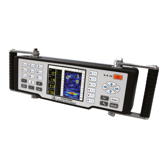
ACOUSTIC А1040 MIRA Low-Frequency Ultrasonic Tomograph CONTROL SYSTEMS 1.3 DESCRIPTION OF THE DEVICE 1.3.1 Design of the device А1040 MIRA tomograph is designed like a single housing unit with removable handles (Figure 1). The device has an integral computer and antenna array. The button “Start”... - Page 10 ACOUSTIC А1040 MIRA Low-Frequency Ultrasonic Tomograph CONTROL SYSTEMS The front panel of the device includes: a big display, a keyboard and two LED indicators (Figure 2). Display Light-emitting diode №2 Light-emitting diode №1 Figure 2 Left keyboard block Right keyboard block When the device is switched on the light-emitting diode No.
- Page 11 ACOUSTIC А1040 MIRA Low-Frequency Ultrasonic Tomograph CONTROL SYSTEMS The measurement unit contains of a matrix antenna array with 48 (12 blocks, each containing 4 elements) low-frequency broad banded transducers of shear waves with dry-point-contact and ceramic wear resistant tips. Hence, they can work with rough surfaces for the long time.
- Page 12 ACOUSTIC А1040 MIRA Low-Frequency Ultrasonic Tomograph CONTROL SYSTEMS As the antenna array consists of dry point contact transducers, the inspection is conducted without any liquid. The interface ensures the use of laser beams which are projected on the surface of the testing object. Thus, the operator can correctly maintain a shift step of the antenna array while performing comprehensive technical diagnostics of the testing object.
- Page 13 ACOUSTIC А1040 MIRA Low-Frequency Ultrasonic Tomograph CONTROL SYSTEMS The internal rechargeable battery provides for 5 hours of the tomograph operation. The increased charge-discharge cycle enhances reliability of the tomograph for long-term applications. Besides, the tomograph can be powered directly from the AC mains.
- Page 14 ACOUSTIC А1040 MIRA Low-Frequency Ultrasonic Tomograph CONTROL SYSTEMS The tomograph allows to transfer data to the external PC for advanced processing by means of a dedicated software. (Figure 6). The inspection is carried out as a step-by-step sounding of the testing object with data combining and volume reconstruc- tion over the whole scanned surface of the testing object.
-
Page 15: Data Processing And Data Reproduction On The Screen
ACOUSTIC А1040 MIRA Low-Frequency Ultrasonic Tomograph CONTROL SYSTEMS 1.3.2 Data processing and data reproduction on the screen The focusing technique of the synthetic aperture with combinational sounding (SAFT-C) is used in the device. The focusing is made in every point of the half-space. The data array is formed by the information received from all antenna measuring pairs of the device. -
Page 16: Display
ACOUSTIC А1040 MIRA Low-Frequency Ultrasonic Tomograph CONTROL SYSTEMS 1.3.3 Display In all operating modes there is an information about time and date and the battery condition in the top information line of the display. At the right the vertical line with icons is located. Their functions vary depending on a device operating mode. Other information represented on the screen depends on the selected mode. -
Page 17: Keyboard
ACOUSTIC А1040 MIRA Low-Frequency Ultrasonic Tomograph CONTROL SYSTEMS 1.3.4 Keyboard The operating keyboard consists of two parts located at the left and at the right of the display. The left part of the keyboard (Figure 10) includes the expanded alphanumeric block. The basic key functions are shown in the Table 2. Table 2 Figure 10 Purpose... - Page 18 ACOUSTIC А1040 MIRA Low-Frequency Ultrasonic Tomograph CONTROL SYSTEMS The right part of the keyboard (Figure 11) includes a key of ON / OFF of the device, six function keys, navigation keys and switching between operating modes keys. The basic key functions are shown in the Table 3. Table 3 Purpose Figure 11...
-
Page 19: Systems And Condition Indication
ACOUSTIC А1040 MIRA Low-Frequency Ultrasonic Tomograph CONTROL SYSTEMS 1.3.5 Systems and condition indication For your convenience the trigger button is located on the handle. By pressing this button, the signal transmission and reception starts. By pressing the trigger button, the field for data collection appears. NOTE: TO OBTAIN CORRECT RESULTS OF INSPECTION DO NOT MOVE THE DEVICE AND WEAKEN THE CLAMPING DURING THE DATA COLLECTION PROCESS! Figure 12... - Page 20 ACOUSTIC А1040 MIRA Low-Frequency Ultrasonic Tomograph CONTROL SYSTEMS MAP MODE This mode is used for the generation of the data arrays in form of B-Scans (perpendicular to the surface) when scanning with the antenna array along the marked lines with a constant step. Any B-Scan from the collected three-dimensional data set can be shown on the screen.
-
Page 21: Software
ACOUSTIC А1040 MIRA Low-Frequency Ultrasonic Tomograph CONTROL SYSTEMS SETTING MODE This mode is used to select and set the parameters and operating pattern. There is a possibility to create and save a set of operating patterns under unique names for different testing objects. The required pattern is then selected from the saved list directly on the real object. - Page 22 D Scan any section of testing object, perpendicular to axis Y. NOTE: THE SPECIFIC SOFTWARE IS NOT INCLUDED IN THE DELIVERY KIT OF THE DEVICE The external software for A1040 MIRA with the possibility of forming 3D models of the object can be ordered directly in ACS-Solutions GmbH, Germany.
-
Page 23: The Description Of Operating Modes
ACOUSTIC А1040 MIRA Low-Frequency Ultrasonic Tomograph CONTROL SYSTEMS 1.4 THE DESCRIPTION OF OPERATING MODES 1.4.1 Setting Mode The mode SETTING is used to set and install the device parameters.When starting to work on a new testing object it is always necessary to begin in this mode. -
Page 24: Parameter Editing
ACOUSTIC А1040 MIRA Low-Frequency Ultrasonic Tomograph CONTROL SYSTEMS 1.4.1.1 Parameter editing Access to all parameters in the SETTING mode for editing. The key functions for parameter editing are shown in the Table 5. Table 5 Description Moving up and down the lines to select a parameter Change parameter value Exit the SETTING mode The parameters and their permissible values are given in the Table 6. -
Page 25: Selection Of Gain And Checking Of The Operating Capacity Of The Antenna Array
ACOUSTIC А1040 MIRA Low-Frequency Ultrasonic Tomograph CONTROL SYSTEMS ▼ Table 6 Parameter Value Description Using the measured velocity Select the speed for SAFT formation On / Off On – the measured velocity of S-waves Off – setting speed in the SETTING mode Velocity, m/s from 1500 to 4 000 with Manual velocity setting... -
Page 26: Automatic Sample Testing
ACOUSTIC А1040 MIRA Low-Frequency Ultrasonic Tomograph CONTROL SYSTEMS 1.4.1.3 Automatic sample testing In the delivery kit a test sample is included. The sample is a plastic plate with holes. It is used to perform the functionality test of each block of the antenna array. For automatic testing and checking the functions of the tomograph system please perform the following operations: - Put the sample with its holes up;... - Page 27 - If the tomograph is not ready, the following information will be displayed on the screen (Figure19). In this case it is necessary to contact with service center of the manufacturer by e-mail at info@acs-international.com or by phone: +49 681-9659-2270.
-
Page 28: Viewing Parameters Saved In B Scans
ACOUSTIC А1040 MIRA Low-Frequency Ultrasonic Tomograph CONTROL SYSTEMS The parameters and their permissible values are given in the Table 8. Table 8 Parameter Value Description Firmware version The current firmware version Free memory left, Mb Free memory left Start of memory cleaning procedure by pressing the key Full memory erase Enter WARNING: THE MEMORY WILL BE CLEANED COMPLETELY. -
Page 29: View And Create Maps
ACOUSTIC А1040 MIRA Low-Frequency Ultrasonic Tomograph CONTROL SYSTEMS 1.4.1.5 View and create maps When entering the mode, in the first line the default map is marked, the parameters of the map are shown on the right (Figure 22). For Viewing the parameters of the saved map, please select its name using the keys For viewing the saved B-Scans card on the screen, please select its name in the list and to press the key Figure 21 Figure 22... - Page 30 ACOUSTIC А1040 MIRA Low-Frequency Ultrasonic Tomograph CONTROL SYSTEMS For removing saved B-scan maps, please press the key . It is impossible to clear map list completely, one map in the list cannot be removed. For creating a new map, please select “Create a map …” using the keys (Figure 23), in the right column the parameters described in the section 1.4.
- Page 31 ACOUSTIC А1040 MIRA Low-Frequency Ultrasonic Tomograph CONTROL SYSTEMS After entering changes it is necessary to leave editing by pressing a key (Figure 25). To save the map, please select its name, for this purpose press the key . The window for changing the map name opens (Figure 26).
- Page 32 ACOUSTIC А1040 MIRA Low-Frequency Ultrasonic Tomograph CONTROL SYSTEMS In default it is suggested to save the map under “the default” name with the serial number addition. It is possible to enter any appropriate name for any map (Figure 27). To save the generated name, please press the key .
- Page 33 ACOUSTIC А1040 MIRA Low-Frequency Ultrasonic Tomograph CONTROL SYSTEMS The functions of the keys during the name editing are shown in the Table 9. Table 9 Description Moving on the keyboard field located on the screen Cursor moving in the name field the left / to the right Entering a letter in the field /performing the action allocated to the key on the screen Entering symbols in the name field using the keyboard Removing a symbol in front of the cursor in the name field...
-
Page 34: Review Mode
ACOUSTIC А1040 MIRA Low-Frequency Ultrasonic Tomograph CONTROL SYSTEMS Functions of icons in the SETTING mode when editing the name are shown in the Table 10. Icon Description Adjustment of parameters Select gain and check the working capacity of the antenna array System options of the device Absence of the B Scans saved / Review of B-Scans parameters saved in memory of the device... - Page 35 ACOUSTIC А1040 MIRA Low-Frequency Ultrasonic Tomograph CONTROL SYSTEMS On the screen the included A-scan is displayed, see Figure 29. The functions of the keys in the REVIEW mode are given in the Table 11. The functions of the icons in the REVIEW mode are given in the Table 12.
-
Page 36: Map Mode
ACOUSTIC А1040 MIRA Low-Frequency Ultrasonic Tomograph CONTROL SYSTEMS 1.4.3 MAP mode The mode is used to collect automatically save the data on the tested object, together with current settings of the system. The indication of B-Scans images generated with the received data is also possible. Make sure that the B-Scans collected in the REVIEW mode are correct, after that you may use the MAP mode. - Page 37 ACOUSTIC А1040 MIRA Low-Frequency Ultrasonic Tomograph CONTROL SYSTEMS After switching on the mode, the screen window with graphic results from the MAP mode opens, it is similar to the window in the REVIEW mode where the images of B-Scans and the mode of MAP control panel are shown (Figure 30). The functions of the keys in the MAP mode are shown in the Table 13.
-
Page 38: Viewing The Saved Data
ACOUSTIC А1040 MIRA Low-Frequency Ultrasonic Tomograph CONTROL SYSTEMS 1.4.4 Viewing the saved data For viewing the saved data, please to press a key in the REVIEW or the MAP mode corresponding to the icon The screen B-scans saved in the REVIEW mode are shown in the Figure 31. The functions of the keys for viewing the saved B-scans are shown in the Table 15. - Page 39 ACOUSTIC А1040 MIRA Low-Frequency Ultrasonic Tomograph CONTROL SYSTEMS The functions of the icons for viewing the saved B-Scans are given in Table 16. Table 16 Icon Description Go to the first saved B-scan Go to the previous saved B-Scan Go to the following saved B-Scan Go to last saved B-Scan Remove the current B-Scan Exit viewing the saved B Scans...
-
Page 40: Proper Use
ACOUSTIC А1040 MIRA Low-Frequency Ultrasonic Tomograph CONTROL SYSTEMS 2.1 OPERATING RESTRICTIONS The device is intended for operating conditions listed in the Section 1. 1 .2 2.2 PREPARING FOR OPERATION 2.2.1 Possible use of the tomograph There are two possibilities of inspection of objects using the tomograph: local and continuous testing. 2.2.1.1 Local testing When performing the local testing mode, the device is placed in any place on the surface of the inspected object. -
Page 41: Preparation Of The Surface Of The Tested Object
ACOUSTIC А1040 MIRA Low-Frequency Ultrasonic Tomograph CONTROL SYSTEMS 2.2.2.1 Preparation of the surface of the tested object To prepare the surface of the tested object, please clean the areas, where the device will be installed, remove all dust and sand and the materials disturbing to penetration of low-frequency ultrasonic waves. Any layers other than concrete, such as polymeric or waterproofing materials or a thick paint coating on physical properties can negatively influence the work of the tomograph. -
Page 42: Performing The Testing
ACOUSTIC А1040 MIRA Low-Frequency Ultrasonic Tomograph CONTROL SYSTEMS 2.2.3 Performing the testing 2.2.3.1 Performing the local testing To perform the local testing, please use the REVIEW mode. Please place the device in proper areas of the inspected surface and press the trigger button. Further it is necessary to study the received image of the section and to draw a conclusion, whether the received data is enough for decision-making or where it is necessary to remove the device for more detailed information. -
Page 43: Technical Maintenance
In case the device does not operate correctly, their es not image or signals, error messages on the screen or after a long downtime and other events it is necessary to switch off and then switch on the device. If it does not help, please contact the service center of the manufacturer by e-mail: info@acs-international.com or phone: +49 681-9659-2270. 3.2.2 Possible malfunctions In the table 17 the malfunctions are shown that can be solved by the operator. -
Page 44: Storage
ACOUSTIC А1040 MIRA Low-Frequency Ultrasonic Tomograph CONTROL SYSTEMS Please store the device in the transport suitcase in a dry room according to generally accepted storage conditions. The storage room shall be free from the current-conducting dust, mixtures of aggressive gases and corrosive vapors able to lead to corrosion and destroying its isolation. -
Page 45: Transportation
ACOUSTIC А1040 MIRA Low-Frequency Ultrasonic Tomograph CONTROL SYSTEMS The device in the transportation suitcase with all accessories can be transported by the railway, motor transport and in heated plane compartments according to generally accepted transportation conditions. During the transportation please make sure to protect the device against the atmospheric precipitation and blows. Arrange- ments should be made to provide steady position of the device during transportation. - Page 46 ACOUSTIC А1040 MIRA Low-Frequency Ultrasonic Tomograph CONTROL SYSTEMS NOTES Operation Manual...
- Page 47 ACOUSTIC А1040 MIRA Low-Frequency Ultrasonic Tomograph CONTROL SYSTEMS Operation Manual...
- Page 48 ACOUSTIC А1040 MIRA Low-Frequency Ultrasonic Tomograph CONTROL SYSTEMS А1040 MIRA Low-Frequency Ultrasonic Tomograph OPERATION MANUAL Revision: February 2018 Operation Manual...
Need help?
Do you have a question about the A1040 MIRA and is the answer not in the manual?
Questions and answers