Table of Contents
Advertisement
Quick Links
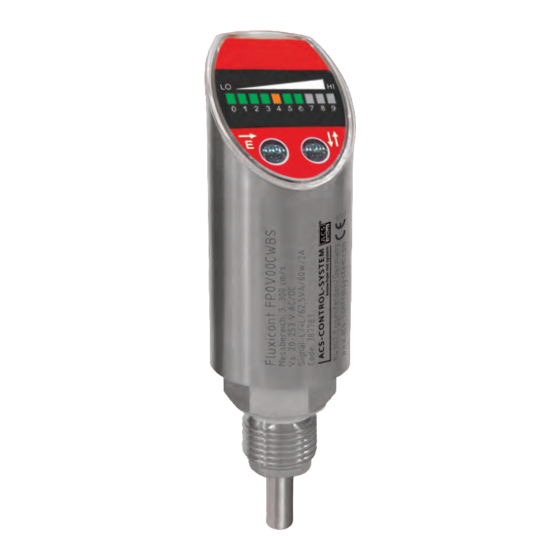
Fluxicont FP
Flow monitor
Monitoring of flows
in liquids
Short manual
03.14
Main features
For flow velocities from 3 to 300 cm/s
Process temperature range from – 30 °C to +110 °C
Process pressure range from –1 bar to 100 bar
Integrated evaluation electronic
Direct voltage with PNP switch output
•
Universal voltage with relay output
•
LED bar graph for flow indication
Enclosure rotatable for optimal operability in each
installation position
Hygienic optimized design with closed operation surface
Advertisement
Table of Contents

Subscribe to Our Youtube Channel
Related Manuals for ACS Fluxicont FP


Summary of Contents for ACS Fluxicont FP
- Page 1 Fluxicont FP Flow monitor Monitoring of flows in liquids Short manual 03.14 Main features For flow velocities from 3 to 300 cm/s Process temperature range from – 30 °C to +110 °C Process pressure range from –1 bar to 100 bar...
- Page 2 You have purchased a high-grade and modern measuring device of ACS-CONTROL-SYSTEM GmbH. We want to give thanks for your purchase and for your confidence to us. The actual technical manual includes instructions for installation, electrical connection and inauguration, as well as the technical data of the device.
-
Page 3: Table Of Contents
Order Code . . . . . . . . . . . . . . . . . . . . . . . . . . . . . . . . . . . . . . . . . . . . . . . . . . . . . . . 13 ACS-CONTROL-SYSTEM GmbH l Lauterbachstr. 57 l D-84307 Eggenfelden l www.acs-controlsystem.de l info@acs-controlsystem.de... -
Page 4: Application
The measuring value is diagrammed at the LED bar graph. By 2 sensor keys and the ten-digit LED bargraph the adjustment to the application specific conditions and the settings for the switch output can be carried out. ACS-CONTROL-SYSTEM GmbH l Lauterbachstr. 57 l D-84307 Eggenfelden l www.acs-controlsystem.de l info@acs-controlsystem.de... -
Page 5: Safety Notes
Using the device in a manner that does not fall within the scope of its intended use, disregarding this instruction, using under-qualified personnel, or making unauthorized alterations releases the manufacturer from liability for any resulting damage. This renders the manufacturer‘s warranty null and void. ACS-CONTROL-SYSTEM GmbH l Lauterbachstr. 57 l D-84307 Eggenfelden l www.acs-controlsystem.de l info@acs-controlsystem.de... -
Page 6: Installation
The sensor tip should be completely surrounded by medium. Position the sensor tip in the area of maximum fluid velocity (pipe center). The minimum sensor immersion length is L ≥16 mm. ACS-CONTROL-SYSTEM GmbH l Lauterbachstr. 57 l D-84307 Eggenfelden l www.acs-controlsystem.de l info@acs-controlsystem.de... - Page 7 Installation from below for horizontal pipes only if the pipe is free of deposits. • Installation from above for horizontal pipes only if the pipe is completely filled with medium. • ACS-CONTROL-SYSTEM GmbH l Lauterbachstr. 57 l D-84307 Eggenfelden l www.acs-controlsystem.de l info@acs-controlsystem.de...
- Page 8 For this reason, steadying sections must be provided in the pipe after a pump, pipe bend, internal fittings and cross-sectional changes. Ø >> Pipe diameter S >> Disturbance influence ACS-CONTROL-SYSTEM GmbH l Lauterbachstr. 57 l D-84307 Eggenfelden l www.acs-controlsystem.de l info@acs-controlsystem.de...
-
Page 9: Electrical Connection
A fuse is integrated internally at the power supply circuit. Due to this the installation of a fine protection is not necessary. The switch output is not protected by this fuse. ACS-CONTROL-SYSTEM GmbH l Lauterbachstr. 57 l D-84307 Eggenfelden l www.acs-controlsystem.de l info@acs-controlsystem.de... -
Page 10: Switch Output
In the case of failure or at wire break the terminal NO is potential-free and the terminal NC is connected to the terminal L/+L. By using a two-channel evaluation, besides the flow monitoring also a function dependent monitoring of the sensor can be realized. ACS-CONTROL-SYSTEM GmbH l Lauterbachstr. 57 l D-84307 Eggenfelden l www.acs-controlsystem.de l info@acs-controlsystem.de... -
Page 11: Connection Scheme
Conductor color standard connection cable M12: BN = brown, WH = white, BU = blue, BK = black The connection cable in not enclosed in the delivery contents. ACS-CONTROL-SYSTEM GmbH l Lauterbachstr. 57 l D-84307 Eggenfelden l www.acs-controlsystem.de l info@acs-controlsystem.de... -
Page 12: Maintenance
A returning must be refrained, if it is not possible by 100% to remove the unhealthily product • completely, because e.g. it is penetrate into cracks or is diffused through plastic. ACS-CONTROL-SYSTEM GmbH l Lauterbachstr. 57 l D-84307 Eggenfelden l www.acs-controlsystem.de l info@acs-controlsystem.de... -
Page 13: Order Code
, PNP switch output WB Universal voltage 20…253V , relay output AC/DC Electrical connection Plug M12 Fluxicont Installation material and connection cable are not enclosed in contents of delivery . ACS-CONTROL-SYSTEM GmbH l Lauterbachstr. 57 l D-84307 Eggenfelden l www.acs-controlsystem.de l info@acs-controlsystem.de...
Need help?
Do you have a question about the Fluxicont FP and is the answer not in the manual?
Questions and answers