Danfoss VLT AutomationDrive FC 361 Operating Manual
90–315 kw, enclosure size j8–j9
Hide thumbs
Also See for VLT AutomationDrive FC 361:
- Programming manual (196 pages) ,
- Design manual (102 pages) ,
- Service manual (370 pages)
Table of Contents
Advertisement
Quick Links
Download this manual
See also:
Programming Manual
Advertisement
Table of Contents
Troubleshooting

Subscribe to Our Youtube Channel
Related Manuals for Danfoss VLT AutomationDrive FC 361


Summary of Contents for Danfoss VLT AutomationDrive FC 361
- Page 1 ENGINEERING TOMORROW Operating Guide VLT® AutomationDrive FC 361 90–315 kW, Enclosure Size J8–J9 vlt-drives.danfoss.com...
-
Page 3: Table Of Contents
5.1 Safety Instructions 5.2 EMC-compliant Installation 5.3 Wiring Schematic 5.4 Connecting to Ground 5.5 Connecting the Motor 5.6 Connecting the AC Mains 5.7 Terminal Dimensions 5.8 Control Wiring 6 Pre-start Check List MG06I102 Danfoss A/S © 06/2018 All rights reserved. - Page 4 10.5 Cable Specifications 10.6 Control Input/Output and Control Data 10.7 Fuses and Circuit Breakers 10.8 Fastener Tightening Torques 10.9 Enclosure Dimensions 11 Appendix 11.1 Abbreviations and Conventions 11.2 Parameter Menu Structure Index Danfoss A/S © 06/2018 All rights reserved. MG06I102...
-
Page 5: Introduction
Table 1.1 shows the version of the manual and the corresponding software version. Manual version Remarks Software version MG06I1xx First edition. 1.0x Table 1.1 Manual and Software Version MG06I102 Danfoss A/S © 06/2018 All rights reserved. -
Page 6: Safety
Leakage currents exceed 3.5 mA. Failure to ground the frequency converter properly can result in death or serious injury. • Ensure the correct grounding of the equipment by a certified electrical installer. Danfoss A/S © 06/2018 All rights reserved. MG06I102... - Page 7 • Exterior areas marked by the high-temperature symbol (yellow triangle) are hot while the drive is in use and immediately after being powered off. MG06I102 Danfoss A/S © 06/2018 All rights reserved.
-
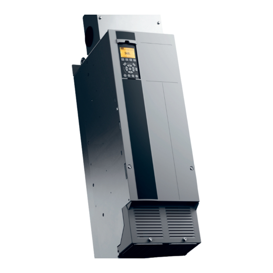
Page 8: Product Overview
Drive dimensions [mm (in)] Width 250.0 (9.8) 350.0 (13.8) Depth 375.0 (14.8) 375.0 (14.8) Maximum weight [kg (lb)] 101.2 (223.1) 168.6 (376.1) Table 3.1 Power Ratings, Weight, and Dimensions, Enclosure Sizes J8–J9, 380–480 V Danfoss A/S © 06/2018 All rights reserved. MG06I102... -
Page 9: Interior View Of J8 Drive
Motor output terminals 96 (U), 97 (V), 98 (W) Mains input terminals 91 (L1), 92 (L2), 93 (L3) Cable clamps Lifting ring 10 Ground terminals Illustration 3.1 Interior View of J8 Drive MG06I102 Danfoss A/S © 06/2018 All rights reserved. -
Page 10: Interior View Of J9 Drive
Relays 1 and 2 Control terminals Motor output terminals 96 (U), 97 (V), 98 (W) Mains input terminals 91 (L1), 92 (L2), 93 (L3) 10 Ground terminals Illustration 3.2 Interior View of J9 Drive Danfoss A/S © 06/2018 All rights reserved. MG06I102... -
Page 11: View Of Control Shelf
Analog I/O connector Digital I/O and 24 V supply Relay 1 (01, 02, 03) on power card Lifting rings Relay 2 (04, 05, 06) on power card Illustration 3.3 View of Control Shelf MG06I102 Danfoss A/S © 06/2018 All rights reserved. -
Page 12: Local Control Panel (Lcp)
Motor current [A] A1.3 Parameter 0-22 Display Line 1.3 Small Power [kW] Parameter 0-23 Display Line 2 Large Frequency [Hz] Parameter 0-24 Display Line 3 Large kWh counter Table 3.2 LCP Display Area Danfoss A/S © 06/2018 All rights reserved. MG06I102... - Page 13 ▲ ▼ ◄ ► Moves between items in the menu. Reset Resets the drive manually after a fault has been cleared. Table 3.4 LCP Navigation Keys Table 3.6 LCP Operation Keys and Reset MG06I102 Danfoss A/S © 06/2018 All rights reserved.
-
Page 14: Lcp Menus
Select Q5 Changes Made for information about: cards added to the unit enable extra parameters associated • The 10 most recent changes. with the option device. • Changes made from default setting. Danfoss A/S © 06/2018 All rights reserved. MG06I102... -
Page 15: Mechanical Installation
Voltage [V] Altitude restrictions 380–480 At altitudes above 3000 m (9842 ft), contact Danfoss regarding PELV. Table 4.1 Installation at High Altitudes MG06I102 Danfoss A/S © 06/2018 All rights reserved. -
Page 16: Installation And Cooling Requirements
9 Maintenance, Diagnostics, and Troubleshooting. Cooling fans Fans provide airflow to cool the drive. When fans are exposed to dusty environments, the dust can damage the fan bearings and cause premature fan failure. Also, dust Danfoss A/S © 06/2018 All rights reserved. MG06I102... -
Page 17: Lifting The Drive
102 m /hr (60 CFM) 420 m /hr (250 CFM) glasses, and safety shoes. 204 m /hr (120 CFM) 840 m /hr (500 CFM) Table 4.2 Airflow ° Illustration 4.2 Lifting the Drive MG06I102 Danfoss A/S © 06/2018 All rights reserved. -
Page 18: Mounting The Drive
2 M10 bolts in the mounting holes. Plastic tabs Tabs removed for cable access Illustration 4.4 Cable Openings in Plastic Gland Plate Top mounting holes Lower fastener slots Illustration 4.3 Drive-to-wall Mounting Holes Danfoss A/S © 06/2018 All rights reserved. MG06I102... -
Page 19: Electrical Installation
If shielded cables or metal conduits are not used, the unit and the installation do not meet regulatory limits See chapter 10.5 Cable Specifications for recommended wire on radio frequency (RF) emission levels. sizes and types. MG06I102 Danfoss A/S © 06/2018 All rights reserved. - Page 20 For installations above 2000 m (6500 ft) altitude, contact Danfoss regarding PELV compliance. NOTICE PELV COMPLIANCE Prevent electric shock by using protective extra low voltage (PELV) electrical supply and complying with local and national PELV regulations. Danfoss A/S © 06/2018 All rights reserved. MG06I102...
- Page 21 Mains supply Brake resistor Bare (unpainted) surface Metal box Star washers Connection to motor Brake cable (shielded) Motor Motor cable (shielded) EMC cable gland Illustration 5.1 Example of Proper EMC Installation MG06I102 Danfoss A/S © 06/2018 All rights reserved.
-
Page 22: Wiring Schematic
32 (D IN) (N RS485) 69 0 V (PNP) 24 V (NPN) (COM RS485) 61 33 (D IN) 0 V (PNP) (PNP) = Source (NPN) = Sink Illustration 5.2 Basic Wiring Schematic Danfoss A/S © 06/2018 All rights reserved. MG06I102... -
Page 23: Connecting To Ground
There is a risk of burst transient when the ground potential between the drive and the control system is different. Install equalizing cables between the system components. Recommended cable cross-section: 16 mm (5 AWG). MG06I102 Danfoss A/S © 06/2018 All rights reserved. - Page 24 Electrical Installation VLT® AutomationDrive FC 361 Illustration 5.3 Ground Terminals (J8 shown) Danfoss A/S © 06/2018 All rights reserved. MG06I102...
-
Page 25: Connecting The Motor
Connect the 3-phase motor wiring to terminals 96 (U), 97 (V), and 98 (W), see Illustration 5.4. Tighten the terminals in accordance with the information provided in chapter 10.8 Fastener Tightening Torques. MG06I102 Danfoss A/S © 06/2018 All rights reserved. - Page 26 Electrical Installation VLT® AutomationDrive FC 361 Illustration 5.4 Motor Terminals (J8 shown) Danfoss A/S © 06/2018 All rights reserved. MG06I102...
-
Page 27: Connecting The Ac Mains
(grounded delta), ensure that parameter 14-50 RFI Filter is set to [0] Off to avoid damage to the DC link and to reduce ground capacity currents. Tighten the terminals in accordance with the information provided in chapter 10.8 Fastener Tightening Torques. MG06I102 Danfoss A/S © 06/2018 All rights reserved. - Page 28 Electrical Installation VLT® AutomationDrive FC 361 Illustration 5.5 AC Mains Terminals (J8 shown). For a detailed view of terminals, see chapter 5.7 Terminal Dimensions. Danfoss A/S © 06/2018 All rights reserved. MG06I102...
-
Page 29: Terminal Dimensions
Electrical Installation Operating Guide 5.7 Terminal Dimensions 5.7.1 J8 Terminal Dimensions 188 (7.4) 83 (3.3) Mains terminals Ground terminals Motor terminals Illustration 5.6 J8 Terminal Dimensions (Front View) MG06I102 Danfoss A/S © 06/2018 All rights reserved. - Page 30 VLT® AutomationDrive FC 361 10 (0.4) 3X M8x18 13 (0.5) 32 (1.3) 13 (0.5) 32 (1.3) 1 and 4 Mains terminals 2 and 5 Motor terminals Ground terminals Illustration 5.7 J8 Terminal Dimensions (Side Views) Danfoss A/S © 06/2018 All rights reserved. MG06I102...
- Page 31 Electrical Installation Operating Guide 5.7.2 J9 Terminal Dimensions 319 (12.6) 200 (7.9) Mains terminals Ground terminals Motor terminals Illustration 5.8 J9 Terminal Dimensions (Front View) MG06I102 Danfoss A/S © 06/2018 All rights reserved.
- Page 32 22 (0.9) 15 (0.6) 18 (0.7) 35 (1.4) 19 (0.8) 38 (1.5) 1 and 4 Mains terminals 2 and 5 Motor terminals Ground terminals Ground terminals Illustration 5.9 J9 Terminal Dimensions (Side Views) Danfoss A/S © 06/2018 All rights reserved. MG06I102...
-
Page 33: Control Wiring
12, 13 – +24 V DC 24 V DC supply voltage for digital inputs and external transducers. Maximum output Illustration 5.10 Control Terminal Locations current 200 mA for all 24 V loads. MG06I102 Danfoss A/S © 06/2018 All rights reserved. - Page 34 Analog Input 1 Switches A53 and A54 select mA or V. Parameter Feedback group 6-2* Analog Input 2 – – Common for analog input. Table 5.3 Analog Input/Output Terminal Descriptions Danfoss A/S © 06/2018 All rights reserved. MG06I102...
- Page 35 27, do not remove that wiring. NOTICE The drive cannot operate without a signal on terminal 27, unless terminal 27 is reprogrammed using parameter 5-12 Terminal 27 Digital Input. MG06I102 Danfoss A/S © 06/2018 All rights reserved.
- Page 36 The analog input terminals 53 and 54 allow setting of network topology, and it contains the following features: input signal to voltage (0–10 V) or current (0/4–20 mA). • Either Danfoss FC or Modbus RTU communication protocol, which are internal to the drive, can be Default parameter setting: •...
-
Page 37: Pre-Start Check List
Ensure that the unit is mounted on an unpainted, metal surface. • Vibration Check that the unit is mounted solidly, or that shock mounts are used, if necessary. • Check for an unusual amount of vibration. Table 6.1 Pre-start Check List MG06I102 Danfoss A/S © 06/2018 All rights reserved. -
Page 38: Commissioning
ON position to apply power to the • drive. Press [Back] twice to show the status view. • Press [Main Menu] once to go back to the main menu. Danfoss A/S © 06/2018 All rights reserved. MG06I102... - Page 39 (AMA) and press [OK]. Table 7.2 Quick Set-up Settings Select [1] Enable complete AMA and press [OK]. Press [Hand On] and then [OK]. The test runs automatically and indicates when it is complete. MG06I102 Danfoss A/S © 06/2018 All rights reserved.
-
Page 40: Testing Before System Start-Up
Press [►] for positive speed reference (parameter 1-06 Clockwise Direction at [0] Normal). In parameter 16-57 Feedback [RPM], check that the feedback is positive. For more information on the encoder option, refer to the option manual. Danfoss A/S © 06/2018 All rights reserved. MG06I102... -
Page 41: Parameter Setting
Loss of programming, motor data, localization, and monitoring records occurs when restoring default settings. To create a back-up, upload data to the LCP before initialization. Refer to chapter 7.5.1 Uploading and Downloading Parameter Settings. MG06I102 Danfoss A/S © 06/2018 All rights reserved. -
Page 42: Wiring Configuration Examples
= 1500 RPM speed. = 0 Hz speed and 10 V DC input = 50 Hz speed. Table 8.3 Speed Reference (Using a Manual Potentiometer) Table 8.1 Analog Speed Reference (Voltage) Danfoss A/S © 06/2018 All rights reserved. MG06I102... -
Page 43: Wiring For Start/Stop
Digital Input is set to [0] No Latched Start (18) operation, a jumper wire to Stop Inverse (27) terminal 27 is not needed. Illustration 8.3 Latched Start/Stop Inverse Table 8.5 Start/Stop Command MG06I102 Danfoss A/S © 06/2018 All rights reserved. -
Page 44: Wiring For External Alarm Reset
Digital Input D IN * = Default value D IN Notes/comments: D IN D IN D IN D IN +10 V A IN A IN A OUT Table 8.8 External Alarm Reset Danfoss A/S © 06/2018 All rights reserved. MG06I102... -
Page 45: Maintenance, Diagnostics, And Troubleshooting
Replace the panel and secure it to the back of sink and allows the heat sink to be cleaned of any dust the enclosure with the screws previously buildup. removed. Tighten the fasteners according to chapter 10.8 Fastener Tightening Torques. MG06I102 Danfoss A/S © 06/2018 All rights reserved. -
Page 46: Status Messages
4-56 Warning • External signals. Feedback Low. • Serial communication. • Internal preset references. Local The drive uses reference values from the LCP. Table 9.2 Reference Site Danfoss A/S © 06/2018 All rights reserved. MG06I102... - Page 47 Start delay In parameter 1-71 Start Delay, a delay starting time was set. A start command is activated and the motor starts after the start delay time expires. MG06I102 Danfoss A/S © 06/2018 All rights reserved.
-
Page 48: Warning And Alarm Types
Warning indicator light Alarm indicator light • Digital reset input command. Warning • Serial communication reset input command. Alarm On (flashing) • Trip lock On (flashing) Auto reset. Illustration 9.4 Status Indicator Lights Danfoss A/S © 06/2018 All rights reserved. MG06I102... -
Page 49: List Of Warnings And Alarms
The drive trips when the counter reaches 100% if warning limit. The limit depends on the drive voltage parameter 1-90 Motor Thermal Protection is set to rating. The unit is still active. trip options. MG06I102 Danfoss A/S © 06/2018 All rights reserved. - Page 50 • Parameter 15-60 Option Mounted. operate safely at a higher torque. • Parameter 15-61 Option SW Version (for each • Check the application for excessive current draw option slot). on the motor. Danfoss A/S © 06/2018 All rights reserved. MG06I102...
- Page 51 If the fan is commanded to run and there is no missing. feedback from the sensor, this alarm appears. For drives with AC fans, the voltage to the fan is monitored. MG06I102 Danfoss A/S © 06/2018 All rights reserved.
- Page 52 Check for loose or missing wiring. ALARM 32, Motor phase W missing It may be necessary to contact the Danfoss supplier or Motor phase W between the drive and the motor is service department. Note the code number for further missing.
- Page 53 Troubleshooting 5124 Option in slot B: Hardware incompatible with the • Contact the Danfoss supplier or Danfoss Service control board hardware. Department. 5125 Option in slot C0: Hardware incompatible with the WARNING 48, 1.8 V supply low control board hardware.
- Page 54 The control card and power card are incompatible. To • Set the tolerable feedback loss time in check compatibility, contact the Danfoss supplier with the parameter 4-32 Motor Feedback Loss Timeout. type code from the unit nameplate and the part numbers WARNING 62, Output frequency at maximum limit of the cards.
- Page 55 The mixing-fan fault can be configured as a 2 = Right inverter module. warning or an alarm trip in parameter 14-53 Fan Monitor. 2 = Second drive from the left inverter module. 3 = Right inverter module. MG06I102 Danfoss A/S © 06/2018 All rights reserved.
-
Page 56: Troubleshooting
Check the wiring for fault within the AC drive. terminal blocks. shorts or incorrect connections. If the display continues to cut out, follow the procedure for Display dark/No function. Danfoss A/S © 06/2018 All rights reserved. MG06I102... - Page 57 Possible incorrect settings in Check brake parameters. Check ramp time Check parameter groups 2-0* DC Brake and not brake the brake parameters. Ramp- settings. 3-0* Reference Limits. down times may be too short. MG06I102 Danfoss A/S © 06/2018 All rights reserved.
- Page 58 9.5 List of Warnings and Alarms. parameter 3-42 Ramp 1 Ramp Down Time. problems Check that motor data are entered correctly. Enable overvoltage control in parameter 2-17 Over-voltage Control. Table 9.5 Troubleshooting Danfoss A/S © 06/2018 All rights reserved. MG06I102...
-
Page 59: Specifications
If the switching frequency is higher than the default setting, the power losses can increase. LCP and typical control card power consumptions are included. For power loss data according to EN 50598-2, refer to drives.danfoss.com/knowledge-center/energy- efficiency-directive/#/. Options and customer load can add up to 30 W to the losses, though usually a fully loaded control card and options for slots A and B each add only 4 W. -
Page 60: Mains Supply
If the switching frequency is higher than the default setting, the power losses can increase. LCP and typical control card power consumptions are included. For power loss data according to EN 50598-2, refer to drives.danfoss.com/knowledge-center/energy- efficiency-directive/#/. Options and customer load can add up to 30 W to the losses, though usually a fully loaded control card and options for slots A and B each add only 4 W. -
Page 61: Motor Output And Motor Data
EMC standards, Immunity EN 61800-3 Energy efficiency class 1) Determined according to EN 50598-2 at: • Rated load. • 90% rated frequency. • Switching frequency factory setting. • Switching pattern factory setting. MG06I102 Danfoss A/S © 06/2018 All rights reserved. -
Page 62: Cable Specifications
10 bit (+ sign) Accuracy of analog inputs Maximum error 0.5% of full scale Bandwidth 100 Hz The analog inputs are galvanically isolated from the supply voltage (PELV) and other high-voltage terminals. Danfoss A/S © 06/2018 All rights reserved. MG06I102... - Page 63 Resolution of frequency outputs 12 bit 1) Terminals 27 and 29 can also be programmed as inputs. The digital output is galvanically isolated from the supply voltage (PELV) and other high-voltage terminals. MG06I102 Danfoss A/S © 06/2018 All rights reserved.
- Page 64 1:100 of synchronous speed 30–4000 RPM: Maximum error of ±8 RPM Speed accuracy (open loop) All control characteristics are based on a 4-pole asynchronous motor. Control card performance Scan interval 5 M/S Danfoss A/S © 06/2018 All rights reserved. MG06I102...
-
Page 65: Fuses And Circuit Breakers
Class L fuse. The input voltage and power rating is found on the product nameplate. For more information regarding the nameplate, see chapter 4 Mechanical Installation. MG06I102 Danfoss A/S © 06/2018 All rights reserved. -
Page 66: Fastener Tightening Torques
19 (168)/37 (335) Ground terminals M8/M10 9.6 (84)/19.1 (169) Load sharing terminals M10/M12 19 (168)/37 (335) Relay terminals – 0.5 (4) Door/panel cover 2.3 (20) Gland plate 2.3 (20) Table 10.6 Fastener Torque Ratings Danfoss A/S © 06/2018 All rights reserved. MG06I102... -
Page 67: Enclosure Dimensions
Specifications Operating Guide 10.9 Enclosure Dimensions 10.9.1 J8 Exterior Dimensions 250 (9.8) 160 (6.3) 61 (2.4) 128 (5.0) 660 (26.0) 495 (19.5) Illustration 10.2 Front View of J8 MG06I102 Danfoss A/S © 06/2018 All rights reserved. - Page 68 Specifications VLT® AutomationDrive FC 361 375 (14.8) 133 (5.2) 157 (6.2) 64 (2.5) 82 (3.2) 18 (0.7) 20 (0.8) 201 (7.9) 148 (5.8) 844 (33.2) Illustration 10.3 Side View of J8 Danfoss A/S © 06/2018 All rights reserved. MG06I102...
- Page 69 25 (1.0) 909 (35.8) 11 (0.4) 77.5 (3.1) 200 (7.9) 889 (35.0) 25 (1.0) 844 (33.2) 11 (0.4) 656 (25.8) 20 (0.8) (0.9) 9 (0.3) 200 (7.9) Illustration 10.4 Back View of J8 MG06I102 Danfoss A/S © 06/2018 All rights reserved.
- Page 70 Specifications VLT® AutomationDrive FC 361 10.9.2 J9 Enclosure Dimensions 350 (13.8) 218 (8.6) 59 (2.3) 176 (6.9) 868 (34.2) 611 (24.1) Illustration 10.5 Front View of J9 Danfoss A/S © 06/2018 All rights reserved. MG06I102...
- Page 71 Specifications Operating Guide 375 (14.8) 203 (8.0) (4.1) 64 (2.5) 142 (5.6) 18 (0.7) 20 (0.8) 246 (9.7) 1050 (41.3) 148 (5.8) Illustration 10.6 Side View for J9 MG06I102 Danfoss A/S © 06/2018 All rights reserved.
- Page 72 25 (1.0) 107 (4.2) 213 (8.4) 1122 (44.2) 320 (12.6) 1096 (43.1) 1051 (41.4) 857 (33.7) (1.6) 11 (0.4) 24 (0.9) 20 (0.8) 9 (0.3) 271 (10.1) Illustration 10.7 Back View for J9 Danfoss A/S © 06/2018 All rights reserved. MG06I102...
-
Page 73: Appendix
All dimensions are in mm (inch). Milliamp 11.2 Parameter Menu Structure Miniature circuit breakers Motor control processor Millivolts NEMA National Electrical Manufacturers Association Negative temperature coefficient Nominal motor power Printed circuit board MG06I102 Danfoss A/S © 06/2018 All rights reserved. - Page 74 Appendix VLT® AutomationDrive FC 361 Danfoss A/S © 06/2018 All rights reserved. MG06I102...
- Page 75 Appendix Operating Guide MG06I102 Danfoss A/S © 06/2018 All rights reserved.
- Page 76 Appendix VLT® AutomationDrive FC 361 Danfoss A/S © 06/2018 All rights reserved. MG06I102...
-
Page 77: Index
Environment................... 59 Control card Exterior dimensions Overtemperature trip point............57 J8......................65 RS485 specifications............... 61 J9......................68 Specifications..................62 Warning....................52 External alarm reset................42 Control input/output Descriptions and default settings..........31 MG06I102 Danfoss A/S © 06/2018 All rights reserved. - Page 78 High voltage..................49, 50 Manual High voltage warning................4 Version number................... 3 Humidity....................14 MCT 10...................... 37 Menu Descriptions of.................. 12 Keys....................... 11 Indicator lights..................46 Input Power....................21 Voltage....................36 Input specifications................60 Danfoss A/S © 06/2018 All rights reserved. MG06I102...
- Page 79 Warning....................52 Disconnect..................63 Programming..................11 Pulse Input specifications................. 61 Temperature................... 14 Terminal dimensions J8......................27 Qualified personnel................4 J9......................29 Quick menu..................11, 12 Terminal torque rating................ 64 Ramp-down time.................. 56 MG06I102 Danfoss A/S © 06/2018 All rights reserved.
- Page 80 Types of....................46 Weight......................6 Windmilling....................5 Wire size....................23 Wiring configurations External alarm reset................ 42 Open loop................... 40 Start/stop.................... 41 Thermistor..................42 Wiring control terminals..............33 Wiring schematic Drive...................... 20 Wiring schematic................20 Danfoss A/S © 06/2018 All rights reserved. MG06I102...
- Page 81 Index Operating Guide MG06I102 Danfoss A/S © 06/2018 All rights reserved.
- Page 82 Danfoss can accept no responsibility for possible errors in catalogues, brochures and other printed material. Danfoss reserves the right to alter its products without notice. This also applies to products already on order provided that such alterations can be made without subsequential changes being necessary in specifications already agreed. All trademarks in this material are property of the respective companies.
Need help?
Do you have a question about the VLT AutomationDrive FC 361 and is the answer not in the manual?
Questions and answers