
Related Manuals for Taiden HCS-5300


Summary of Contents for Taiden HCS-5300
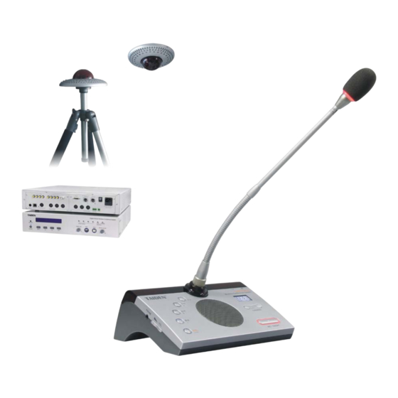
- Page 1 HCS-5300 Digital Infra-red Wireless Conference System Excellent solutions for conferences Conference Management System Software Installation and Operating Manual V 4.2.6...
- Page 2 This product is conform to the rules of the European directive 2004/108/EC ■ If any detailed information needed, please contact your local agent or TAIDEN service center in your region. Any feedback, advice and suggestion about the products is appreciated.
-
Page 3: Table Of Contents
Contents Chapter 1. Installation and Running ............1 1.1 Running Environment................1 1.2 Installation....................1 1.3 Software Running ..................1 Chapter 2. Primary Window ..............2 Chapter 3. File Management ...............3 3.1 Meeting Type ..................3 3.2 Import Delegate Data ................4 3.3 File Transfers .................. - Page 4 Chapter 6. Conference Control ............50 6.1 Hot Backup ................... 50 6.2 Start Meeting ..................50 6.3 End Meeting..................50 6.4 Agenda Control..................51 6.5 Seat Sign-in ..................52 6.6 Microphone Control................53 6.7 Topic and Voting ................... 59 6.8 Video Switch ..................64 6.9 Screen Control..................
-
Page 5: Chapter 1. Installation And Running
Hardware requirements: Pentium 4 2.0G/1G or higher. Software requirements: Windows 2000/XP/Vista/Win7. 1.2 Installation CD Contents The application software of HCS-5300 conference system. Installation guide Double click and run “Install.exe” on this CD. 1.3 Software Running Once installation is completed, a shortcut named “DCS.exe” will appear on Windows desktop. -
Page 6: Chapter 2. Primary Window
Chapter 2. Primary Window According to conference traditions, the primary window of the conference system application File Management, System Setup, Conference Preparation, software consists of separated parts: Conference Control, Report System, and Assistant Functions. The primary window of the conference system software is shown below: Figure: Primary Window of the Conference System File Management: including Meeting Type, Import Delegate Data, File Transfers, Backup/Restore;... -
Page 7: Chapter 3. File Management
Chapter 3. File Management Including Meeting Type, Import Delegate Data, File Transfers, Backup/Restore. 3.1 Meeting Type Figure: Meeting Type Importing Style: Created From Original Database: create an empty database; Created From List Selected Database: create the same type of database according to the selection from the left side list;... -
Page 8: Import Delegate Data
3.2 Import Delegate Data Import delegate information from excel or text file. Delegate information includes: Number, Name, Gender, Team, Group, Company, Department, Title, Clan, Seat, Photo, Presidium, etc. Figure: Import Delegate Data The left side is a delegate type option, including formal delegate, nonvoting delegate, guest, audience, and staff. - Page 9 5. Import: use of this function will delete all existing delegate data and import all new data from excel or text file. 6. Update Import: use of this function will not delete existing delegate data and just import new delegate data or update original delegate data from excel or text file. Note: photo format supported including bmp, jpg, jpeg, gif, png, tif, tiff;...
-
Page 10: File Transfers
3.3 File Transfers Use this function to update automatically data files from the server to the sign-in machine or the backup server. Figure: File Transfers Interface 3.4 Backup and Restore Backup/Restore are used to backup conference data from the database into a folder or to restore conference data from a folder into the database. -
Page 11: Chapter 4. System Setup
Chapter 4. System Setup Including Connect to CMU, Venue Designer, Screen Management, Video Tracking, Simultaneous Interpretation, Short Message, Unit Management, User Management, IP Authorization, System Parameters, CMU Parameters; Figure: System Setup 4.1 Connect to CMU Figure: Connect To CMU Figure: Looking for CMU by Broadcast The system software connects to and communicates with the CMU. -
Page 12: Venue Designer
4.2 Venue Designer Venue designer: the venue designer is the reproduction of the actual layout of the conference venue in the form of a conference venue file (CVF). Its extended filename is .trm. The facilities such as seat arrangement (i.e. both arrange seat and Unit Arrangement), entrance sign-in (access control), seat sign-in, and microphone control shall use the conference venue file to perform normal edition advanced edition... - Page 13 Design conference venue The procedure to create a CVF by the Venue Designer (Common edition) is as follows: Create a new CVF Click “New” button in the toolbar, and the dialog box of meeting room configuration appears as shown in the figure below: Figure: New Meeting Room The background color, room size, and other related parameters (i.e.
- Page 14 Save CVF Don’t forget to save the CVF when the design is completed by clicking the “save” button. If it is the first time you save a new CVF, select the path and the input filename in the pop-up dialog box. Then click “OK”...
-
Page 15: Venue Designer (Advanced Edition)
4.2.2 Venue Designer (Advanced Edition) The initial interface of the venue designer (Advanced edition) is as in figure below: The functional buttons for file operation (bitmap buttons) and object operation (buttons below bitmap buttons) are in the toolbars at the upper side. The functions are also available in the file Object Properties right-click pop-up menu. - Page 16 Paste: paste object(s); Delete: delete selected object(s); Undo: undo previous operation; Redo: redo previous operation. 2. Object properties instruction Object Propertie s dialog box is as figure above, and it contains: Group Name: define the name shown in the object list on the left side; Object Name: select object name for current object group in the combo box;...
- Page 17 The background color, room size, and other meeting room parameters (i.e. background image, line number and number per line, etc.) are also configurable. Click “OK” to create a new CVF, These “Configuration” parameters can be changed later through the menu on the toolbar. Notes: The comparison of the Meeting Room Configuration menus (2) Define object...
- Page 18 Figure: Define Object The functions of these items are: Object Name: specify the name of the object/object group; Image path: specify the directory path of the status images of the object selected. The default path is “Rooms” folder in the main directory path of the application. It is recommended saving these images in the default path (i.e.
- Page 19 If an object is a label or background, only image0 is necessary. Visible characters: if the size of the image is less than 30x30 pixels, no caption will be visible on the image, neither will the delegate name be visible in Seat Arrangement Transparency: if the initialized background color is set to transparent, the transparent area of the object is transparentized;...
- Page 20 Caption: The setup is similar to the "Object ID". Status: Generally, the default value is 0 or 3; it can be set to another if needed. Radian: Arrange the object group in an arc form according to the specified value. Transparent: If checked, the transparent area is shown transparently;...
- Page 21 (7) Adjust object layer Object layer is related to the order it is added by default. User can adjust the layer by using “ ” and ” ” button under the object list on the primary window of the Venue designer. (8) Save CVF “Save”...
-
Page 22: Screen Management
4.3 Screen Management Screen management is to design each screen and their related activating event. Figure: Screen Management 4.3.1 Screen Project Setup Different pre-defined screen projects for different languages. a) Select Screen Project: select screen project to edit and display; b) New, Rename, Delete: create, rename or delete a screen project;... -
Page 23: Predefined
4.3.2 Predefined Pages Predefined Pages: define the display effects of screen. Operation of predefined pages: “Page Color” , select the color which you Page Color: click the color pane at the right side of need from the color palette; “Page Name “Page Size”... -
Page 24: Screen Event
Picture: add a picture object to the page; Panel: add a panel object to the page; Bevel: add a bevel object to the page; Shape: add a shape object to the page; Dynamic Text: add a dynamic text object to the page, dynamic text is a variable, such as voting result, sign-in result, etc.;... -
Page 25: Alias
4.3.4 Alias Give each screen an alias for convenience. Figure: Screen alias editor interface “Modify” Modify: select a screen in the list, and input screen alias, click button; Visible: select this item, the screen content will be displayed immediately once the meeting started. -
Page 26: Video Tracking
4.4 Video Tracking Video Matrix Predefine Position Panorama The Video tracking system includes three sub modules: Control . This facility needs hardware support (HCS-4311M/TMX0804 Video Switch Unit). 4.4.1 Video Matrix Setup video matrix, there are two kinds of video matrix: HCS-4311M and TMX0804. User shall choose the correct model according to the actual connection. -
Page 27: Predefine Position
TMX0804 matrix setup: Open video matrix interface and choose TMX0804 matrix, as in the figure below: Figure: TMX0804 Video Matrix interface TMX0804 is a high definition video matrix, including one 8x4 video matrix and one 8x1 audio matrix. The video input equipment includes dome camera, fixed camera, computer and another video input device. - Page 28 The camera control interface is shown in the figure below: Figure: Camera control interface Select Camera 4. Select the proper camera in the combo box (since each conference can be equipped with multiple cameras, the operator shall select the proper camera to give the best image of each participator);...
-
Page 29: Panorama Control
c. “Auto Iris” is applied for all predefined positions. If “Auto Iris” option is checked, then all predefined positions will use auto iris; if not checked, the iris for each predefined position can be adjusted and saved respectively. 4.4.3 Panorama Control Preset the panorama of the conference venue, as in the figure below: Figure: Panorama control interface Operation: select proper camera and predefine position number, then adjust the camera angle by... -
Page 30: Simultaneous Interpretation (S. I.)
4.5 Simultaneous Interpretation (S. I.) Simultaneous interpretation system in conference preparation includes two sub modules: Simultaneous Interpretation Channel Setup and Booth Setup. 4.5.1 Simultaneous Interpretation Channel Setup Setup of simultaneous interpretation channel, as in figure below: Figure: S.I. Channel Setup Select SI Interface: select SI interface (Interp. -
Page 31: Booth Setup
4.5.2 Booth Setup When we select the Interp. Units as SI interface, set the outgoing languages for the A, B, C channels of each interpretation booth. The system supports 3 interpretation booths. Each booth should set the outgoing A channel, and whether outgoing B and C channel is needed. -
Page 32: Short Message
4.6 Short Message Figure: Short Message Short Message List: existing short messages; Edit: edit short message; Preview: preview short message; Font: set up short message font and format; Control: create, save and delete short message; Send: send short message to all interpreter units. -
Page 33: Unit Management
4.7 Unit Management Unit Setup Unit Arrangement Unit Management in conference preparation includes 4.7.1 Unit Setup This module is to set up facilities for each conference contribution unit. The facilities include different Parameters (Gain, Bass, and Treble). Figure: Setup contribution unit interface On the left side all contribution units are listed individually, on the right side the available facilities are displayed, including unit function, append contribution units (append, delete, delete all), authorize (start, stop), setup unit (Gain, Bass, Treble). -
Page 34: Unit Arrangement
Setup CU: select contribution unit(s) (One infrared unit or All infrared units), set up parameters (Gain, Base, Treble) of the selected unit(s), then click the “Setup CU” button. If read units’ status failed, the following interface is shown: Figure: Get infrared units’ status Delete: delete the unit of the selected ID;... - Page 35 Figure: Unit Arrangement Copy: copy the arranged CUs from another meeting room; Delete Layout: delete all arranged CUs; Export Map: export unit arranged seat to picture format: Bmp or JPG; Layout: arrange a CU; Clear: clear a CU; Operate: operate the arranged CU to check the arrangement; Update List: get all CUs connected with CMU, and update current CU list;...
-
Page 36: User Management
8. Operate: click Operate button and click on the seat to turn on/off the corresponding unit for checking purposes (for the CU connected with the conference main unit, the microphone indicator of the unit is on; while for the wired voting units, all its all indicators will flash). Contribution identifier explanation: Contribution identity: use a letter to identify the unit: D for Delegate, C: Chairman;... -
Page 37: Ip Management
Figure: User management interface “New User” New User: click button, input user name in the account editor and password in the “Save” password editor, then select authority for new user, finally, click button. “Delete User” Delete User: select a user in the “User manage.” list on the lower left side, click button. -
Page 38: System Parameters
An appropriate client type can be: sign-in machine, back-up console, and multi-user client or DVR recorder. “Add” Authorized:input IP address and select client type, then click button; “Delete” Cancel Authorized: select an IP address in the left list, then click button. -
Page 39: Cmu Parameters
4.11 CMU Parameters Setup the operation parameters of the conference system, as figure below: Figure: CMU Parameters Video Track: Status: turn on/off video track function; Display Name: whether display delegate name or not when video track is active; Chairman Priority Mode: set the operation when the chairman unit presses the priority button; All Off: turn off all microphones of delegates;... -
Page 40: Chapter 5. Conference Preparation
Chapter 5. Conference Preparation Including Select Meeting, Conference Information, Proposal Information, Agenda Information, Delegate Information, Participator, Seat Arrangement, Infrared Unit. Figure: Conference preparation 5.1 Select Meeting Figure: Select Meeting interface... -
Page 41: Conference Information
Created meetings are listed in the textbox, the user can start a meeting by selecting and clicking the “OK” button. When the meeting has been invoked, its color will change automatically. “Reset Meeting Data” button restores the meeting data (Sign-in and voting result will be eliminated). Select “Display Locked Meetings”... - Page 42 Edit conference information Select a conference in the left side list, click “New Meeting” button to create a new meeting. Input the meeting name and setup related parameters, and click “Save”. Sign-in Mode: includes Seat Key-press Sign-in. Quorum: set the minimum number of delegates necessary to conduct the business of the current meeting.
-
Page 43: Proposal Information
5.3 Proposal Information Figure: Proposal information interface Click “Proposal Info.” button to enter the proposal information interface, as in figure above. Existing meeting and proposal information are listed at the left. Select a meeting from the list, all proposals of this meeting will be displayed; click the proposal, and its content is displayed in the right textboxes, including: proposal name, proposal content, voting or not, vote mode, control, “Show Locked Meetings”... - Page 44 Nominative Ballot alternative Nominative: . If selected Nominative, the delegate list and the voting results shall be saved into the database after the voting. operator control predefined vote time Control: includes , and , involving who controls start/end of a voting. If predefined vote time is chosen, the duration of the voting shall be specified. Key-press: includes first key-press valid and last key-press valid.
-
Page 45: Agenda Information
5.4 Agenda Information Figure: Agenda Information The Agenda is the process of the meeting prepared in advance. The whole process of the meeting can be made up of several sub-processes, including sign-in, voting and discussion. The Agenda is to prepare every sub-process and its sequence to achieve a better operability and control of the whole meeting process. -
Page 46: Delegate Information
5.5 Delegate Information All delegates in the database are listed on the left side of the delegate information interface. Click a delegate in the list, his/her related information (incl. gender, nation, team, and so on) are filled in the blanks on the right side, as in the figure below: Figure: Delegate Information This module is provided with searching facility: by simply typing his/her first/given name in the textbox, on the left at the bottom, the user can find out the particular delegate, e.g. - Page 47 The following “Group” and “Input list” are described in detail to enable the operator to carry out relevant functions clearly and exactly. Define Group By clicking the “Group” button, the dialog box of the below figure is shown: The operator is able to create a new (or modify) a grouping condition in the dialog box. Three Delete functional buttons are available: , to add a new group;...
- Page 48 The left textbox lists all items of the delegate information, the right textbox lists the options of each item, e.g. click Specialty, and its options are listed on the right. There’re two points to be specified: Enter 1. The contents in the right textbox (separated by key), such as Jurisprudence, Mechanics, and so on, are relevant to options of the item in the delegate information interface, i.e.
-
Page 49: Participator
5.6 Participator Figure: Participator Click “Participator” to enter the interface shown in above figure. The left list includes all created delegates in the current system database, and the “Group” combo box above. It includes the existing delegate groups for viewing the delegates grouped. Click “Add”... -
Page 50: Seat Arrangement
5.7 Seat Arrangement Seat Arrangement is to arrange participators to the specified seats in the conference venue. The interface appears as in figure below. Figure: Seat Arrangement Copy From…: copy the arranged seat from another meeting; Delete layout: delete all arranged seats of the participators; Layout One: arrange seat for the selected participator;... - Page 51 4. Layout One: click “Layout One” button, and select the participator to be arranged, then click on the relevant seat in the meeting room to arrange the participator to the seat; on the arranged seat the name of the participator is shown; 5.
- Page 52 Figure: Seat Arrangement Special note: Right click on the seat arranged, the associated participator is selected (marked with “ ”). Right click on one participator in the list, and select “Find Seat” in pop-up menu, the associated seat is pointed at. 7.
-
Page 53: Infrared Unit
5.8 Infrared Unit A HCS-5300 digital infrared conference system can be equipped with up to 1000 infrared units. All or part of units can be used in one meeting. Click “Infrared unit”, the interface shown as the following figure: Figure: Infrared Unit All infrared units with its function are listed at left side list;... -
Page 54: Chapter 6. Conference Control
Chapter 6. Conference Control Figure: Conference Control Including Hot Backup, Start Meeting, End Meeting, Agenda Control, Seat Sign-in, Microphone Control, Topic and Voting, Video Switch, Screen Control, Short Message, Booth Management, Units status, CMU Control Panel; 6.1 Hot Backup Hot-spare (backup) server starts upon startup of the meeting. If the system server fails, the backup server will take over and control the CMU automatically. -
Page 55: Agenda Control
6.4 Agenda Control Figure: Agenda Control Process control of the meeting according to the predefined agenda. The agenda can be edited, added, modified, or deleted in the meeting. The interface of the agenda control is shown in the figure above. It displays the agenda list and the status of each agenda (done or undone). Select an “Execute”... -
Page 56: Seat Sign-In
6.5 Seat Sign-in seat The seat sign-in management can displays and controls the seat sign-in status, including key-press sign-in Figure: Seat sign-in interface Seat key-press sign-in: delegates press the sign-in key on the conference unit to perform sign-in. The process of the seat key-press sign-in is controlled by the operator, including: Start/Restart, Stop and Display Sign-in Status. -
Page 57: Microphone Control
6.6 Microphone Control This module is to control and to monitor the current status of the microphones, as well as the automatic video tracking. To perform microphone control, the following steps must be done sequentially: 1. Use the Venue Designer module to design the layout and seating of the actual meeting room/conference venue;... - Page 58 Figure: Camera control interface As mentioned in chapter 4.4.2, the predefined positions for each microphone are preset in the conference preparation according to the actual conference layout. Each camera supports 64 Save predefined positions. Click button to save the predefined position. In the System Parameters Video Track Setup module, check to perform automatic video tracking when the microphone is on.
- Page 59 Figure: Microphone setup interface The functions of the microphone control: Active Microphone: set the maximum number of active microphones: 1, 2, 3, and 4 optional. If the active number reaches the limit, other delegate microphones cannot be activated, while the chairman can be activated at any time (the setup only affects the delegate units).
- Page 60 List: List control. Figure: List control Delegate List: all delegates, (C) for chairman; Requested List: delegates who have requested and spoken; Request List: delegates who are requesting; Speaking List: delegates who are speaking; Operator can turn on, turn off a delegate’s unit by pop menu operation. Note: speaking time and times are displayed in the list.
- Page 61 The status and timing will be displayed to large screen shown as below: Figure: Large screen display Speaking Setup: Speaking parameters configuration; Figure: Speaking setup Speech Timing: if checked, the delegate will have a time limit when giving speech; Close microphone when time out: if checked, delegate’s microphone will be turned off automatically in speech timing mode;...
- Page 62 Reset List: reset requested list, clear all spoken record; Reject All Applications, Turn Off All The functional buttons are listed on the upper side, including Mic., Show Information Read Unit Status , etc. Reject All Applications: reject all delegates’ speaking requests; Turn Off All Mic.: turn off all delegates’...
-
Page 63: Topic And Voting
6.7 Topic and Voting Integrated proposal topic display and voting function in one interface. Proposal edit please refer to 5.3. Click “Topic and Voting” button to enter the voting interface, as figure below: Figure: Topic and Voting The upper left list displays all proposals of the current meeting. At the upper right side, information about the current proposal is displayed. - Page 64 Figure: Topic Control Load Result: load voting result from database for voted proposal; Start: start voting, instant voting result will be displayed at the upper right side; End: end voting; Display Result: display voting result to large screen; Name List: display voting name list; Print: print voting result;...
- Page 65 In voting status: Figure: Topic and Voting (in voting status) When the multi-head VGA adaptor is installed, the large screen will display: Figure: Topic and Voting (large screen in voting status)
- Page 66 In display voting result status: Figure: Topic and Voting (in display voting result status) When the multi-head VGA adaptor is installed, the large screen will display: Figure: Topic and Voting (large screen in display voting result status)
- Page 67 In display voting result’s name list status: Figure: Topic and Voting (in display name list status) “Name List” In nominative mode, click the button to get the detailed voting information of each delegate. Display the name list in group, team or normal mode. Column and row can be setup: Group display: 2~10 columns;...
-
Page 68: Video Switch
6.8 Video Switch Perform video switch according to the actual requirements, as in figure below: HCS-4311M video switch Figure: HCS-4311M Video Switch Operation: 1. Click an output channel (Video 1~4, Line Doubler, VGA1, Audio), the corresponding input channel will be displayed in specific color, and the current output channel will also be displayed; 2.... - Page 69 TMX0804 video switch Figure: TMX0804 Video Switch Operation: 1. Click an output channel, the corresponding input channel will be displayed in a specific color, and current output channel will also be displayed; 2. Click an input channel, the selected input channel will be switched to the selected output channel;...
-
Page 70: Screen Control
6.9 Screen Control Figure: Screen Display Control Screen display control is used to monitor the current display status and to switch to display page manually. The control interface can be opened quickly by pressing the shortcut key F7. The current display status is displayed at the left side – the pages for display are listed on the right side. -
Page 71: Booth Management
6.11 Booth Management This module is to monitor booth status and channel status. If simultaneous interpretation interface is the Interp. Units, booth can be configured. Booth status: If the microphone in the booth is activated, the interface is shown as the following figure; if no microphone in the booth is activated, it will display "No Output". - Page 72 Channel status: If the microphone of the current output channel is activated, the interface is shown as the following figure; if no microphone is activated, it will display "No Output". Figure: Channel Status Gain: the operator can adjust gain for the active microphone of the current output channel; LF.MF/HF: the operator can adjust balance for the active microphone of the current output channel;...
-
Page 73: Unit Status
6.12 Unit Status This module displays the working status of infrared units during the conference, as in figure below. Figure: Unit Status In the above figure, white stands for the battery capacity of the unit is enough (>25%), orange stands for the battery capacity is less than 25% of the full capacity, grey stands for no signal. If the battery capacity of the unit changes from 75% to 25%, 0% or no signal within 30 seconds, the low battery capacity or no signal prompt will be showed in status bar, double-click this prompt, the dialog box pops up as above figure to help operator change the battery timely. -
Page 74: Cmu Control Panel
6.13 CMU Control Panel Figure: main unit control panel Active Microphones, Control and monitor the control panel of conference main unit, including Operation Mode, and Volume control , etc. -
Page 75: Chapter 7. Report System
Chapter 7. Report system The module provides the facility to save and print the related information of the conference, including conference information, proposal list, delegate information, sign-in result, vote result, summarizing voting result, and more reports (incl. basic report and sign-in report) etc. Figure: Report System... -
Page 76: Conference Information
7.1 Conference Information Click “Conference Info.”, the following figure is shown: Figure: Conference information report In this interface, the operator can view the contents of report, and export the reports as files: The available file formats are: RTF file: open and edit in MS Word; HTML file: open in IE, open and edit in MS Word, Excel;... -
Page 77: Proposal List
7.2 Proposal List Click “Proposal list”, the following figure is shown: Figure: Proposal list report 7.3 Delegate Information Click “Delegate Info.” button, and the figure below is shown: Figure: Delegate Information report... -
Page 78: Seat Sign-In Report
7.4 Seat Sign-in Report Figure. Seat sign-in report Sign-in statistics and sign-in list can be printed by clicking “Preview” or “Print”. 7.5 Voting Result Report After vote, the user can open the “Vote Result” in the Report System to view and print the vote result. - Page 79 Name list: for a nominative voting, click the button to view the name list which lists the names of the delegates who voted for a candidate, an attitude (yes, no, and abstain, etc), as shown in the figure below: Figure: Name list interface Preview: preview the voting result.
-
Page 80: Summarizing Voting Result
7.6 Summarizing Voting Result Summarizing the voting result of all proposals of the meeting. -
Page 81: More Reports
7.7 More Reports Click on “More Reports…” button, and the figure below is shown: Figure: Report system interface Report system consists of the basic report and the sign-in report. Double click on the items to view the details. Click “Export data” button to export the related information to save, edit, print, and so forth. -
Page 82: Chapter 8. Assistant Functions
Chapter 8. Assistant Functions Including Record Management, DVR Management, Screen Monitor, Voting Map, Delegate Detail, Conference Log, Discussion Report, Lock Operation Interface. 8.1 Record Management Figure: Voice Record interface Record Playback This module includes Notes: The Windows compatible sound card should be installed to perform recording function; Connect Line Out on the back of the conference system main unit to the Line in socket of the sound card via audio cable (dual RCA connectors);... - Page 83 Playback functional buttons: the functional buttons from left to right are Play, Pause, Forward, Backward, and Stop; if Playback All is checked, the record is to be played sequentially. Delete: includes Delete Current File and Delete All Files. Figure: Playback interface...
-
Page 84: Dvr Management
8.2 DVR Management Monitor and control DVR. Figure: DVR Management When the DVR software is connected to the conference system software, the DVR status can be displayed - simple DVR control can be achieved with this interface: Start Record: start record manually on selected channel; Stop Record: stop record manually on selected channel;... -
Page 85: Voting Map
8.4 Voting Map Display real-time voting status of each units: Figure: Voting Map Export: export voting map as a picture file; Return: exit voting map interface. 8.5 Delegate Detail Figure: Delegate Detail View the delegate detail in the meeting, including name, team, gender, photo, etc. The delegate detail can be displayed on large screen and on status bar by right click and use of the prompt menu. -
Page 86: Conference Log
8.6 Conference Log Figure: Conference Log Record the whole process and operation of the meeting, including sign in, microphone operation, voting operation and voting result. Note: conference log cannot be deleted when the meeting started. 8.7 Discussion Information Figure: Discussion Information... -
Page 87: Edit Shortcut Button
Record the discussion information, including speaker, remaining speech time, and number of speeches. Import discussion information: import discussion information for multi staged meeting to keep the continuity of the meeting. For example, a meeting consists of 2 parts: forenoon and afternoon, the afternoon meeting being the continuation of the forenoon meeting. -
Page 88: Lock Operation Interface
8.9 Lock Operation Interface Figure: Lock Operation Interface Lock operation interface to protect the meeting information temporarily in case the operator leaves for a short time. Chapter 9. Help Provide on-line help; click “F1” key in any interface of this software to open help file. -
Page 89: Chapter 10. Software Hot-Spare Dual Server
Chapter 10. Software Hot-spare Dual Server Software hot-spare dual server is a disaster protective structure. If the main operating computer breaks down during the conference, the backup computer can substitute the main computer and continue conference management. The flow chart is shown in the following figure: While the operating computer breaks down: The procedure to carry out hot-spare dual server is as follow: 1. - Page 90 Figure: Software Hot-spare Dual Server If the main operating server breaks down during the conference, “Connect DCS server failed.” will prompt on the backup server. Figure: Software Hot-spare Dual Server Two options will prompt: Start new meeting: restart the meeting; Continue the meeting from server: continue the meeting, the key press sign-in information will be kept;...
- Page 91 TAIDEN INDUSTRIAL CO.,LTD. Copyright by TAIDEN Last Revision: 11/2011...
Need help?
Do you have a question about the HCS-5300 and is the answer not in the manual?
Questions and answers