
Related Manuals for Taiden HCS-5300MA/80


Summary of Contents for Taiden HCS-5300MA/80
- Page 1 New Generation Digital Infrared Wireless Conference System Installation and Operating Manual V 2.8...
- Page 2 To protect your hearing avoid high pressure level on earphones. Adjust to a lower and convenient level. If any detailed information needed, please contact your local agent or TAIDEN service center in your region. Any feedback, advice and suggestion about the products is appreciated.
-
Page 3: Important Safety Instructions
TAIDEN Service Center. splashing and that no objects filled with liquids, such as 20. All TAIDEN products are guaranteed for definite time vases, shall be placed on the apparatus. (see the WARRANTY CARD for details) excluding the... - Page 4 Important Safety Instructions WARNING: To reduce the risk of electric shock, DO NOT expose units to rain or moisture. Attention: Installation should be performed by qualified service personnel only in accordance with the National Electrical or applicable local codes. Power Disconnect: Units with or without ON – OFF switch have power supplied to the unit whenever the power cord is inserted into the power source;...
- Page 5 Lithium battery safety precautions To change battery please power off and take off the battery immediately. Keep the battery away from heat sources to prevent fire or explosion. Do not use a battery that is leaking, deformed, discolored or overheats. ...
-
Page 6: Table Of Contents
Contents Installation & User Guide ......................IX Chapter 1 System introduction ....................1 1.1 Overview ..................................1 1.2 Functions and features ..............................4 1.3 System technology ..............................5 1.3.1 Basic system concept ..............................5 1.3.2 IR radiation .................................. 5 1.3.3 Carriers and channels ..............................5 1.4 Aspects of infrared signal transmission ........................ - Page 7 2.5.16 Video Tracking Setting ............................28 2.5.17 SI Channel Parameters Setting ..........................29 2.5.18 Headphone Mute Speaker ............................29 2.5.19 Alarm Setting ................................29 2.5.20 Parameters Backup/Restore ........................... 29 2.5.21 Voice Mode Setting ..............................29 2.5.22 WiredMic Function Setting ............................30 2.5.23 Number ...................................
- Page 8 4.3 Infrared service area ..............................67 4.4 Precautions in using ..............................68 4.5 Operation ................................... 69 4.5.1 The operation of delegate unit ........................... 69 4.5.2 The operation of chairman unit ..........................71 Chapter 5 Web control software ....................72 5.1 Login and exit ................................72 5.2 Conference management ............................
- Page 9 8.14 Display language list .............................. 103 Appendix ..........................104 Dedicated 6 PIN Extension Cable ..........................104 VIII...
-
Page 10: Installation & User Guide
Installation & User Guide About this manual This manual is a comprehensive guide to the installation and operation of TAIDEN HCS-5300/80 new generation digital infrared wireless conference system. It includes the detailed description of the function and interface of the HCS-5300/80 system components, system connection and installation, system set-up and operation. - Page 11 Mounting Suspension Digital IR Wireless Conference System Main Unit HCS-5300TDP-05 Mounting Suspension for Digital Infrared Transceiver HCS-5300MA/80 (0.5 m) Digital IR Wireless Conference System Main Unit HCS-5300TDP-10 (discussion, voting, 1+7 CHs, with interface for Mounting Suspension for Digital Infrared Transceiver...
- Page 12 Installation & User Guide Dedicated Cable CBL5300-05 5 m Dedicated Transceiver Cable CBL5300-10 10 m Dedicated Transceiver Cable CBL5300-20 20 m Dedicated Transceiver Cable CBL5300-30 30 m Dedicated Transceiver Cable CBL5300-40 40 m Dedicated Transceiver Cable CBL5300-50 50 m Dedicated Transceiver Cable CBL5300-05CMP 5 m Dedicated Transceiver Cable (CMP)
-
Page 13: Chapter 1 System Introduction
Chapter 1 System introduction 1.1 Overview TAIDEN HCS-5300/80 series product is a digital The system consists of one digital infrared wireless infrared wireless conference system convenient for conference main unit, one or more digital infrared mobile use as well as for permanent installations. The... - Page 14 Mounting Suspension Digital IR Wireless Conference System Main Unit HCS-5300TDP-05 Mounting Suspension for Digital Infrared Transceiver HCS-5300MA/80 (0.5 m) Digital IR Wireless Conference System Main Unit HCS-5300TDP-10 (discussion, voting, 1+7 CHs, with interface for Mounting Suspension for Digital Infrared Transceiver...
- Page 15 CBL5300-05CMP 5 m Dedicated Transceiver Cable (CMP) CBL5300-10CMP 10 m Dedicated Transceiver Cable (CMP) CBL5300-20CMP 20 m Dedicated Transceiver Cable (CMP) CBL5300-30CMP 30 m Dedicated Transceiver Cable (CMP) CBL5300-40CMP 40 m Dedicated Transceiver Cable (CMP) CBL5300-50CMP 50 m Dedicated Transceiver Cable (CMP) ...
-
Page 16: Functions And Features
1.2 Functions and features 1. Digital infrared wireless conference system 5. Full functions operating TAIDEN dirATC technology - digital Discussion infrared Audio Transmission Control Vote (5 keys) technology Simultaneous interpretation (1+7 channels) Isolated audio recording function for simultaneous interpretation (1+7 channels) 2. -
Page 17: System Technology
1.3.3 Carriers and channels is shown in figure 1.2. It is composed of: New Generation Digital infrared wireless TAIDEN HCS-5300/80 new generation digital infrared conference units for participators wireless conference system adopts 1~8 MHz wave New Generation Digital infrared wireless band (IEC 61603 BAND Ⅲ,Ⅳ,Ⅴ), shown as figure 1.3. -
Page 18: Aspects Of Infrared Signal Transmission
1.4 Aspects of infrared signal transmission To benefit from the advantages of a digital infrared 1.4.2 Objects, surfaces and reflections wireless conference system the signals should be Just like visible light, infrared radiation is reflected from transmitted undisturbed. This is achieved by using hard surfaces and refracted by hyaloid (glassy or digital infrared transceivers well positioned and transparent... -
Page 19: Infrared Service Area Of Digital Infrared Wireless Conference Unit
1.4.3 Infrared service area of digital infrared wireless conference unit Infrared light is directional invisible light. Infrared new generation digital infrared wireless conference unit wireless conference unit gets best sensitivity when it is equipped with infrared glass at its frontage to directly faces a transceiver. -
Page 20: Infrared Service Area Of Digital Infrared Transceiver
1.4.4 Infrared service area of digital infrared transceiver The type of the digital infrared transceiver determines position of the infrared wireless conference unit. The the covering area. More transceivers can enlarge the size and the position of the coverage area are related covered area. -
Page 21: Overlap And Multipath Effects
1.4.5 Overlap and multipath effects If footprints of two transceivers overlap, its total coverage area may be larger than the sum of the two separate footprints. In an area with overlap effect, the individual radiation signals of two transceivers are added, resulting in an increase of the radiation intensity, larger than the required intensity. -
Page 22: Chapter 2 Digital Ir Wireless Conference System Main Unit
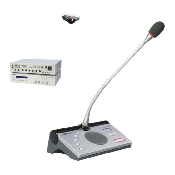
2.1 Overview HCS-5300M/80 digital infrared wireless conference Types: system main unit is the heart of the HCS-5300/80 HCS-5300MA/80 wireless conference system. The main unit can be Digital IR Wireless Conference System Main Unit connected to digital infrared transceivers and recording... -
Page 23: Functions And Indications
2.2 Functions and indications Front panel of HCS-5300M/80 main unit Rear panel of HCS-5300MA/80 main unit Rear panel of HCS-5300MB/80 main unit Rear panel of HCS-5300MC/80 main unit Figure 2.1 New generation digital infrared wireless conference system main unit... - Page 24 Front panel: Backside: 1. “STANDBY” button 14. Ethernet For communication between the conference 2. “MENU” button The LCD displays the initial user interface: press main unit and the PC under TCP/IP protocol to this button to enter the LCD set-up menu; realize remote controlling;...
-
Page 25: Installation
2.3 Installation HCS-5300M/80 series new generation digital infrared wireless conference system main unit can be fixed in a standard 19-inch cabinet. The main unit is equipped with a pair of fixing brackets ①. First unscrew the lateral screws ② from the housing. Then fasten the brackets with these screws and put the main unit in the cabinet. -
Page 26: Connection
2.4.2.2 To recording device connected to interpretation devices (please refer to 2.6.2). HCS-5300M/80 series new generation digital infrared TAIDEN interpreter units can be connected directly to wireless conference main unit has 2 audio outputs and 8 HCS-5300M/80 from interpreter’s unit interface and fulfill... -
Page 27: To Hcs-8300Mi Series
2.4.2.3 To PA HCS-5300M/80 series new generation digital infrared wireless conference system main unit has audio output interfaces which can be connected to a PA system. Use an audio cable to connect “LINE OUT 1” or “LINE OUT 2” of HCS-5300M/80 to the input interface of PA. Figure 2.7 Digital infrared wireless conference main unit connecting to PA 2.4.3 To HCS-8300MI series... -
Page 28: System Connection 1
2.4.4 System connection 1 [Wired/wireless discussion + digital simultaneous interpretation + voting + video tracking] HCS-5300MA/80 has the functions for discussion, vote board and high-speed dome camera. and digital simultaneous interpretation. The system can Use a RS-485 cable and connect the HCS-5300M/80 be connected to an automatic video tracking system. -
Page 29: System Connection 2
LAN or internet. The automatic video tracking system is compatible with If using TAIDEN network central control system touch several kinds of video signals and operates automatic panel to control conference units, the ID of each video switching. - Page 30 Figure 2.10 System connection [Wired/wireless discussion + digital simultaneous interpretation + video tracking + central control]...
-
Page 31: System Connection 3
The automatic video tracking system is through LAN or internet. compatible with several kinds of video signals and If using TAIDEN intelligent central control system touch operates automatic video switching. The video tracking panel to control conference units, the ID of each... - Page 32 Figure 2.11 System connection [Wireless discussion + video tracking + central control]...
-
Page 33: Load Capacity
2.4.7 Load capacity HCS-5300MA/MB/80 main unit can connect to and power for digital infrared wireless transceiver, wired congress unit and interpretation unit. So, devices type and quantity must be considered synthetically when designing a system. The HCS-5300M/80 main unit can connect to 10 transceivers at most. -
Page 34: Configuration And Operation
2.5 Configuration and operation Digital infrared wireless conference system main unit can in the system, the chairman unit can be activated till be configured and set up through menu operation with the number reaches 4 and then if another chairman four buttons. -
Page 35: System Status
“Dante Audio Mode” b) Microphone Battery Status “Set RS-232 Baudrate” Use the “/” button to select “Microphone Battery “Noise Elimination” Status” and use the “MENU” button to confirm. “Line Out1 Noise Gate Setting” The ID, voltage and residual time of the active “About”... - Page 36 If “0” is selected, it stands for no SI function, use the “MENU” button to save and return to the main menu; If other values are selected, it stands for the number of interpretation channels, use the “MENU” button to go to step b).
-
Page 37: Line In 2 Setting
h) Interp. Units Green LED Enable/disable to switch the interpretation units green LED. 2). Press the “/” button to select auto-relay booth quantity and press the “MENU” button to go to the next step; 1). Press the “/” button to select “Enable” or “Disable”;... -
Page 38: Downlink Audio Treble Setting
2.5.5 Downlink Audio Treble Setting 2.5.7 Headphone Auto Att. (Attenuation) Setting Adjust downlink treble of the floor, range: -15dB - +15 If a headphone is plugged, howling may happen when the microphone is activated. “Headphone auto att.” a). Press the “/” button to adjust; function is used to suppress howling for floor language b). -
Page 39: Microphone Parameters Setting
2.5.10 Microphone Parameters Setting 4. “Microphone Low Cut Setting” 1. “Microphone Gain Setting” a). Press the “/” button to select “On” or “Off”; b). Press the “MENU” button to save and return to the a). Press the “/” button to select “Set All Mics” or upper level menu. -
Page 40: Language
b). Press the “MENU” button to save and return to the Note: next carrier setting interface; “IP address”, “Subnet Mask” and “Gateway” of c). After all carriers are set, press the “MENU” button to the system software must correspond with the save and return to the upper level menu. -
Page 41: Si Channel Parameters Setting
2.5.17 SI Channel Parameters Setting 2.5.19 Alarm Setting Set the parameters of the SI channel. Enable/disable alarm function. a). Press the “MENU” button to view the channel state. a) Press the “/” button to select “Yes” or “No”; If a channel hasn't been fed with language output b) Press the “MENU”... -
Page 42: Wiredmic Function Setting
b). Press the “MENU” button to save and return to the b). Press the keys on the wired units one by one to upper level menu. number each unit, the button indicating light will be deactivated; “Auto Turn Off Time” c). -
Page 43: Mic. Led Setting
External Process: If selecting analog interface for 2.5.25 Mic. Led Setting external processor, LineOut1 and LineOut2 output Set up the color of indicator lamp rings when turn on the feature each the sum signal of Dante In + LineIn2 microphone and the “ON/OFF”... - Page 44 Figure 2.13 Audio mode setting – Normal Mode Figure 2.14 Audio mode setting – Remote Conferencing Mode1...
- Page 45 Figure 2.15 Audio mode setting – Remote Conferencing Mode2 Figure 2.16 Audio mode setting – External Process Mode1...
- Page 46 Figure 2.17 Audio mode setting – External Process Mode2...
-
Page 47: Usb Audio Setting
2.5.27 USB Audio Setting 2.5.30 Set RS-232 Baudrate Enable/disable USB audio function. The USB audio will Set the baudrate of RS-232. engage one SI channel. a) Press the “/” button to select “9600” or a) Press the “/” button to select “Yes” or “No”; “115200”;... -
Page 48: About Dante
2.5.34 About Dante Dante information includes: Dante version, device version and device name, as shown in the following figure - press any button to return to the upper level menu. b). Press the “/” button to select “Disable” or “Enable”; ... -
Page 49: Usb Audio
2.6 USB Audio HCS-5300M has a built-in USB Audio (1 channel, 16bit, 32kHz) which can be connected to the computer through USB cable (software requirement: WindowsXP or higher) for digital audio input/output. We take Win7 system as an example to introduce the function and operation of the USB Audio. -
Page 50: Digital Audio Input
2.6.2 Digital audio input When the HCS-5300M main unit is connected to the computer, the conference units connected in the system are the microphone for digital audio input. Using the recording software or the third party communication software, such as recorder, Skype or QQ and so on, functions like recording, remote instruction, remote communication can be implemented. -
Page 51: Digital Audio Output
2.6.3 Digital audio output The HCS-5300M main unit can be connected to the computer for digital audio output. Please adjust and test the HCS-5300M UBS Audio to a suitable volume when first using. Adjust method: open the control panel-sound (or right click the volume icon on the taskbar and select sound), and select the speakers (HCS-5300M UBS Audio) and modify its setting in the Playback dialog box, as shown in the following figure: Figurer2.20: Adjusting playback volume... -
Page 52: Chapter 3 Digital Infrared Transceiver
Chapter 3 Digital infrared transceiver 3.1 Overview digital infrared transceiver manages communication between main unit conference units. It can be mounted onto the ceiling or the wall for optional coverage or fixed onto a tripod at any appropriate spot. Types: HCS-5300TD/80 Digital Infrared... -
Page 53: Functions And Indications
3.2 Functions and indications 3.2.1 Digital infrared transceiver HCS-5300TW/80 digital infrared transceiver Figure 3.1 HCS-5300T digital infrared transceiver HCS-5300TD Digital infrared transceiver Figure 3.1: 2-meter 6 PIN cable CBL-5300 Power indicating light Switchers for radiation area selection Power adapter port (connect to HCS-ADP24V) Note: ... -
Page 54: Digital Infrared Cable Splitter
3.2.2 Digital infrared cable splitter HCS-5352 digital infrared cable splitter with one input and four outputs that can be used to connect four transceivers/ receivers at most. Figure 3.2 HCS-5352 cable splitter Figure 3.2: 1. To the transceiver interface of the main unit 2. -
Page 55: Infrared Service Area
3.3 Infrared service area a.HCS-5300TD(S)/80 b.HCS-5300TH/80 c.HCS-5300TW/80 Mounting Coverage area Mounting Coverage area Type No. Type No. height (H) radius (R) height (H) length (R) 2.5 ~ 3.0 m 13 m ≤ 5 m HCS-5300TW/80 1 ~15 m HCS-5300TD/80 3.5 ~ 4.5 m 11 m HCS-5300TDS/80 * The table above is the coverage area of a single... -
Page 56: Position Planning
3.4 Position planning 3.4.1 Precautions in planning the digital infrared Note: transceiver/receiver If the position of lighting equipment is higher than the position of the transceiver/receiver, its Due to strict demands on intensity and stability of disturbance can be ignored. infrared signals in an infrared wireless conference system, please read section 1.4 carefully and take all aspects of infrared signal transmission into consideration... - Page 57 3.4.1.4 Make each conference unit communicating with more than one transceiver As shown in the following figure: when the speaker in the front row speaks in an upright position, the infrared signal will be blocked. In conference rooms with conference units in rows, each conference unit should communicate with more than one transceiver to avoid blocking.
-
Page 58: Planning Digital Infrared Transceiver
3.4.2 Planning digital infrared transceiver The coverage area of the digital infrared transceiver is defined by the distance between the transceiver and the conference unit. Select suitable transceiver type according to the height of the conference room, locate them at reasonable positions and place all conference units within the coverage area. - Page 59 3.4.2.2 Example for planning the transceiver 【Square table arrangement】 【Rectangular table arrangement】 If the transceivers are arranged as shown in the following Generally: conference rooms with identical figure, the coverage area of infrared signals will cover dimensions, position transceivers the entire meeting room. determined by the arrangement of the conference units (Figure 3.15 and 3.17) The following figures show the ideal position planning of...
- Page 60 A) Conference style seating (circulatory seating) B) Parliamentary seating Within the circulatory seating operating area of the If the transceivers for parliamentary seating would be conference units, the transceivers must be placed evenly. placed evenly as shown in Figure 3.14, transceiver No. 1 Make sure that all conference units communicate with at could only communicate with the few conference units in least two transceivers.
-
Page 61: Planning The Path From Main Unit To Transceiver
3.4.3 Planning the path from main unit to transceiver 【Chairman platform】 To get awider and farther coverage area within 5 meters 3.4.3.1 Cautions for cable connecting height, HCS-5300TW/80 digital infrared transceiver is The distances between main unit and every strongly recommended for the meeting place where the transceiver must be equal height is lower than 5 meters, such as chairman platform. - Page 62 3.4.3.2 Using distributor If using distributors, do not use more than one distributor in one branch, or it will increase high frequency signal loss and may cause system fault. Connections to transceivers with and without distributors in the branch, cannot work together in one system. When installed in several rooms, the cable splitter must be connected to the main unit directly and the cable lengths to different rooms do not need to be equal, as shown in...
-
Page 63: Installation
3.5 Installation 3.5.1 Installation of HCS-5300TD/80 3.5.1.1 Ceiling mounted 1 ① HCS-5300TD/80 digital infrared transceiver ② HCS-5300TD/80 digital infrared transceiver ceiling-mounting kit ③ Mounting hole (drilled on the ceiling) ④ Ceiling Figure 3.22 HCS-5300TD/80 digital infrared transceiver ceiling mounted Mounting steps: Step 1: Install the ceiling mounting kit at the top of the HCS-5300TD/80 Transceiver;... - Page 64 3.5.1.2 Ceiling mounted 2 ① M3 screw ② Hard ceiling mounting bracket ③ Rubber plug ④ Hard ceiling (such as concrete ceiling) ⑤ HCS-5300TD/80 digital infrared transceiver Figure 3.23 HCS-5300TD/80 digital infrared transceiver ceiling mounted Mounting steps: Step 1: Position the mounting bracket on the ceiling according to the installation location of the HCS-5300TD/80 and mark the positions of the drilling holes.
- Page 65 3.5.1.3 Tripod mounted (Adjustable angle) ① HCS-5300TD/80 digital infrared transceiver ② M3 screw ③ Wall-mounted bracket (with flexible tube) ④ Tripod-mounted stator ⑤ HCS-5300TZJ2 (should be ordered separately) Figure 3.24 HCS-5300TD/80 digital infrared transceiver tripod mounted Mounting steps: Step 1: Fix the HCS-5300TD/80 digital infrared transceiver onto the wall-mounted bracket with M3 screws;...
- Page 66 3.5.1.4 Tripod mounted ① Hard ceiling mounting bracket ② HCS-5300TD/80 digital infrared transceiver ③ HCS-5300TZJ2 (should be ordered separately) Figure 3.25 HCS-5300TD/80 digital infrared transceiver tripod mounted Mounting steps: Step 1: Put the bracket on the bottom of the transceiver and fix it with rotation; Step 2: Aim the mounting hole at the bottom of HCS-5300TD/80 digital infrared transceiver to the screw on the tripod;...
- Page 67 3.5.1.5 Wall mounted (Adjustable angle) ① HCS-5300TD/80 digital infrared transceiver ② M3 screw ③ Wall-mounted bracket (with flexible tube) ④ Wall Figure 3.26 HCS-5300TD/80 digital infrared transceiver wall mounted Mounting steps: Step 1: Fix the HCS-5300TD/80 digital infrared transceiver onto the wall-mounted bracket with M3 screws;...
-
Page 68: Installation Of Hcs-5300Tds/80
3.5.2 Installation of HCS-5300TDS/80 ① M6×60 hook up riveting bolt ② M4 screw(M4×40)and nut ③ User customized suspension (see figure 3.30 for requirements) or HCS-5300TDP suspension (optional length) ④ M3×12 screw ⑤ Hard ceiling (such as concrete ceiling) Figure 3.27 HCS-5300TDS/80 digital infrared transceiver suspension mounted Mounting steps: Step 1: Fix M6×60 hook up riveting bolt onto the hard ceiling (such as concrete ceiling);... - Page 69 Figure 3.28 Requirements of user customized suspension...
-
Page 70: Installation Of Hcs-5300Th/80
3.5.3 Installation of HCS-5300TH/80 3.5.3.1 Ceiling mounted ① HCS-5300TH/80 digital infrared transceiver ② HCS-5300TH/80 digital infrared transceiver ceiling-mounting kit ③ Mounting hole (drilled on the ceiling) ④ Ceiling Figure 3.29 HCS-5300TH/80 digital infrared transceiver ceiling mounted Mounting steps: Step 1: Install the ceiling mounting kit at the top of the HCS-5300TH/80 Transceiver; Step 2: Drill a hole with 98 mm diameter into the ceiling (for mounting and heat elimination during operation);... - Page 71 3.5.3.2 Tripod mounted (Adjustable angle) ① HCS-5300TH/80 digital infrared transceiver ② M3 screw ③ Wall-mounted bracket (with flexible tube) ④ Tripod-mounted stator ⑤ HCS-5300TZJ2 (should be ordered separately) Figure 3.30 HCS-5300TH/80 digital infrared transceiver tripod mounted Mounting steps: Step 1: Fix the HCS-5300TH/80 digital infrared transceiver onto the wall-mounted bracket with M3 screws; Step 2: Fix the tripod-mounted stator onto the other end of the wall-mounted bracket with M3 screws;...
- Page 72 Wall mounted (Adjustable angle) ① HCS-5300TH/80 digital infrared transceiver ② M3 screw ③ Wall-mounted bracket (with flexible tube) ④ Wall Figure 3.31 HCS-5300TH/80 digital infrared transceiver wall mounted Mounting steps: Step 1: Fix the HCS-5300TH/80 digital infrared transceiver onto the wall-mounted bracket with M3 screws; Step 2: Position the wall-mounted bracket on the wall according to the installation location of the HCS-5300TH/80 and mark the positions of the drilling holes.
-
Page 73: Installation Of Hcs-5300Tw/80
3.5.4 Installation of HCS-5300TW/80 ① M3 screw ② Rubber plug ③ Wall ④ HCS-5300TW/80 digital infrared transceiver Figure 3.32 HCS-5300TW/80 digital infrared transceiver wall mounted Mounting steps: Step 1: Drill two holes (5 mm diameter, 30 mm depth and 100.6 mm interval) into the wall;... -
Page 74: Connecting To Main Unit
3.6 Connecting to main unit Connect the transceiver to the main unit with designated 6-pin 100 Mbps high speed cable (see figure 3.33). Figure 3.33 Digital infrared transceiver connecting to digital infrared wireless conference main unit Note: The correctness of the cable connection can be ascertained if the indicating light on the transceiver is lighting up. -
Page 75: Chapter 4 Digital Infrared Wireless Conference Unit
Chapter 4 Digital infrared wireless conference unit 4.1 Overview HCS-5300/80 series digital infrared wireless conference units are the basic devices for the participators, divided into delegate unit and chairman unit with priority features. Different functions are available, depending on the conference unit type used. -
Page 76: Functions And Indicating
4.2 Functions and indicating HCS-5300CE/80 HCS-5300DE/80 HCS-5302D/80 HCS-5302C/80 Bottom side HCS-5301D/80 Left side ( functions for 5301D/80 only ) Right side Figure 4.1 HCS-5300/80 series new generation digital infrared wireless conference unit... - Page 77 Figure 4.1: the priority button to activate it; 1. Infrared transmitting/receiving glass – at the frontage of the conference unit for transmitting/ If “Ring” mode was set as “On” in the main unit receiving infrared signals. configuration, pressing this button will emit a ring tone.
- Page 78 Start/Stop/Candidate5/Response++ (“START/STOP/5/++”): In questionnaire/opinion poll state of voting mode, voting indicating light will blink, press this button to vote for candidate 5; In audience response/rating state of voting mode, voting indicating light will blink, press this button to give a response “100” of “100” (“++”); 10.
-
Page 79: Infrared Service Area
4.3 Infrared service area Infrared light is directional invisible light. Infrared guarantee maximum receiving angle. wireless conference unit gets best sensitivity when it In the vertical direction, the emission angle is 125°, directly faces a transceiver. Every HCS-5300/80 series and in the horizontal , the emission angle is 120°. new generation digital infrared wireless conference unit is equipped with infrared glass at its frontage to Figure 4.2 Coverage area of new generation digital infrared wireless conference unit... -
Page 80: Precautions In Using
4.4 Precautions in using Avoid direct sunshine when using, otherwise it The distance between the conference unit and may cause signal blocking. the nearest transceiver must be at least 2 meters or more. Figure 4.3 Close curtain to avoid direct sunshine ... -
Page 81: Operation
4.5 Operation reached, pressing the “Mic. On/Off” button will turn on the microphone; The operation of the chairman unit and the delegate unit If the Mic. active limit has been reached, the will be introduced in detail in this section. delegate microphone switched on first will be switched off first automatically (first in / first out) 4.5.1 The operation of delegate unit... - Page 82 For “Last key-press valid” voting, the delegate can Key press sign-in (application software needed) change his/her vote. When the delegate voted, the In sign-in mode, sign-in indicating light will blink. Press indicating light of his voted key will be activated and the “Attend”...
-
Page 83: The Operation Of Chairman Unit
4.5.2 The operation of chairman unit The chairman unit features the functions of a delegate unit and in addition priority function: If the priority mode is set as “All mute” in the main unit configuration, all active conference units will be muted when the priority button on the chairman unit is pressed and return active when the priority button on the chairman unit is released;... -
Page 84: Chapter 5 Web Control Software
Chapter 5 Web control software Apply model: HCS-5300MA/80、HCS-5300MB/80、HCS-5300MC/80; Running environment: browser for Firefox29.0, Google25.0, IE10 or higher. 5.1 Login and exit The user inputs the IP address of the CMU into the Web browser to login. The default UserName is “admin” and the default password is “123456”, the password can be changed after login. - Page 85 Input the UserName and password, then click the “Login” button and it will enter the conference management system interface automatically. Figure 5.2 Conference Management System There are two buttons in the right top of the interface: Password Change: click this button and the below dialog box is shown: Input the Old Password, New Password and Password Confirm, and then click the “OK”...
-
Page 86: Conference Management
5.2 Conference management 5.2.1 Assign unit ID to delegate It will list all ID of connective units in the system. User can assign them to delegates, open microphones, set up the camera predefine position, etc.. The interface is shown in the following figure: Figure 5.3 Assign Unit ID to Delegate ... -
Page 87: Speaking And Request List
5.2.2 Speaking and request list Speaking and Request List displays the information of the active and requested microphones, includes Mic. ID, delegate name, camera control and unit type. Figure 5.4 Speaking and Request List Turn Off All Mic.: turn off all the microphones on the speaking list; ... -
Page 88: Cmu Setting
5.2.3 CMU setting CMU Setting includes Operation Mode, Active Microphones and Loudspeaker Volume. The CMU Setting interface as shown in the following figure: Figure 5.5 CMU Setting Operation Mode: set up the speaking mode, include Open/ Override/ Voice/ Apply; ♦... -
Page 89: Video Matrix
5.2.4 Video matrix It includes Video Matrix and Video Switch. The matrix, TMX-0804, is a high definition video matrix which includes one 8x4 video matrix. 5.2.4.1 Video Matrix The setup of the Video Matrix interface is shown in the following figure: Figure 5.6 Video Matrix ... - Page 90 5.2.4.2 Video Switch The interface of the Video Switch is shown in the following figure: Figure 5.7 Video Switch Matrix switch: According to the setup of the video matrix, the video input type will be displayed automatically; Assign corresponding output channel by clicking on the cross point of input and output; Select “Video Track”...
-
Page 91: Predefined Position
5.2.5 Predefined position If the conference system is equipped with cameras, the system can carry out automatic video tracking, i.e. display the image of the speaking participator to the display devices (large screen, TV, and so on). Predefine position is to set the predefined position of each microphone. -
Page 92: Setup
5.2.6 S.I. setup It includes channels, booths and language setting. The interface of S.I. setup is shown in the following figure: Figure 5.9 S.I. setup Channels: supports 7 S.I. channels at most. If there are wired conference units connected, the maximal number of channels is 3;... - Page 93 Note: The user-defined language only supports a sequence of numbers or letters (case sensitive) with a maximum of 8 characters, the abbreviation supports a maximum of 3 characters.
-
Page 94: Chapter 6 Accessories
Chapter 6 Accessories 6.1 Digital IR conference room switcher 6.1.1 Functions and indications Front panel of HCS-5300MX Rear panel of HCS-5300MX Figure 6.1 HCS-5300MX Digital IR Conference Room Switcher 7. Input channels(1-4) 1. Mains switch For connecting to HCS-5300M Digital IR Wireless 2. -
Page 95: Connection
6.1.2 Connection 6.1.2.1 Splitting/Combining several meeting rooms 1 Several meeting rooms can be split/ combined at leisure through the HCS-5300MX Digital IR Conference Room Switcher with CBL5300 cable. One HCS-5300MX can combine up to four meeting rooms. Figure 6.2 Splitting/Combining several meeting rooms 1... - Page 96 6.1.2.2 Splitting/Combining several meeting rooms 2 Several meeting rooms can be split/combined at leisure meeting rooms can be combined up at most to realize through the HCS-5300MX with CBL5300 cable to discussion, 1+7CHs simultaneous interpretation, central connect the transceivers and the HCS-8300MX with control, etc..
-
Page 97: Configuration And Operation
6.1.3 Configuration and operation Switch on HCS-5300MX Digital IR Conference Room Switcher, it will start initialization: When the initialization is finished, the corresponding state of input channels and output groups will be displayed on the LCD: Press the button at the front panel and go to the next operation: ... -
Page 98: Accessories
6.2 Accessories HCS-5300 can be power supplied by specific Lithium Disassemble procedure: battery or power adapter. 1. Press and hold the buckles on the right and left side of the battery; 2. Plug the battery out according to the arrow direction on the battery. -
Page 99: Charging Device
6.3 Charging device 6.4 Power adapter The charging unit can recharge up to 8 HCS-5300BAT HCS-ADP15V power adapter batteries at one time by using universal power supply Connect the HCS-ADP15V to the power adapter with automatic voltage matching. A charging indicator interface at the bottom of the HCS-5300/80 series new and a fully charged indica or on the charging unit are... -
Page 100: Dedicated Extension Cable For Digital Infrared Transceiver
6.5 Dedicated extension cable for digital 6.6 HCS-5300TZJ2 transceiver stand infrared transceiver CBL5300 dedicated cable is used to connect the digital infrared transceiver and the digital infrared wireless conference main unit. It features one male 6P-DIN connector at one end and one female 6P-DIN connector at the opposite end. -
Page 101: Earphones
6.7 Earphones The earphones are connected to the conference units via an Ø 3.5 mm stereo jack. Suitable earphone types include: HCS-5100PA headphone EP-820AS single earphone EP-829 single earphone EP-960BH headphone EP-829SW single earphone Any other compatible type (see chapter Technical Data). -
Page 102: Chapter 7 Fault Diagnosis
Chapter 7 Fault diagnosis Some simple trouble-shooting instructions are provided in this chapter. If more serious faults arise, please contact a qualified technician. 7.1 Digital infrared wireless conference unit Fault Analysis Solution The battery is not charged when leaving The battery is not charged (When using the factory, please fully charge the battery the lithium-ion battery) Cannot startup. -
Page 103: Digital Infrared Wireless Main Unit
Change the fuse. powered on. The fuse has blown. Please contact the local TAIDEN service center. Plug-in the battery properly into the The charging indicating light of The battery is not properly plugged-in. -
Page 104: Chapter 8 Technical Data
Chapter 8 Technical data 8.1 System specification System environmental conditions System performance Working conditions fixed/stationary/transportable Conforms to IEC 60914, the international standard for Temperature range: conference systems - Transport: -40 °C to +70 °C The carrier frequency (0~3) transmitted by the main unit - Operating: 0 °C to +45 °C conforms to IEC 61603-7, the international standard for Max. -
Page 105: New Generation Digital Infrared Wireless Main Unit
8.2 New Generation Digital infrared wireless main unit Type HCS-5300MA/80 HCS-5300MB/80 HCS-5300MC/80 √ √ √ Discussion Simultaneous interpretation Max. (1+7) channels Max. (1+7) channels √ Vote √ Dante Mains voltage AC 100 V-120 V 60 Hz or AC 220 V-240 V 50 Hz Power consumption Max. -
Page 106: Digital Infrared Transceiver
8.3 Digital infrared transceiver Type HCS-5300TD/80 HCS-5300TDS/80 Voltage 33 V DC (supplied from HCS-5300) Max. 550 mA Current consumption Tripod, wall or ceiling mounted Suspension Mounting Wavelength 870 nm Modulation method DQPSK Carrier frequency 1 ~ 8 MHz Area radius from the point underneath the unit Approx. - Page 107 Type HCS-5300TH/80 HCS-5300TW/80 33 V DC(supplied from HCS-5300M) Voltage 24 V DC(supplied from HCS-ADP24V) Max. 550 mA Current consumption Tripod, wall or ceiling mounted Wall mounted Mounting Wavelength 870 nm DQPSK Modulation method Carrier frequency 1 ~ 8 MHz Area radius from the point underneath the unit Approx.
-
Page 108: New Generation Digital Infrared Wireless Conference Unit
8.4 New Generation Digital infrared wireless conference unit Type HCS-5300CE/80 HCS-5300DE/80 HCS-5301D/80 HCS-5302D/80 HCS-5302C/80 √ √ √ √ √ Discussion Voting 5 keys 2×(1+7) Simultaneous interpretation 1+7 channels 1+7channels channels √ √ Priority key Voltage 11.1 V DC (HCS-5300BAT battery); 15 V DC (HCS-ADP15V power adapter) When Mic on: 320 mA Current consumption When Mic off: 65 mA... - Page 109 Type HCS-5300CE/80 HCS-5300DE/80 HCS-5301D/80 HCS-5302D/80 HCS-5302C/80 Weight (excl. battery) 0.5 kg Weight (incl. battery) 0.8 kg Color Silver/ Charcoal gray Type Uni-directional electret condenser microphone Sensitivity -46 dBV/Pa Frequency response 30-20000 Hz Directivity 0°/180° >20 dB (1kHz) Equivalent noise 20 dBA (SPL) Maximum sound 125 dB (THD<3%) pressure level...
-
Page 110: Digital Ir Conference Room Switcher
8.5 Digital IR Conference Room Switcher Type HCS-5300MX Mains voltage AC 100 V - 120 V 60 Hz or AC 220 V - 240 V 50 Hz 15 W Power consumption 4 6P-DIN sockets Input interfaces 20 6P-DIN sockets in 4 groups, 5 sockets per group Output interfaces Dimensions Weight... -
Page 111: Charging Device
8.7 Charging Device Type HCS-5300CHG/08 Mains voltage AC 100 V - 240 V 50/60 Hz Power consumption Max. 380 W Charging Time Approx. 6 hours Charging Capacity 8 HCS-5300BAT batteries Power indicator LED indicator Charging status (Green: Full charge or battery not inserted, Red: On charge) Dimensions Weight 4.5 kg... -
Page 112: Distributor
8.9 Distributor Type HCS-5352 Voltage 33 V DC (supplied from HCS-5300M) Number of I/O terminals 1 In / 4 Out Connector 4 x 6P-DIN socket + 2.1 m cable with 6P-DIN plug Dimensions 149 (w) x 35 (h) x 90 (d) mm Weight 0.3 kg Color... -
Page 113: Earphones
8.12 Earphones EP-820AS Single Earphone EP-960BH headphone Used with the receiver/conference unit Used with the receiver/conference unit Hi-Fi sound quality Hi-Fi sound quality Ø 3.5 mm stereo plug 150 Ohm×2, Ø 3.5 mm stereo jack ... -
Page 114: Connection Details
8.13 Connection details Mains cables Blue Neutral Brown Live Green/Yellow Earth/Ground Audio cables Chinch connector (male) Pin① Signal + Pin② GND Earphones 3.5 mm Jack plug Tip① Signal left Ring② Signal Right Sleeve③ Electrical earth/screen Emergency switch Terminal block Connect the emergency switch to +, -. - Page 115 8.14 Display language list № № № Chinese English Abbr. Chinese English Abbr. Chinese English Abbr. 原声 巴厘语 加利西亚语 Floor Balinese Galician 阿尔巴尼亚 孟加拉国语 古吉特语 Albanian Bengali Gujarati 阿拉伯语 缅甸语 夏威夷语 Arabic Myanmar Hawaiian 保加利亚语 白俄罗斯语 坎那达语 Bulgarian Belarusian Kannada 加泰罗利亚...
- Page 116 Appendix Dedicated 6 PIN Extension Cable...
- Page 117 TAIDEN INDUSTRIAL CO., LTD. 6/F, Block B, Future Plaza, 6060 Qiaoxiang Rd, Nanshan District, Shenzhen,China P.C.: 518053 Copyright by TAIDEN Website: http://www.taiden.com Last Revision: 03/2018...
Need help?
Do you have a question about the HCS-5300MA/80 and is the answer not in the manual?
Questions and answers