Table of Contents
Advertisement
Advertisement
Table of Contents

Related Manuals for digicon catrax automatic master


Summary of Contents for digicon catrax automatic master
- Page 1 Product Manual...
- Page 3 Digicon S.A. Manual code: 069.31.202 English - Revision: 02 This manual was elaborated by: Digicon S.A. Controle Eletrônico para Mecânica Documentation Sector - EDS...
-
Page 4: Table Of Contents
Contents 1. mportant Instructions ........... 2. Orientations ..............3. Introduction ..............4. Features of Automatic Master .......... 4.1 Automatic Master Operation ........... 5. Installing/Assembling ............. 5.1 Unboxing ..............5.2 Floor drilling and column fixation ........5.3 Assembling the arms ........... 5.4 Access to Automatic Master after assembly ...... -
Page 5: Mportant Instructions
You can see, below, the symbols that will appear in this manual, signaling important moments. It is essential to pay attention to them. TIP: Indicates something Digicon considers important. CAUTION: Indicates a moment of extreme caution when handling the equipment/product ATTENTION: Indicates a moment when your observation skills should be extremely productive. -
Page 6: Orientations
Keep this manual for future consultations. Ÿ Digicon reserves its right to alter its products at any moment to adapt them to more Ÿ recent technical advancements. Digicon maintains its right to alter the information contained in this manual without Ÿ... -
Page 7: Features Of Automatic Master
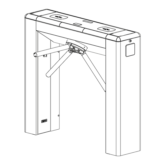
4. Features of Automatic Master Automatic Master, an access controller in the model blockage, presents three bidirectional, equidistant arms at 120 degrees with brushed stainless steel (AISI 304) finishing. The structure of Automatic Master can present external finishing in brushed stainless steel (AISI 304) or 1020 carbon steel with electrostatic painting in black epoxy powder. -
Page 8: Automatic Master Operation
Besides compatibility with most available technologies, Digicon can provide the following optional items: collecting kit with box, pictogram kit, counter kit, power supply, power supply, control board, and display kit. These items are described in details in item 6. Installing/Assembling optional items. -
Page 9: Installing/Assembling
As the items inside the package can vary (depending on the client's requests), it is important to perform a cautious visual inspection before installing and assembling the turnstile. A checklist that works as a guide during inspection accompanies all Digicon packages. See below the parts that can compose Automatic Master:... -
Page 10: Floor Drilling And Column Fixation
5.2 Floor drilling and column fixation Before installing Automatic Master, check: 1. if the floor has conditions to receive anchor bolts (at least 4cm of FCK15 M.P.A. concrete or equivalent) 2. If there is a power source or electric socket nearby (ducts for connection). 3. -
Page 11: Assembling The Arms
5.3 Assembling the arms After positioning and aligning the turnstile in its operation place, it's time to assemble the arms. Make sure that you have all the necessary items and that the turnstile is turned off, once you will have to remove the bowl to screw in the arms. The arms are provided disassembled. - Page 12 5.4 Accessing the turnstile after assembly After Automatic Master is installed and assembled, access to the interior of the equipment can be done with the key that accompanies the equipment, in three ways: external covers, central cover, or column door. See now the instructions for opening Automatic Master after assembly: 1.
- Page 13 3. Open the cover according to the following images: Note that the equipment structure contains a device that maintains the cover in the vertical position (see detail). 4. The following image shows Automatic Master with all covers open. INFORMATION: To access the column door, remove the external cover on the appropriate side.
-
Page 14: Connection To Power Network
The Turnstile is powered by a 24 Vcc supply (located inside the turnstile). The power supply can be of 100 to 240 Vca. Digicon recommends the regulation NBR 5410 as reference to the equipment's electrical connections. In one of its columns, the turnstile has circuit breakers in its columns where the power cables (electrical supply) and the ground wire must be connected. -
Page 15: Installing/Assembling Operational Items
Automatic Master is compatible with most access control technologies in the market today; however, Digicon offers a range of optional items that allow enhancing and matching the equipment's performance to the client's needs. See the description of each of these items: 6.1 Rear closure kit... -
Page 16: Collecting Box Kit
For access control board SOLENOIDE 12 11 10 9 8 7 6 5 4 3 2 1 12 11 10 9 8 7 6 5 4 3 2 1 INPUTS CN8 OUTPUTS CN9 DIGICON CONTROL BOARD BOX SENSOR ELECTROÍMAGNETS TURNSTILE SENSORS... -
Page 17: Operational Pictogram Kit
INFORMATION: - The box for cards is part of the kit and is positioned under the collecting kit. - The badge reader is not part of the kit. TIP: To obtain information on the configuration of the collecting kit, see item 6.7Control board. -
Page 18: Power Supply
TIP: To obtain information on the configuration of the pictogram, see item 6.7 Control board. 6.5 Power supply Among the main advantages of this optional item, is its adaptation capability to the voltage variations often found in installation sites – the input voltage can vary between 100 and 240 Vca. -
Page 19: Control Board
6.7 Control Board Automatic Master's control board was designed to meet most technologies of access control terminals in the market. The controller have mechanical features and layout perfectly suited for the Automatic Master's needs and it is one of the best options for the equipment's operation. - Page 20 Signal Nome/Description BOX SENSOR 1 LED anode 2 Box Signal 3 GND 4 GND JTAG – Inner use SERIAL RS - 232 2 TX 3 RX 5 GND ENGINE 1 DATE + 2 DATE - 3 GND_485 4 (+) 24V_EXT 5 GND POWER –...
-
Page 21: Inputs
OUTPUTS NO or NC Contact (HAB1 return) Contact C (HAB1 return) NO or NC Contact (HAB2 return) Contact C (HAB2 return) Output for indicative X (open collector NPN – maximum 500 mA) orange wire Output for arrow > (open collector NPN – maximum 500 mA) blue wire Output for arrow <... -
Page 22: Return Signals
Enabling passage through tension pulse is shown in the image below. It is necessary to observe the polarity of the C voltages and to use an external resistor for high voltages (110V and 220V Vac ou Vdc Vac ou Vdc 6.5.1.1 Return signals The control board has 4 return signals, two to indicate the moment, one to bob the turnstile, and one to indicate the anti-panic system's status. -
Page 23: Sound Alarm
-is not cleared and is forced during 1 second (1-second rings) -is stuck mid-turn for over 2 seconds (1-second rings) Connect the outputs according to the following image: Sound alarm Maximum current: 500mA 6.5.1.4 Connection scheme INPUTS RETURN SIGNALS OUTPUTS RALAY INPUTS OUTPUTS ACCESS CONTROL BOARD DIGICON CONTROL BOARD... -
Page 24: Pictogram
12 11 10 9 8 7 6 5 4 3 2 1 12 11 10 9 8 7 6 5 4 3 2 1 INPUTS CN8 OUTPUTS CN9 DIGICON CONTROL BOARD BOX SENSOR ELECTROMAGNETS TURNSTILE SENSORS 6.7.2 Outputs Automatic Master's board has outputs for return signals, electromagnets, pictogram, collecting box, and sound alarm. - Page 25 DIP SWITCH DS1 CHAVE Enables sound signal Disables sound signal NO inputs NC inputs Habilitation per border Habilitation per level Blocked in both directions ON ON Blocked form right to left OFF ON Blocked from left to right ON OFF Cleared in both directions OFF OFF Enables sound signal in mid-turn...
-
Page 26: Turnstile Interface
6.7.4 Turnstile Interface Enabling through Dry contact with 2 relays: Dry contact Enabling Clockwise Enabling Counter Clockwise 7654321 Enabling both ways (Clockwise and Counter Clockwise) with 1 single relay: Dry contact (simultaneos) Relay Integrator’s controller board 7654321... - Page 27 Anti panic/drop arm mechanism input: Dry contact Integrator’s controller 10987 Enabling through solid state : Vdc = 5~24V Integrator’s controller board 654321 INFORMATION: CCW: Counter Clockwise CW: Clockwise...
- Page 28 Enabling through solid state(negative): Vdc = 5~24V 54321 Integrator’s controller Activating through solid state(anti panic/Drop arm mechanism): Anti panic Vdc = 5~24V 1098 Integrator’s controller...
- Page 29 Activating through solid state (Drop arm/Negative). Vdc = 5~24V Integrator’s controller Passage confirmation Vcc - Rel logic lever, SH in ’’disk emulation’’ DIP Ds2 n°7 in mode ON. Digital positive input Integrator’s controller 4321...
- Page 30 Passage confirmation through disk emulation Passage confirmation through clockwise pulse Passage confirmation through ’’disk emulation’’ can be set through dip switch Ds2, nº7 in case it’s on it’ll emulate disk. On the other hand it’s off, it’ll general pulse. Passage confirmation(negative) Digital negative input Integrator’s controller 4321...
- Page 31 Electromechanical counter connections Depends on the couter tension protection diode In case you use inductive counter it will be necessary a protection diode Counter Inductive counter...
-
Page 32: Anti-Panic System
6.8 Anti-panic system Automatic Master has an electromechanical device for anti-panic system (also called drop-arm device). The mechanism is composed by a mechanical set activated by high-performance solenoid, maintaining the arm raised during normal operation. In case of power outage (when the installation has no no- break), or through a command sent via system, or the activation of an emergency button in the control room, the electromechanical device is deactivated, dropping the arm that prevents turn, clearing the entrance of any barrier. -
Page 33: Maintenance Test
- set the arm on the horizontal position; · turn the turnstile off; · check if the arm drops (if the arm does not drop, contact the dealer or Digicon); · turn the turnstile on; · raise the arm until it reaches its normal position (the arm must stay in horizontal position without external support;... -
Page 34: Maintenance
Maintenance 7.1Preventive and corrective routine maintenance: ATTENTION: Preventive and corrective maintenance must be performed by a professional trained/qualified by Digicon S.A. Electromagnets – Periodicity: ever 700 0 cycles This routine maintenance requires the use of a multimeter. To check for the need of corrective actions, disconnect the CN3 from the access control board and check the electromagnets' resistance. -
Page 35: Solving Problems
Solving problems Defect Possible causes Action It will not turn The power supply’s input Check the cables · · · cable is not connected and the fuse. properly The circuit breaker is off. · It does not The cable is broken or the Adjust the ·... -
Page 36: Technical Characteristcs
8. Technical characteristics 1262 ±5 INFORMATION: he arm/clip's size can be altered according to the client's needs. - Page 37 1100 Outras informações Gross weight: Approx. 100 kg (package included) Distance 120 degrees between arms Electromagnets’ 12Vcc / 2A power Power supply Input: 100 Vac to 240 Vac 60HZ Output: 24,0 Vdc +/- 5% 4,5 A Operational from 0ºC to 50ºC temperature Power Consumption during rotation is 36 W...
-
Page 38: Warranty And Technical Assistance
Warranty and technical assistance Digicon is responsible for the project, skilled labor, and quality of the materials used in the manufacturing of our products, ensuring that the equipment and all parts are free of manufacturing defects or problems. Digicon commits itself to replace or repair, as we choose, any part or equipment presenting manufacturing defects without any costs to the buyer, in our factory in Gravataí... - Page 40 Phone:(0xx51) 3489.8700 / 3489.8745 Technical assistance :(0xx51) 3489.8903 Fax: (0xx51) 3489.1026 Email: vendas.acesso@digicon.com.br Branch office/ SP Development, Technical Assistance, and Sales Street São Paulo, 82 Alphaville. Barueri/SP CEP 06465-130 Phone: (0xx11) 3738.3500 Fax: (0xx11) 4191.2585 Email: vendas.acesso@digicon.com.br Home page: www.digicon.com.br...
Need help?
Do you have a question about the catrax automatic master and is the answer not in the manual?
Questions and answers