Table of Contents
Advertisement
Quick Links
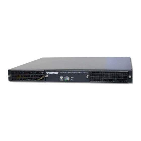
SmartNode™ SN10200A Series
TDM+VoIP Smart Media Gateway
Quick Start Guide
Important
residential environment.
Part Number: 07MSN10200-QS, Rev. G
Revised: August 24, 2018
—This is a Class A device and is not intended for use in a
Sales Office: +1 (301) 975-1000
Technical Support: +1 (301) 975-1007
E-mail: support@patton.com
www.patton.com
Advertisement
Table of Contents

Related Manuals for Patton SmartNode SN10200A Series


Summary of Contents for Patton SmartNode SN10200A Series
- Page 1 Quick Start Guide Important —This is a Class A device and is not intended for use in a residential environment. Part Number: 07MSN10200-QS, Rev. G Sales Office: +1 (301) 975-1000 Technical Support: +1 (301) 975-1007 Revised: August 24, 2018 E-mail: support@patton.com www.patton.com...
- Page 2 • Do not open the device when the power cord is connected. For sys- tems without a power switch and without an external power adapter, line voltages are present within the device when the power cord is connected. WARNING • For devices with an external power adapter, the power adapter shall be a listed Limited Power Source.
- Page 3 Gerät nicht öffnen, wenn das Netzkabel angeschlossen ist. Bei Sys- • temen ohne Netzschalter und ohne externes Netzteil liegt Netzspan- nung im Gerät an, wenn das Netzkabel angeschlossen ist. WARNING Bei Geräten mit externem Netzteil muss das Netzteil die Anforderun- •...
-
Page 4: Before You Begin
1.0 Before you begin In the box, you will find: One SmartNode 10200A • One set of mounting brackets with screws • One DB-9 to RJ-45 adapter • SCSI Cables and Patch Panels, if applicable • Three RJ45 Ethernet Straight Cables (male-male) •... -
Page 5: Connecting To The Voip Network
3.0 Connecting to the VoIP Network Connect the VoIP Ports 0/1 and 0/1 to your network (see figure Note Ethernet ports (ETH 0/0 & 0/1), and SMS ports (SMS-0/0 & 0/1) are not used when connecting VoIP. MGMT0 VOIP VoIP Ports 1–2 Figure 2. -
Page 6: Grounding The Equipment Chassis
4.3 Optical Interface (OC3/STM-1) MGMT0 VOIP OC3/STM-1 Figure 5. Connecting to the PSTN via the optical interface 5.0 Grounding the Equipment Chassis As a standard safety practice, the chassis of the SN10200A series gateway must be properly grounded to protect against any contact with an electrical fault condition. It is recommended that the chassis be connected to an earth ground. -
Page 7: Connecting To The Power Source
Do not over-tighten ground lug connections. • Keep the length of the ground wire as short as possible. • 5.2 Grounding procedure Do the following to connect to the SN10200A series gateway to ground: Connect one end of a ground wire to the ground lug of the 10200A series gate- way. - Page 8 USB connector, you will need to provide a USB to DB9 adapter. CONSOLE Port Serial Terminal (PC) Note A Patton Model 16F-561 RJ45 to DB-9 adapter is included with each SmartNode 10200A device. Figure 9. Connecting the console serial port 7.2 Connecting the Ethernet management interface...
-
Page 9: Logging Into The Smartnode Console
Log into the console using the specific credentials included on the 'Important Notice' that shipped with your unit. (If you do not have the “Important Notice” sheet, contact support@patton.com). 8.2 Accessing the SmartNode via the Ethernet Management port Logging into the SmartNode via SSH To physically connect the Ethernet management port, follow the instructions in 7.2 “Connecting the Ethernet management interface”... -
Page 10: Preparing For Web Management
This menu allows you to complete simple tasks like setting the time zone and configur- ing the management IP Address, and more complicated tasks like advanced debugging. For debugging assistance, contact Patton’s Support team at support@patton.com. Once your IP Address and Time Zone are set, there are no more configuration steps in the CLI and you may proceed to the web management page. -
Page 11: Compliance Information
AC outlet (such that the computing equipment and receiver are on different branches). A.3 CE Declaration of Conformity Patton Electronics, Inc declares that this device is in compliance with the essential requirements and other relevant provisions of Directive 1999/5/EC. The Declaration of Conformity may be obtained from Patton Electronics, Inc at www.patton.com/certifica-... -
Page 12: Customer And Technical Support
(Switzerland) Copyright statement Copyright © 2012–2018, Patton Electronics Company. All rights reserved. The information in this document is subject to change without notice. Patton Electron- ics assumes no liability for errors that may appear in this document. Trademarks statement The term SmartNode is a trademark of Patton Electronics Company. All other trade- marks presented in this document are the property of their respective owners.
Need help?
Do you have a question about the SmartNode SN10200A Series and is the answer not in the manual?
Questions and answers