Table of Contents
Advertisement
Quick Links
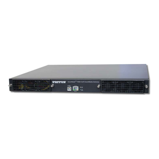
SmartNode™ SN10100A Series
TDM+VoIP Smart Media Gateway
Quick Start Guide
Important
residential environment.
Part Number: 07MSN10100-QS, Rev. C
Revised: August 24, 2018
—This is a Class A device and is not intended for use in a
Sales Office: +1 (301) 975-1000
Technical Support: +1 (301) 975-1007
E-mail: support@patton.com
www.patton.com
Advertisement
Table of Contents

Related Manuals for Patton SmartNode SN10100A Series


Summary of Contents for Patton SmartNode SN10100A Series
-
Page 1: Quick Start Guide
Quick Start Guide Important —This is a Class A device and is not intended for use in a residential environment. Part Number: 07MSN10100-QS, Rev. C Sales Office: +1 (301) 975-1000 Technical Support: +1 (301) 975-1007 Revised: August 24, 2018 E-mail: support@patton.com www.patton.com... - Page 2 • Do not open the device when the power cord is connected. For sys- tems without a power switch and without an external power adapter, line voltages are present within the device when the power cord is connected. WARNING • For devices with an external power adapter, the power adapter shall be a listed Limited Power Source.
- Page 3 Gerät nicht öffnen, wenn das Netzkabel angeschlossen ist. Bei Sys- • temen ohne Netzschalter und ohne externes Netzteil liegt Netzspan- nung im Gerät an, wenn das Netzkabel angeschlossen ist. WARNING Bei Geräten mit externem Netzteil muss das Netzteil die Anforderun- •...
-
Page 4: Before You Begin
Three CAT5 Ethernet straight cables (male-male), three meters in length • One warranty sheet • One packing slip • One SmartNode SN10100A Series Quick Start Guide • One SmartNode SN10100A Important Notice sheet with unique information for your • specific unit 2.0 Installing the rack hardware Install rack-mounting hardware on to the SN10100A and install the unit on the equipment rack. -
Page 5: Connecting To The Pstn
Ethernet ports (ETH 0/0 & 0/1), and SMS ports (SMS-0/0 & 0/1) are not used Note when connecting VoIP. VoIP Network 1 10 11 MGMT0 ETH0 VOIP0 MGMT1 ETH1 VOIP1 VoIP Network 2 Figure 2. Connecting the VoIP ports 4.0 Connecting to the PSTN A SN10100A with 8 RJ48C type ports enables the connection to T1/E1 lines. -
Page 6: Grounding Procedure
To avoid the risk of fire, electric shock, or personal injury do not apply power to the SN10100A before the equipment chassis ground has been installed. WARNING 5.1 Guidelines Use 10 AWG (minimum) stranded ground wire. • Terminate equipment side of ground wire with a #10 ring terminal. •... -
Page 7: Connecting To The Power Source
6.0 Connecting to the power source Connect AC power cables between the AC connectors of the SN10100A and the two independent power sources (see figure Verify that the Power LED on the front panel (see figure 6) is a solid green. Power Source 2 10 11... - Page 8 USB connector, you will need to provide a USB to DB9 adapter. CONSOLE Port Serial Terminal (PC) Note A Patton Model 16F-561 RJ45 to DB-9 adapter is included with each SmartNode 10200A device. Figure 7. Connecting the console serial port 7.2 Connecting the Ethernet management interface...
-
Page 9: Logging Into The Smartnode Console
Log into the console using the specific credentials included on the 'Important Notice' that shipped with your unit. (If you do not have the “Important Notice” sheet, contact support@patton.com). 8.2 Accessing the SmartNode via the Ethernet Management port Logging into the SmartNode via SSH To physically connect the Ethernet management port, follow the instructions in 7.2 “Connecting the Ethernet management interface”... -
Page 10: Logging Into The Web Interface
For debugging assistance, contact Patton’s Support team at support@patton.com. Once your IP Address and Time Zone are set, there are no more configuration steps in the CLI and you may proceed to the web management page. 9.0 Logging into the Web Interface This section describes how to login and navigate the SmartNode 10100A Web Portal. -
Page 11: Radio And Tv Interference (Fcc Part 15)
AC outlet (such that the computing equipment and receiver are on different branches). A.3 CE Declaration of Conformity Patton Electronics, Inc declares that this device is in compliance with the essential requirements and other relevant provisions of Directive 1999/5/EC. The Declaration of Conformity may be obtained from Patton Electronics, Inc at www.patton.com/certifica-... -
Page 12: Customer And Technical Support
(Switzerland) Copyright statement Copyright © 2013–2018, Patton Electronics Company. All rights reserved. The information in this document is subject to change without notice. Patton Electron- ics assumes no liability for errors that may appear in this document. Trademarks statement The term SmartNode is a trademark of Patton Electronics Company. All other trade- marks presented in this document are the property of their respective owners.
Need help?
Do you have a question about the SmartNode SN10100A Series and is the answer not in the manual?
Questions and answers