King gates STARG8 24 Installation And Use Instructions And Warnings
Control unit for 24v motor for sliding gates, or for one or two 24v motors for swinging gate
Hide thumbs
Also See for STARG8 24:
- Installation instructions manual (32 pages) ,
- Programming (16 pages) ,
- Installation and use instructions and warnings (24 pages)
Table of Contents
Advertisement
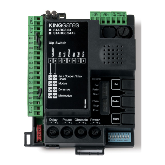
STARG8 24
EN Control unit for 24V motor for sliding gates, or for one or two 24V
motors for swinging gate
Installation and use instructions and warnings
S T
S T
D ip
-S w
1
2
O n
O n
O n
O
O
O n
O
O
Made in Italy
STARG8 24 BOX
Control unit for Jet 24, Couper,
Linear 24V or Intro 24-400
A R
G 8
A R
2 4
G 8
2 4
X L
it c
h
3
4
5
6
7
8
Je t
/ C
L in
e a r
o u
p e
r /
M o
In tr
d u
o
s
D y
n a
m o
s
M in
im
o d
P h
u s
o t o
S t o
p
R a
E r ro
d io
r
S t a
r t
Control unit for Minimodus
Control unit for
Modus280 or Modus420
Control unit for Dynamos 24
Advertisement
Table of Contents

Related Manuals for King gates STARG8 24


Summary of Contents for King gates STARG8 24
- Page 1 EN Control unit for 24V motor for sliding gates, or for one or two 24V motors for swinging gate Installation and use instructions and warnings STARG8 24 BOX Control unit for Jet 24, Couper, Linear 24V or Intro 24-400 D ip...
-
Page 2: Table Of Contents
2. Wiring 2.1 - STARG8 24 power connection 2.2 - STARG8 24 XL power connection 2.3 - STARG8 24 Accessories wiring connection of a typical system 4 2.4 - STARG8 24 power connection 3. Control unit settings 3.1 - Dip-switch adjustment 3.2 - Trimmer adjustment... -
Page 3: Product Description
Product description 1.1 - Commissioning - Possibility of powering 24VDC accessories (Paragraph 8.6). - Input for gate status pilot light signalling the position of the leaves To start-up the system, the following steps must be carried out: (Paragraph 8.7). 1 - Connect the power supply, compatible gearmotors (see Par graph - Input for external antenna that can be used for increasing the 3.1, dip 1 and 2 setting) and desired accessories as indicated in range of the transmitters (Paragraph 8.10). -
Page 4: Wiring
Wiring 2.1 - StarG8 24 power connection Line fuses (already Transformer* 230V 50Hz MAINS series connected) (already series 230V POWER SUPPLY connected) CABLE: 3X1,5mm² (max. distance 30m) (12V) MOTOR 1 (gate leaf that opens first) CABLE 2X1,5mm² MOTOR 2 (gate leaf that opens second) CABLE 2X1,5mm²... -
Page 5: Starg8 24 Xl Power Connection
2.2 - StarG8 24 XL power connection Line fuses (already Transformer* 230V 50Hz MAINS series connected) (already series 230V POWER SUPPLY connected) CABLE: 3X1,5mm² (max. distance 30m) Voltage rectifier (already series connected) MOTOR 1 (gate leaf that opens first) CABLE 2X1,5mm²... -
Page 6: Starg8 24 Accessories Wiring Connection Of A Typical System
2.3 - StarG8 24 Accessories wiring connection of a typical system Line fuses (already Transformer* 230V 50Hz MAINS series connected) (already series 230V POWER SUPPLY connected) CABLE: 3X1,5mm² (max. distance 30m) WARNING LIGHT Idea 24 Plus (12V) LAMP CABLE: 2X0.5 mm (max. -
Page 7: Starg8 24 Power Connection
2.4 - StarG8 24 Accessories wiring connection MOT2 MOT1 Warning light 24Vdc max.15W warning light (Paragraph 8.2) Default: electric lock 12Vdc max. 15W AUX contact / electric lock NB: if safety devices are connected (output configurable as courtesy light to the “PHO1” (terminal 5), “PHO2”... -
Page 8: Control Unit Settings
Control unit setting 3.1 - Dip-switch adjustment DIP SWITCHES (Paragraph 3.1) DIP-SWITCH status Description of operation DIP 1-2 ON ON Connected gearmotors: swinging series “Jet 24V”, “Linear 24V”, “Intro 24-400” or “Couper24” MOTOR ON OFF Connected gearmotors: “Modus” series swing gate OFF ON Connected gearmotor: sliding series “Dynamos 24V”... -
Page 9: Trimmer Adjustment
If the “PHO2” dip-switch is put to OFF, the safety devices for the DIP8 “FUNC”: opening phase (see Paragraph 8.6) are set as edges: they intervene SWING GATE (DIP1/2= ON ON / ON OFF/ OFF OFF) only during the opening phase by inverting the movement (thus clos- If the “FUNC”... -
Page 10: Transmitter Programming
Radio button The transmitters to be programmed must be of the “Stylo4K” or “Stylo2K” series by King Gates. See adjacent pictures. If, at the start of the following procedures, the “set”, “radio” and “start” LEDs flash, it means that the programming protections have been activated – see Paragraph 16.1. -
Page 11: Total Deletion Of Memorised Transmitters
4.3 - Total deletion of memorised transmitters This operation deletes all memorised transmitters 2. PRESS THE RADIO 1. PRESS THE RADIO 3. MEMORY DELETION COMPLETED BUTTON BUTTON FOR 4 SECONDS FOR 1 SECOND The red “radio” LED flashes The red “radio” LED flashes fast The red “radio”... -
Page 12: Programming The Gate Path
Programming the gate path Trimmer Power DIP 1 e 2 Start button Set button Radio button To start the system up, one of the following programming procedures must be carried out: - basic programming of the automation’s movement: self-learning of the manoeuvre times and of the slowdown start points. - advanced programming of the automation’s movement: self-learning of the manoeuvre times and manual setting of the slowdown start points. -
Page 13: Programming The Pedestrian Opening Width
CAUTION! - if the automation starts a closing stroke instead of an opening stroke, proceed as follows: 1. quit programming by pressing SET and RADIO at the same time: for SWING GATE MOTORS: swap the motor phases (terminals MOT1, MOT2) and the inputs of any limit switches (terminals 10-11, 13-14) for SLIDING GATE MOTORS: change the setting of DIP8, see par. -
Page 14: Advanced Programming Of The Automation's Movement
5.3 - Advanced programming of the automation’s movement With this procedure, the control unit memorises the times and power required for opening and closing the system. Moreover, this procedure allows for setting: - start point of gate deceleration area or its deletion - reverse direction of travel LEAF 1 LEAF 2... -
Page 15: Testing And Commissioning
13. FOR SLOWING DOWN THE CLOSING PHASE, DURING THE MOVEMENT PRESS THE SET BUTTON OR A PROGRAMMED TRANSMITTER BUTTON FOR 14. THE CONTROL UNIT COMPLETES SETTING THE SLOWDOWN START POINT. ALTERNATIVELY, WAIT UNTIL THE THE CLOSING PHASE MOVEMENT HAS BEEN COMPLETED The yellow “set”... -
Page 16: Led Signalling
- on in the fixed mode if the START contact (terminals 15-16) is closed - off if the START contact (terminals 15-16) is open RED RADIO LED: - flashes when a command is received through King Gates transmitter - is off when the control unit is in standby mode 7.2 - Error signalling LEDs RED “ERROR”... -
Page 17: Devices Connectable To The Pcb
DEDICATED TERMINALS: 1-2 (see Paragraph 2.4). - with the gate open they lock the closing commands. The warning light is an accessory used for signalling any movement Figures 11a, 11b and 11c show examples of King Gates “Viky30” of the gate leaf. photocell installations. - Page 18 - with the gate closed they lock the opening commands. - with the gate open they have no effect. Figures 11a, 11b and 11c show examples of King Gates “Viky30” photocell installations. If multiple devices are connected on this contact, they 8.11...
-
Page 19: 24 Vdc Accessory Power
8.6 - 24VDC accessories’ power supply If multiple START contacts are connected, connect the contacts in parallel. DEDICATED TERMINALS: 7-8 (see Paragraph 2.4). With the control unit powered, these terminals provide a nominal volt- PEDESTRIAN CONTACT (terminals 16-18) age of 24VDC, max. 250mA, and can be used for external accesso- ries such as, for example, photocells or radio receivers The pedestrian function consists of a partial opening (or full opening, depending on the installer’s preferences) of the gate leaf driven by... -
Page 20: Troubleshooting
Troubleshooting Problem Symptoms / Causes Solution 9a The control unit LEDs Mains power shortage Check for the presence of input mains voltage – see Para- are turned off graph 2.2 / 2.3 The fuses are damaged. Before replac- Replace the fuses (see Paragraph 2.3). If the fuses get ing them, disconnect the mains electric- damaged again, before replacing them disconnect all the ity and verify that there are no short-cir-... -
Page 21: Advanced Programming - Index
Advanced programming - Index The control unit is equipped with advanced programming features which are not required for commissioning the system but rather for configuring advanced functions: BACKJUMP CONFIGURATION - Backjump adjustment AUX OUTPUT PROGRAMMING - Programming the transmitter button assigned to the AUX output - Selecting the device connected to the AUX output - Selecting the AUX output mode - Selecting the AUX output voltage... - Page 22 Notes...
- Page 24 Dati dell’installatore / Installer details Azienda / Company Timbro / Stamp Località / Address Provincia / Province Recapito telefonico / Tel. Referente / Contact person Dati del costruttore / Manufacturer's details King Gates S.r.l. Phone +39.0434.737082 Fax +39.0434.786031 info@king-gates.com www.king-gates.com...
Need help?
Do you have a question about the STARG8 24 and is the answer not in the manual?
Questions and answers