Advertisement
1.
General warnings
1.1 -
Safety warnings
WARNING!
This manual contains important instructions and warnings for
personal safety.
An incorrect installation can cause serious injury. Before starting work
it is necessary to carefully read all the parts of the manual. If in doubt,
suspend the installation and request clarification from the King-Gates
Support Service.
WARNING!
According to the most recent European legislation, the
construction of a door or an automatic gate must comply with
the provisions of Directive 98/37/EC (Machinery Directive) and
in particular, the EN 1244, EN 12453, EN 12635 and EN 13241-1
5 standards which allow stating the alleged compliance of the
automation.
In consideration of this, all product installation, connection,
testing and maintenance operations must only be carried out
by qualified and competent technicians!
WARNING!
Important instructions: keep this manual for the possible
future maintenance and disposal of the product.
1.2 -
Installation warnings
• Before starting the installation, check whether this product is
suitable for automating your gate or door (see chapter 3 and the
"Technical characteristics of the product"). If it is not suitable, DO
NOT proceed with installation.
• Install a disconnecting device in the system power supply network
with a contact opening distance that allows complete disconnection
in the conditions stated by overvoltage category III.
• All installation and maintenance operations must be carried
out with the automation disconnected from the power supply.
If the disconnecting device from the power supply is not visible from
the place where the automatism is positioned, before starting work
it is necessary to attach on the disconnecting device a sign with the
inscription "WARNING! MAINTENANCE IN PROGRESS ".
• During installation, handle the automatism with care, avoiding
crushes, shocks, falls or contact with liquids of any kind. Do not
place the product near heat sources or expose it to open flames. All
these actions can damage it and cause malfunctions or dangerous
situations. If this happens, immediately suspend the installation and
contact King-Gates Customer Service.
• Do not make changes to any part of the product. Unauthorized tam-
pering can only cause malfunctions. The manufacturer declines all lia-
bility for any damages deriving from arbitrary changes to the product.
• If the gate or the door to be automated is equipped with a pedestrian
door, the system must be set up with a control system that inhibits
the operation of the motor when the pedestrian door is open.
• Check that there are no points of entrapment with fixed parts when
the gate leaf is in the maximum opening position; protect these parts
as required.
• The wall control panel must be positioned in view of the automation,
away from its moving parts, at a minimum height of 1.5m from the
ground and not accessible to the public.
• The packaging material of the product must be disposed of in full
compliance with local regulations.
1.3 -
Use warnings
• The product should not be used by people (including children) with
physical, sensory or mental disabilities, or lacking the necessary ex-
perience or knowledge, unless they are supervised by someone re-
sponsible for their safety, or have been fully trained on its use.
• Children playing nearby the automation system should be kept un-
der constant supervision to prevent them from tampering with it.
• Do not let children play with the fixed controls. Keep remote control
devices away from the reach of children.
• When cleaning the surface of the product only use a soft damp
cloth. Only use water, without detergents or solvents.
13
Advertisement
Table of Contents

Subscribe to Our Youtube Channel
Related Manuals for King gates Modus 280


Summary of Contents for King gates Modus 280
- Page 1 General warnings 1.1 - Safety warnings 1.3 - Use warnings • The product should not be used by people (including children) with WARNING! physical, sensory or mental disabilities, or lacking the necessary ex- This manual contains important instructions and warnings for perience or knowledge, unless they are supervised by someone re- personal safety. sponsible for their safety, or have been fully trained on its use. An incorrect installation can cause serious injury. Before starting work • Children playing nearby the automation system should be kept un- it is necessary to carefully read all the parts of the manual. If in doubt, der constant supervision to prevent them from tampering with it. suspend the installation and request clarification from the King-Gates • Do not let children play with the fixed controls. Keep remote control Support Service. devices away from the reach of children. • When cleaning the surface of the product only use a soft damp cloth. Only use water, without detergents or solvents.
-
Page 2: Product Description
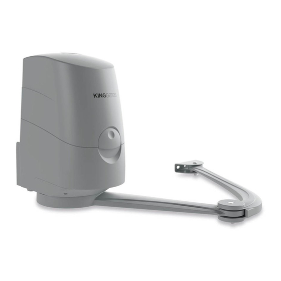
Product description This product is to be used to automate hinged gates or doors, for In the event of a power failure (black-out), it is possible to move the both residential and industrial use. leaves of the gate by hand by manually unlocking the gear motor. Fig. 1 shows all the components present in the pack (according to the chosen model): WARNING! [a] - electromechanical gear motor Any other use other than that described and in environmental [b] - arm connecting to the motor conditions other than those listed in this manual is to be considered [c] - arm connecting to the leaf improper and prohibited! [d] - leaf support bracket The product is an electromechanical gear motor, equipped with a [e] - motor unlocking key 24 V direct current motor powered by the internal control unit and a gearbox with an articulated arm. [f] - wall support bracket to secure the motor [g] - metal hardware (screws, washers, etc.) Fig. - Page 3 3.3 - Use limitations WARNING! - The single leaf must not exceed 4.2m in length. Before installing the product, check that the size and the weight of the gate leaf are within the limits stated in chart 1. kg - Maximum gate leaf weight mm - maximum gate leaf length Chart 1 - Use limitations 500 1000 1500 2000 2500 3000 3500 4000...
- Page 4 - Installation of the fixing brackets Before proceeding with the installation, make sure that value A allows to fix the rear bracket, otherwise select another point on the chart. and the gear motor Finally, to fix the bracket on the leaf, refer to the maximum dimensions of the arm in figure 3. Failure to comply with the bracket installation 3.5.1 – Installation of the rear fixing distances may lead to automation operation faults, such as: bracket - Cyclical movements and accelerations at some positions of the stroke. Calculate the rear bracket position using chart 2. - Increased motor noise. Chart 2 (mandatory measurements) - Limited opening, or no opening at all (in case of counter-lever fixed motor).
- Page 5 3.5.2 – Securing the gear motor to the • Secure the gear motor to the front bracket: 01. Secure the gear motor arm to the bracket as shown in Fig. 10 fixing brackets using the pin and seger supplied; • Secure the gear motor to the rear bracket: 01. Secure the gear motor to the bracket as shown in Fig. 7 using the screws, washers and nuts supplied; Fig. 10 02. Tighten the seger fully onto the pin seat; Fig. 7 3.5.3 –...
- Page 6 02. Remove the 2 screws underneath the motor and remove the 05. At this point re-install the arm onto the motor Fig. 16; cover as shown in Fig. 13; Fig.16 Fig. 13 06. Manually verify that, when opening and closing, the gate leaf stops at the desired pointsFig. 17; 03. Unscrew the screw in the motor arm and remove it as shown in Fig. 14; Closing Opening Fig. 14 Fig.17 07. By screwing or unscrewing the two screws (A) on the motor, the 04. Fix the limit switches on the motor arm Fig.
- Page 7 08. Replace the cover and tighten the two screws Fig. 19; Fig. 19 09. Finally, secure the gear motor by turning the release key; 10. For the assembly of the second motor, carry out the same operations proceeding in reverse order for the adjustment of the limit switches; 11. After installing and adjusting the motors, position the leaves halfway along their stroke so that, after making the electrical connections, they can learn the opening and closing procedures correctly Fig.
-
Page 8: Electrical Connections
Electrical connections 03. Bring the cables to the top of the motor near the control unit WARNING! Fig. 23; - An incorrect connection can cause faults or dangerous situations; therefore, scrupulously comply with the indicated connections. - Perform the connection operations with the power supply disconnected. MASTER motor To connect the gear motor proceed as follows: 01. Remove the gear motor cover as shown in Fig. 21; SLAVE motor Fig. 21 02. Loosen the cable gland of the gear motor and insert the connection cables Fig. -
Page 9: Maintenance
Testing the automation 05. Using the control or stop devices provided (key selector, control In order to guarantee maximum safety, this is the most important phase in the realization of the automation. The test can also be used buttons or radio transmitters), carry out tests to open, close and as a periodic check of the devices that make up the automatism. stop the gate and verify that its behaviour corresponds to what was expected; The testing of the entire system must be performed by expert and qualified personnel who must take responsibility for the 06. Check one by one that all the safety devices present in the system required tests, according to the present risk and verify compliance... -
Page 10: Product Durability
Technical characteristics of the product WARNINGS: • All the technical characteristics shown refer to an ambient temperature of 20°C (± 5°C). • King-Gates reserves the right to make changes to the product at any time it deems necessary, while still retaining the same functionality and intended use. Modus 280 Modus XL Type Electromechanical gear motor for hinged gates or doors Power supply 230Vac 50Hz 230Vac 50Hz Motor power supply 24 Vdc 24 Vdc Maximum absorbed power 280 W 350 W Current absorbed 1.25 A 1.87 A Maximum speed 1.5 rpm 1.5 rpm Operating temperature -20 /+55°C -20 /+55°C Work cycle Dimensions... - Page 11 CE DECLARATION OF CONFORMITY and declaration of incorporation as "partly completed machine” Declaration according to Directives: 2004/108 / EC (EMC); 2006/42 / EC (MD) Annex II, Part B Note: the content of this declaration corresponds to that indicated in the official document filed at the headquarters of King Gates S.r.l. and, in particular, to the latest version of the same, available before printing this manual. The text has here been re-edited for editorial purposes. The complete document of the EU declaration of conformity is available at the following link: www.king-gates.com/download/. Declaration number: MODUS Revision: 0 Language: EN Manufacturer’s name: KING GATES S.R.L. Address: Via A. Malignani,42 - 33077 Sacile (PN) Italy Product type:...
Need help?
Do you have a question about the Modus 280 and is the answer not in the manual?
Questions and answers