King gates STARG8 24 Programming
Hide thumbs
Also See for STARG8 24:
- Installation instructions manual (32 pages) ,
- Installation and use instructions and warnings (24 pages) ,
- Quick manual (2 pages)
Table of Contents
Advertisement
Quick Links
- 1 Backjump Adjustment
- 2 Aux Output Programming
- 3 Photo-Test Activation/Deactivation
- 4 Safety Device Advanced Programming Sequences
- 5 Setting the Wired Commands
- 6 Activating/Deactivating Start and Pedestrian Lock
- 7 Activating/Deactivating the Extra Thrust Function
- 8 Resetting the Control Unit's Default Parameters
- Download this manual
See also:
Quick Manual
Advertisement
Table of Contents

Related Manuals for King gates STARG8 24


Summary of Contents for King gates STARG8 24
- Page 1 STARG8 24 - STARG8 AC EN ADVANCED PROGRAMMING STARG8 AC STARG8 AC STARG8 24 STARG8 24 Made in Italy...
-
Page 2: Table Of Contents
Index The following programming sequences are not necessary for starting up the system, but are required for adjusting the advanced control unit settings. 12. Backjump adjustment 13. AUX output programming 13.1 - Programming of the button linked to the “AUX” output 13.2 - Selection of device connected to “AUX”... -
Page 3: Backjump Adjustment
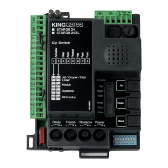
Backjump adjustment This procedure allows for adjusting or eliminating the backjump. It consists in inverting the gate movement at the end of the path to facilitate unlocking and to safeguard the mechanical system. On certain motors this is unnecessary, therefore the value is set to 1 by default. DEFAULT: Jet, Couper, Intro or Dynamos motors (see dip-switch 1 and 2 settings) backjump = value 1 Minimodus motors (see dip-switch 1 and 2 settings) = value 2... -
Page 4: Aux Output Programming
AUX output programming These programming sequences are not essential to the system’s operation, though they allow for setting the type (lock or courtesy light), work mode and output voltage (12VDC or 24VDC) of the devices connected to the AUX output. To interrupt the following programming sequences at any time, press the SET and RADIO buttons simultaneously or wait 10 seconds. -
Page 5: Selection Of Device Connected To "Aux" Output
13.2 - Selection of device connected to “AUX” output Default = electric lock This procedure allows for setting the “AUX” output for the operation as: ELECTRIC LOCK: the control unit closes the AUX contact (terminals 3-4) whenever a command is received. By default the contact is closed for 2 seconds (electric lock mode ). -
Page 6: Selection Of "Aux" Output Voltage
Paragraph 12.1 and connect a suitable relay (see paragraph 12). 13.4 - Selection of “AUX” output voltage (only for STARG8 24) Default = 12VDC The output voltage of the AUX contact can be set to 12VDC or 24VDC, depending on the connected lock or the available relay. -
Page 7: Safety Device Advanced Programming Sequences
Safety device advanced programming sequences These programming sequences are not essential to the system’s operation, but they allow for controlling the safety devices by activating the photo-test—when photocells are installed—or controlling the resistance when 8.2kOhm resistive edges are mounted. To interrupt the following programming sequences at any time, press the SET and RADIO buttons simultaneously or wait 10 seconds. -
Page 8: Selection Of The Outputs Linked To The Photo-Test
14.2 - Selection of the outputs linked to the photo-test Default = PHO1 and PHO2 contacts (terminals 5-6) With this procedure, it is possible to decide on which safety devices to carry out the photo-test. 1. SIMULTANEOUSLY PRESS THE SET, RADIO AND START BUTTONS FOR 3 SECONDS All the LEDs turn off... -
Page 9: Setting The Wired Commands
Setting the wired commands These programming sequences allow for locking wired commands, for managing the system solely with radio transmitters or for changing the operation of the wired commands to start and pedestrian. If, at the start of the following procedures, the “set”, “radio” and “start” LEDs flash, it means that the programming protec- tion has been activated –... -
Page 10: Activating/Deactivating Start And Pedestrian Lock
15.2 - Activating/deactivating start and pedestrian lock Default = wired start and start button on PCB activated. This programming sequence allows for locking the “start” / “ped” wired input and the start button on the control unit. This may be useful for controlling the automation exclusively via radio. -
Page 11: Resetting The Control Unit's Default Parameters
16.3 - Energy saving mode (only for STARG8 24) This feature cuts the power supply to the photocells when the control unit is on standby, therefore it decreases the power consumption. It is useful in case of battery power supply conditions. -
Page 12: Memory Management
The control devices (e.g.: receivers, spires or photocells connected to the Start contact) must be connected to terminal 8 “+VA”. If DIP-SWITCH 7 “fast” is put to ON, with the control unit open the accessories remain powered to retain the re-closing function. If you activate the power saving mode all the LEDs will turn off after 2 minutes of stand-by Memory management MEMO200... -
Page 13: Automatic Data Importing From External Memory
After this procedure, if the memory is left connected to the PCB, the external memory will continue to be updated. If instead no changes occur, such as the addition of transmitters or modifications to parameters, the memory can be removed. 17.2 - Automatic data importing from external memory This procedure allows for importing, from the external memory to the control unit, the transmitters and any settings activated through the... -
Page 14: Manual Data Importing From External Memory
17.3 - Manual data importing from external memory This procedure allows for importing transmitters from the external memory to the control unit, by selecting the desired function and the rele- vant button associated with it. Example: an external memory containing programmed remote controls to be imported, by linking button 3 to the pedestrian opening function. - Page 16 Dati dell’installatore / Installer details Azienda / Company Timbro / Stamp Località / Address Provincia / Province Recapito telefonico / Tel. Referente / Contact person Dati del costruttore / Manufacturer's details King Gates S.r.l. Phone +39.0434.737082 Fax +39.0434.786031 info@king-gates.com www.king-gates.com...
Need help?
Do you have a question about the STARG8 24 and is the answer not in the manual?
Questions and answers