Advertisement
Advertisement
Table of Contents

Summary of Contents for King gates Couper 24
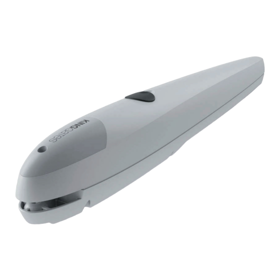
- Page 1 Couper Motori gear for swing gates MADE IN ITALY INSTRUCTION MANUAL...
-
Page 2: General Description
1 - GENERAL DESCRIPTION 1A - WARNINGS Unfulfilment of the below listed direction will release the KING gates srl, from any responsibility for damage caused to people or things. -Do not modify the product in any part. -To optimize the functioning of the automation, King gates accessories only .-Installing, testing and first functioning have to observe the laws in force. -
Page 3: Typical System
2 - TYPICAL SYSTEM 2A - TYPICAL SYSTEM A - Gear-motor B - Control unit C - Flash-light with antenna D - Photocell in closing E - Photocell in opening F - Key selector G - Warning sign H - Stop locks 2B - TYPICAL CONNECTION AND CABLE SECTION RG58 (dist max 5m) 0,5mm2 (dist max 50m) - Page 4 2C - DIMENSIONS Front Rear braket braket 130mm 130mm 40mm 80mm Rear vertical 80mm braket 130mm...
- Page 5 3 - BRACKETS INSTALLATION SCHEME 3A - HOW TO USE A GRAPH Measure "E", and draw a horizontal line in graph at the read measure. Choose a point on the drawn line, considering the desired opening angle, suitable to the column.
- Page 6 3C - GRAPH 90° 100° 110° A (mm) If the installation measures are not properly followed, the atomation could not work correctly. For example: - Cyclical trends, and sudden accelerations - Noise of the motor - Limited opening degree or absent opening (in case of motor counter-lever fixed)
-
Page 7: Installation
4 - INSTALLATION 4A - INTRODCTION Read the instructions with care before installing the product. The producer disclaims all responsibility for any damage or bad functioning caused by non-observance of the instructions or bad connection that may result in poor safety and functioning of the gear-motor. -
Page 8: Manual Control
5 - MANUAL CONTROL 5A - INTRODUCTION Before operating the manual release disconnect the power Manual control has been thought for manual opening of the gate in case of power-cut or motor breakdown. 5B - RELEASE INSTRUCTION (see pic.4). - Open the manual release cover - Insert the key in the cylinder and turn it of 90°... -
Page 9: Electrical Connection
6 - ELECTRICAL CONNECTION 6A - CONNECTION TO THE POWER STATION To connect the gear motor to the control unit, proceed as follows: 01. Remove the lid of the gear motor as shown in fig. 12; 02. Slacken the gearmotor cable clamp, thread the connecting cable through the hole and connect the three electric wires 03.


Need help?
Do you have a question about the Couper 24 and is the answer not in the manual?
Questions and answers