Lippert Components Ground Control 3.0 User Manual
Hide thumbs
Also See for Ground Control 3.0:
- User manual ,
- Service manual (28 pages) ,
- Owner's manual (24 pages)
Table of Contents
Advertisement
Table Of Contents
Introduction . . . . . . . . . . . . . . . . . . . . . . . . . . . . . . . . . . . 2
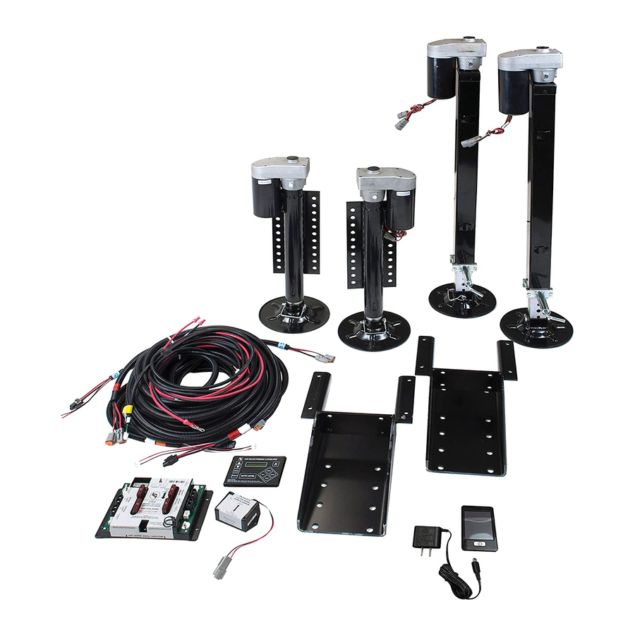
Parts List. . . . . . . . . . . . . . . . . . . . . . . . . . . . . . . . . . . . . . 2
6-Point System . . . . . . . . . . . . . . . . . . . . . . . . . . . . . . . . . 3
6-Point Application
Preparation . . . . . . . . . . . . . . . . . . . . . . . . . . . . . . . . . . . . 4
Installation . . . . . . . . . . . . . . . . . . . . . . . . . . . . . . . . . . . . 5
lci1.com
3.0 4-Point or
®
(574) 537-8900
Ground Control® 3.0
Aftermarket Manual
Ground Control
Aftermarket
Manual
Installation - Controller . . . . . . . . . . . . . . . . . . . . . . . . . . 9
Installation - Touch Pad. . . . . . . . . . . . . . . . . . . . . . . . . 10
Wiring Diagram - 4 Point . . . . . . . . . . . . . . . . . . . . . . . 11
Wiring Diagram - 6 Point . . . . . . . . . . . . . . . . . . . . . . . 12
System and Safety Information . . . . . . . . . . . . . . . . . . 13
Prior to Operation . . . . . . . . . . . . . . . . . . . . . . . . . . . . . 13
Touch Pad Diagram . . . . . . . . . . . . . . . . . . . . . . . . . . . . 13
Basic Operation . . . . . . . . . . . . . . . . . . . . . . . . . . . . . . . 14
Unhitching from a Tow Vehicle. . . . . . . . . . . . . . . . . . . 14
Auto Level . . . . . . . . . . . . . . . . . . . . . . . . . . . . . . . . . . . . 15
2
2
Auto Level Sequence. . . . . . . . . . . . . . . . . . . . . . . . . . . 15
Hitch Recognition . . . . . . . . . . . . . . . . . . . . . . . . . . . . . 16
Troubleshooting . . . . . . . . . . . . . . . . . . . . . . . . . . . . . . . 16
3
3
System Settings . . . . . . . . . . . . . . . . . . . . . . . . . . . . . . . 19
4
Configuring the Remote . . . . . . . . . . . . . . . . . . . . . . . . 19
Resetting the Remote . . . . . . . . . . . . . . . . . . . . . . . . . . 21
5
Configure Remote to Touch Pad . . . . . . . . . . . . . . . . . 22
5
Preventative Maintenance. . . . . . . . . . . . . . . . . . . . . . . 23
6
Notes . . . . . . . . . . . . . . . . . . . . . . . . . . . . . . . . . . . . . . . . 23
7
1
CCD-0001307
3.0
®
16
17
18
19
Rev: 04.19.18
Advertisement
Table of Contents

Related Manuals for Lippert Components Ground Control 3.0


Summary of Contents for Lippert Components Ground Control 3.0
-
Page 1: Table Of Contents
Ground Control® 3.0 Aftermarket Manual Ground Control ® Aftermarket Manual Installation - Controller ......9 Installation - Touch Pad. -
Page 2: Introduction
Ground Control® 3.0 Aftermarket Manual Introduction Ground Control® 3.0 is a revolutionary electric leveling system for towable RVs. Its Hitch Recognition Memory Function remembers where the Auto Level sequence was started, saving time during hook-up. Fully Automatic Electric Leveling System LCI has taken its Ground Control®... -
Page 3: Determining Use Of Ground Control
Ground Control® 3.0 Aftermarket Manual Determining Use of Ground Control 3.0 4-Point or 6-Point System ® 4-Point Application If the GVWR of the trailer is less than 15,500 lbs. and the distance between the center of the landing gear foot and the center of the rear jack foot will be less than 20 feet (Fig. -
Page 4: Preparation
Ground Control® 3.0 Aftermarket Manual Preparation 1. Remove all loose items from the front storage compartments of the trailer. 2. Support the trailer at all four corners with jack stands (or other adequate supports). 3. Remove the underbelly from the trailer and set aside. Determining the Mounting Position of the Jack Brackets and Components 1. -
Page 5: Installation
Ground Control® 3.0 Aftermarket Manual Installation Measuring Departure and Approach Angle To measure departure and approach angles, run a string line from the meeting point of the tire and the ground up at an angle to the lowest point on the front or rear of the trailer. These string lines are shown as dotted lines (Fig. 5). Fig.5 Ground Approach Angle String Line... -
Page 6: Rear And Middle Jacks
Ground Control® 3.0 Aftermarket Manual Rear and Middle Jacks 1. Determine position and ground clearance requirements for Main Frame Rail the rear and middle jacks. The rear jack brackets should be mounted approximately 12” behind the rear tire and be aligned with each other. -
Page 7: Rear Sensor
Ground Control® 3.0 Aftermarket Manual 2. Attach the rear sensor (Fig. 12B) to the mounting plate Rear Sensor (Fig. 12C) using two #8 - 18 x 1” self-drilling screws (Fig. Note: The rear sensor (Fig. 10) MUST be installed on a 12A). - Page 8 Ground Control® 3.0 Aftermarket Manual 3. Attach the rear sensor (Fig. 13C) and the mounting plate (Fig. 4. Connect the rear sensor harness to the connector on the rear 13B) to the crossmember (Fig. 13D) using two #8 - 18 x 1” sensor (Fig.
-
Page 9: Installation - Controller
Ground Control® 3.0 Aftermarket Manual Installation - Controller 1. Measure to the center of the trailer from inside the Note: Prior to starting this portion of the installation, double compartment where the controller will be placed, and mark check that all of the harnesses are properly and securely the center point on the ceiling. -
Page 10: Installation - Touch Pad
Ground Control® 3.0 Aftermarket Manual Installation - Touch Pad 1. Determine where to mount the touch pad. The touch pad should be mounted in a compartment on the side of the trailer so the operator will have a view of the hitch pin while using the touch pad. -
Page 11: Wiring Diagram - 4 Point
Ground Control® 3.0 Aftermarket Manual Wiring Diagram - 4 Point LCD Touch Pad Rear Sensor Hall Effect Hall Effect Landing Landing Gear Gear Touch Pad Rear Sensor Harness Harness 4 Point Controller Recommended Battery 50 Amp Breaker (not included) Hall Hall Effect Effect... -
Page 12: Wiring Diagram - 6 Point
Ground Control® 3.0 Aftermarket Manual Wiring Diagram - 6 Point LCD Touch Pad Hall Effect Hall Effect Landing Landing Gear Gear Rear Sensor Rear Sensor Harness Touch Pad Harness 6 Point Controller Hall Hall Effect Effect Jack Jack Recommended 50 Amp Breaker (not included) Battery... -
Page 13: System And Safety Information
Ground Control® 3.0 Aftermarket Manual System and Safety Information Prior to Operation The leveling system should only be operated under the following conditions: 1. The trailer is parked on a reasonably level surface. Failure to act in accordance with the following may 2. -
Page 14: Basic Operation
Ground Control® 3.0 Aftermarket Manual Basic Jack Operation Unhitching from a Tow Vehicle Landing gear (front jacks) can be operated any time the Note: Prior to unhitching from the tow vehicle, ensure the trailer system is “ON”. By pushing the “FRONT” button (Fig. 22G), is parked on a level surface and be sure to chock the tires of both front jacks can be extended. -
Page 15: Auto Level
Ground Control® 3.0 Aftermarket Manual Auto Level 1. After unhitching from tow vehicle and parking the tow vehicle at a safe distance away from the trailer, press the “ON/OFF” button (Fig. 22K) and then press “AUTO LEVEL” (Fig. 22F). Note: Once the automatic leveling cycle has been started, it is important that there is no movement in the trailer until the trailer has completed the leveling process. -
Page 16: Hitch Recognition
Ground Control® 3.0 Aftermarket Manual Hitch Recognition Manual Override Note: For ease of manual override it is recommended to unplug 1. Turn on the touch pad. the power harness to the motor prior to performing the manual 2. Push the “UP” arrow (Fig. 26A) to scroll to “Auto Reconnect” override procedure. -
Page 17: Special Jack Error Codes
Ground Control® 3.0 Aftermarket Manual Bottom of Jack Motor Override Special Jack Error Codes To clear one of the error codes listed below: Resources Required: 3/8” drive ratchet and extension, 5/16” socket 1. Correct or otherwise repair the issue (see the table below). 1. -
Page 18: Touch Pad
Ground Control® 3.0 Aftermarket Manual Touch Pad Note: To clear an error from the touch pad, repair or otherwise correct the issue, then press “ENTER”. If the error is still present, the message will be displayed again. LCD Message What's Happening? What Should Be Done? Controller not properly secured. -
Page 19: System Settings
Ground Control® 3.0 Aftermarket Manual System Settings Configuring the Remote Zero Point Calibration 1. Turn the remote on by pressing and releasing the large silver button at the bottom of the remote (Fig. 36A). If the remote The “Zero Point” is the programmed point that the trailer will return has never been configured, it will display the “Config”... - Page 20 Ground Control® 3.0 Aftermarket Manual 6. Press the select button at each screen. Without an LCI Multifunction Wireless system installed on the trailer, no other functions will be able to be programmed on the remote. 7. If the remote was purchased before 7/13 refer to Step A, if it was purchased after 7/13 refer to Step B.
-
Page 21: Resetting The Remote
Ground Control® 3.0 Aftermarket Manual Resetting the Remote 10. Enter a pin to be the security code for accessing the remote Once the remote has been configured it can be reconfigured (Fig. 43). in the event of a function changing or a new security pin is required. -
Page 22: Configure Remote To Touch Pad
Ground Control® 3.0 Aftermarket Manual Configure Remote to Touch Pad 1. Enter the Leveler app on the LINC Remote. 2. Turn the remote on by pressing and releasing the large silver button at the bottom of the remote. 3. Press the “OK” button on the touch screen to access the Function Menu (Fig. -
Page 23: Preventative Maintenance
Ground Control® 3.0 Aftermarket Manual Preventative Maintenance Notes 1. For optimum performance, the system requires full battery current and voltage. The battery MUST be maintained at full capacity. 2. Check the terminals and other connections at the battery, the controller, and the jacks for corrosion, and loose or damaged connections. - Page 24 Aftermarket Manual Notes Manual information may be distributed as a complete document only, unless Lippert Components provides explicit consent to distribute individual parts. All manual information is subject to change without notice. Revised editions will be available for free download at www.
Need help?
Do you have a question about the Ground Control 3.0 and is the answer not in the manual?
Questions and answers
What is the dimension of the leveling feet?
The leveling feet for the Lippert Components Ground Control 3.0 have a 9-inch diameter foot plate.
This answer is automatically generated