Lippert Components Ground Control 3.0 Manual
- Service manual (28 pages) ,
- Owner's manual (24 pages) ,
- User manual (24 pages)
Advertisement
- 1 System Information
- 2 Safety Information
- 3 Touch Panel Diagram - Auto Leveling Control Touch Panel
- 4 Operation - Auto Leveling Control Touch Panel
- 5 Touch Panel Diagram - OneControl Touch Panel
- 6 Operation - OneControl Touch Panel
- 7 Touch Panel Diagram - OneControlApp From MyRV
- 8 Operation - OneControl App
- 9 Touch Panel Diagram - Linc Remote Control - Optional
- 10 Troubleshooting
- 11 Preventive Maintenance
- 12 GROUND CONTROL 3.0 4 POINT ASSEMBLY
- 13 GROUND CONTROL 3.0 6 POINT ASSEMBLY
- 14 GROUND CONTROL 3.0 COMPONENTS
- 15 Videos
- 16 Documents / Resources
System Information
Ground Control 3.0 is an automatic leveling system for 5th wheel applications. The system utilizes one main control board and a separate waterproof remote level sensor to measure and manage level point, and can be operated from several user interface devices, including:
- Auto Leveling Control Touch Panel - Mounted outside the trailer within view of the hitch.
- MyRV® OneControl™ Touch Panel (OCTP) - Mounted on a wall inside the living space of the trailer or in a trailer compartment.
- MyRV® OneControl™ Leveling App - The app is available on iTunes® for iPhone® and iPad® and also on Google Play™ for Android™ users. iTunes®, iPhone® and iPad® are registered trademarks of Apple Inc. Google Play™ and Android™ are trademarks of Google Inc.
- Linc® Remote Control - Optional.
Safety Information
Be sure to park the trailer on solid, level ground. Ensure all jack landing locations are cleared of debris and obstructions and also free of depressions. People and pets should be clear of trailer while operating the leveling system. Ensure the battery of the trailer is fully charged or that the trailer is plugged into shore power prior to attempting to operate the system. Ground Control 3.0 requires a minimum of 12.75V DC from the battery for proper operation.

Lippert Components Inc. recommends that a trained professional be employed to change the tires on the trailer. Ensure that the trailer is properly supported with jack stands or other adequate devices under the frame of the trailer prior to commencing any service or repair procedure. Any attempts to change the tires or perform other service while trailer is supported solely by the Ground Control 3.0 jacks could result in death, serious injury, trailer or property damage.
Touch Panel Diagram - Auto Leveling Control Touch Panel

Fig. 1
| Callout | Description | |
| A | Red/Green LED - Indicates the status of the system. | |
| B | Up Arrow - Extends front jacks (landing gear). | To turn on the touch panel, press the Up and Down arrow buttons at the same time. |
| C | Down Arrow - Retracts front jacks (landing gear). | |
| D | Auto Level Button - Places leveling system into auto level mode. | |
| E | Hitch Height Button - Initiates the Hitch Recognition feature. | |
| F | Retract All Button - Places leveling system into full retract mode. | |
Operation - Auto Leveling Control Touch Panel
Unhitching Instructions
NOTE: Prior to unhitching from the tow vehicle, ensure the trailer is parked on a level surface and chock the tires of the trailer.
- Extend the inner legs of both front jacks (landing gear) to within 4-5" of the ground by pulling on the quickrelease pins.
- To turn on the touch panel, press both "UP" and "DOWN" arrows (Fig. 1B and Fig. 1C) at the same time. The green indicator LED (Fig. 1A) will turn on.
NOTE: The touch panel will remain on as long as the user is pressing buttons. It will time out after approximately 7 minutes without use. - Press the "UP" arrow (Fig. 1B) to extend the front jacks and lift the front of the trailer to take the weight of the trailer off of the hitch.
- Uncouple the trailer connection on the tow vehicle.
- Pull the tow vehicle away and park at a safe distance.
Auto Level
- After unhitching from the tow vehicle and parking the vehicle at a safe distance away from the trailer. Press both "UP" and "DOWN" arrows (Fig. 1B and Fig. 1C) at the same time if the green indicator LED is not on. Press "AUTO LEVEL" (Fig. 1D).
NOTE: Once the automatic leveling cycle has been started, it is important that there is no movement in the trailer until the leveling process is complete. Failure to remain still during the leveling cycle could have an effect on the performance of the leveling system.
Auto Level Sequence
- When Auto Level Sequence begins, the front of the trailer will seek a position near a level state.
- Rear jacks will be grounded.
- A side-to-side leveling sequence will occur.
NOTE: At this point on the 6 point system, the 2 middle jacks will be grounded to stabilize the trailer. These 2 jacks do not level the trailer. - Each jack will perform a final grounding touch.
NOTE: If the AUTO LEVEL sequence does not perform as described above, locate the OneControl Touch Panel inside the trailer or use the OneControl App to place the system in manual mode. Test that the jacks operate correctly by pushing their corresponding buttons on the OneControl Touch Panel or app; e.g., "FRONT" button operates only the front jacks, etc. (See "Operation - OneControl Touch Panel" or "Operation - OneControl App" in this manual).
Hitch Recognition
- To turn on the touch panel, press both "UP" and "DOWN" arrows (Fig. 1B and Fig. 1C) at the same time. The green indicator LED (Fig. 1A) will turn on.
- Press "HITCH HEIGHT" (Fig. 1E). The rear jacks will retract.
- The front of the trailer will raise to the height where the auto level sequence was started.
NOTE: If the front of the trailer was below level when the Auto Level process was initiated, the hitch recognition feature will retract the rear jacks but will not retract the front jacks to lower the trailer to the initial hitch height. This feature helps prevent injury and/or damage to anything underneath the trailer. - Connect tow vehicle and make sure trailer and hitch are connected and locked.
- Press "RETRACT ALL." (Fig. 1F). System will immediately retract all jacks.
- Use the quick release pins on the landing gear to manually return the inner jack leg to the fully retracted position.
Touch Panel Diagram - OneControl Touch Panel

Fig. 2 - Leveling Standard Mode
| Callout | Description |
| A | Jack Buttons - Select front, rear, right and left jacks to be operated depending on mode. Jacks available to be operated will be highlighted in blue. The front jacks can be extended/retracted in Standard Mode. Rear jacks can only be retracted from this mode. In Manual Mode (Fig. 3), all jacks are available to be operated. |
| B | Up and Down Arrows - Scrolls through options on screen. |
| C | Info - Displays system information, e.g. angle, jack stroke or software version. |
| D | Connected Icon - Press 6 times to program zero point/ wireless configurations. |
| E | Home Icon - Returns screen to home page. |
| F | Auto Retract - Enters Auto Retract mode. Choose to retract "All Jacks" or "Rear Jacks." |
| G | Manual Mode - Enters Manual Mode to manually operate jacks. |
| H | Enter - Push to select various modes. |
| I | Retract - Retracts jacks in several modes. Jacks available will be highlighted in blue. |
| J | Extend - Extends jacks in several modes. Jacks available will be highlighted in blue. |
| K | Reset - Resets to factory default. |
| L | Power Button - Turns touch panel on and off. |
| M | Auto Level - Starts the Auto Level sequence. |
| N | Auto Hitch - Returns trailer to previous hitch height for reconnecting to tow vehicle. |
Operation - OneControl Touch Panel
Standard Mode and Menu
To reach Standard Mode (Fig. 2) for leveling:
- Power on the OneControl Touch Panel (Fig. 2L).
- Press "MyRV Control Panel" on the main screen.
- Press the "Leveler" icon.
- The screen will show the system menu (Fig. 2) for Standard Mode. The front jacks can be extended/ retracted in Standard Mode. Rear jacks can only be retracted from this mode.
Basic Jack Operation
While in Standard Mode:
- Press "RETRACT" (Fig. 2I) or "EXTEND" (Fig. 2J) and "FRONT" (Fig. 2A) to retract or extend front jacks.
- Press "RETRACT" and "REAR" to retract rear jacks.
- Press the "AUTO LEVEL" (Fig. 2M) button to start the auto leveling sequence.
- Press the "AUTO HITCH" (Fig. 2N) button to start the hitch recognition sequence when reconnecting to the tow vehicle.
- Use the "UP" or "DOWN" arrow (Fig. 2B) buttons to cycle through the menu screen options:
- Info: Scroll to "INFO" (Fig. 2C) and press "ENTER" (Fig. 2H) button to display system information, e.g., angle, jack stroke or software version.
- Auto Retract: Scroll to "AUTO RETRACT" (Fig. 2F) and press the "ENTER" button. Choose either "ALL JACKS" or "REAR JACKS." Press the "ENTER" button again to start the "Auto Retract" sequence.
- Manual Mode: Scroll to "MANUAL MODE" (Fig. 2G) and press "ENTER" button to start Manual Level operation.
NOTE: Upon entering Manual Mode, a tutorial on operating the jacks will appear on the screen. Press "OK" to clear the tutorial. To delete the tutorial, click the "Don't show this again" box in the bottom right of the screen.- Press "EXTEND" (Fig. 3F) or "RETRACT" (Fig. 3E) and "FRONT" (Fig. 3B) to operate front jacks.
- Press "EXTEND" or "RETRACT" and "REAR" (Fig. 3D) to operate rear jacks.
- Press "EXTEND" or "RETRACT" and "RIGHT" (Fig. 3C) to operate right jacks.
- Press "EXTEND" or "RETRACT" and "LEFT" ( Fig. 3A) to operate left jacks.
NOTE: To operate jacks individually, press "EXTEND" or "RETRACT" then press the "LEFT" (Fig. 3A) or "RIGHT" (Fig. 3C) button while simultaneously pressing the "FRONT" (Fig. 3B) or "REAR" button (Fig. 3D), depending on which jack needs to be operated.
NOTE: If the rear jacks will not operate individually using the method described above, but they operate properly when Auto Level is performed, the Twist Prevention Protection system has locked out the operation to prevent damage to the frame of the trailer.

Fig. 3
Unhitching Instructions
NOTE: Prior to unhitching from the tow vehicle, ensure the trailer is parked on a level surface and chock the tires of the trailer.
- Extend the inner legs of both front jacks (landing gear) to within 4-5" of the ground by pulling on the quickrelease pins.
- Push touch panel "ON/OFF" (Fig. 2L) to turn system on.
- Press "MyRV Control Panel" on the main screen.
- Press the "Leveler" icon.
- The screen will show the system menu (Fig. 2) for Standard Mode. Push "EXTEND" (Fig. 2J) and "FRONT" button (Fig. 2A) to extend front jacks and lift front of the trailer to take the weight of the trailer off of the hitch.
- Uncouple the trailer connection on the tow vehicle.
- Pull the tow vehicle away and park at a safe distance.
Auto Level
- After unhitching from the tow vehicle and parking the vehicle a safe distance away from the trailer, press the "ON/OFF" button (Fig. 2L) if the OneControl Touch Panel is not on and then press "AUTO LEVEL" (Fig. 2M).
NOTE: Once the automatic leveling cycle has been started, it is important that there is no movement in the trailer until the leveling process is complete. Failure to remain still during the leveling cycle could have an effect on the performance of the leveling system.
Auto Level Sequence
- When Auto Level Sequence begins, the front of the trailer will seek a position near a level state.
- Rear jacks will be grounded.
- A side-to-side leveling sequence will occur.
NOTE: At this point on the 6 point system, the 2 middle jacks will be grounded to stabilize the trailer. These 2 jacks do not level the trailer. - Each jack will perform a final grounding touch.
NOTE: If the AUTO LEVEL sequence does not perform as described above, locate the OneControl Touch Panel inside the trailer or use the OneControl App to place the system in manual mode. Test that the jacks operate correctly by pushing their corresponding buttons on the OneControl Touch Panel or App; e.g., "FRONT" button operates only the front jacks, etc. (See "Operation - OneControl Touch Panel" or "Operation - OneControl App" in this manual).
Hitch Recognition
- Push touch panel "ON/OFF" (Fig. 2L) to turn system on.
- Press "MyRV Control Panel" on the main screen.
- Press the "Leveler" icon.
- The screen will show the system menu (Fig. 2) for Standard Mode.
- Press "AUTO HITCH" (Fig. 2N). Rear jacks will retract.
- The front of the trailer will raise to the height where the auto level sequence was started.
NOTE: If the front of the trailer was below level when the Auto Level process was initiated, the hitch recognition feature will retract the rear jacks but will not retract the front jacks to lower the trailer to the initial hitch height. This feature helps prevent injury and/or damage to anything underneath the trailer. - Connect tow vehicle and make sure trailer and hitch are connected and locked.
- On the Standard Mode screen (Fig. 2) use the "UP" and "DOWN" arrows (Fig. 2B) to scroll to "AUTO RETRACT" (Fig. 2F). Press "ENTER."
- Choose "ALL JACKS." Press "ENTER." System will immediately retract all jacks.
- Use the quick release pins on the landing gear to manually return the inner jack leg to the fully retracted position.
Touch Panel Diagram - OneControlApp From MyRV
NOTE: The OneControl Leveling App is available on iTunes® for iPhone® and iPad® and also on Google Play™ for Android™ users.

Fig. 4 - Leveling Standard Mode
| Callout | Description |
| A | Jack Buttons - Select front, rear, right and left jacks to be operated depending on mode. Jacks available to be operated will be highlighted in blue. The front jacks can be extended/retracted in Standard Mode. Rear jacks can only be retracted from this mode. In Manual Mode (Fig. 6), all jacks are available to be operated. |
| B | Enter - Push to activate various modes. |
| C | Info - Displays system information, e.g., angle, jack stroke, software version. |
| D | Auto Retract - Enters Auto Retract mode. Choose to retract "All Jacks" or "Rear Jacks." |
| E | Manual Mode - Enters Manual Mode to manually operate jacks. |
| F | Home Icon - Returns screen to home page. |
| G | Up and Down Arrows - Scroll through options on screen. |
| H | Retract - Retracts jacks in several modes. Jacks available will be highlighted in blue. |
| I | Extend - Extends jacks in several modes. Jacks available will be highlighted in blue. |
| J | Auto Level - Starts the Auto Level sequence. |
| K | Auto Hitch - Returns trailer to previous hitch height for reconnecting to tow vehicle. |
Operation - OneControl App
Accessing the OneControl App
- Ensure there is power to the trailer's wireless network.
- Navigate to the device's (smart phone, tablet, etc.) wifi settings. Turn wireless feature on and connect to the myRV wireless network.
NOTE: If this is the first time connecting to the myRV wireless network, a password will be required. The password is located on the trailer's wifi hub (Fig. 5).

Fig. 5
- Open the OneControl application on the compatible device.
NOTE: If the device states "Unresolved Network Connection," retry connecting to the myRV wireless network and/or wait for the connection to resolve and display "Connected" under the myRV wireless connection. - The application will request the user "Agree" to an end user license agreement, create a PIN and "Re-enter PIN to confirm."
- The OneControl app will now display all functions. Choose "Leveler."

Standard Mode and Menu
Standard Mode is the mode launched when the OneControl app "Leveler" function is powered up. The screen will show the system menu (Fig. 4). The front jacks can be extended/retracted in Standard Mode. Rear jacks can only be retracted from this mode.
Basic Jack Operation
While in Standard Mode:
- Press "RETRACT" (Fig. 4H) or "EXTEND" (Fig. 4I) and "FRONT" (Fig. 4A) to extend or retract front jacks.
- Press "RETRACT" and "REAR" (Fig. 4) to retract rear jacks.
- Press the "AUTO LEVEL" (Fig. 4J) button to start the leveling sequence.
- Press the "AUTO HITCH" (Fig. 4K) button to start the hitch recognition sequence when reconnecting to the tow vehicle.
- Use the "UP" or "DOWN" arrow buttons (Fig. 4G) to cycle through the menu options:
- Info: Scroll to "INFO" (Fig. 4C) and press "ENTER" button to display system information, e.g., angle, jack stroke or software version.
- Auto Retract: Scroll to "AUTO RETRACT" (Fig. 4D) and press the "ENTER" button. Choose either "ALL JACKS" or "REAR JACKS." Press the "ENTER" button again to start the "Auto Retract" sequence.
- Manual Mode: Scroll to "MANUAL MODE" (Fig. 4E) and press "ENTER" button to start Manual Level operation.
- Press "EXTEND" (Fig. 6F) or "RETRACT" (Fig. 6E) and "FRONT" (Fig. 6B) to operate front jacks.
- Press "EXTEND" or "RETRACT" and "REAR" to operate rear jacks.
- Press "EXTEND" or "RETRACT" and "RIGHT" to operate right jacks.
- Press "EXTEND" or "RETRACT" and "LEFT" to operate left jacks.
NOTE: To operate jacks individually, press "EXTEND" or "RETRACT" then press the "LEFT" (Fig. 6A) or "RIGHT" (Fig. 6C) button while simultaneously pressing the "FRONT" or "REAR" button (Fig. 6B and 6D), depending on which jack needs to be operated.

Fig. 6 - Manual Mode
NOTE: If the rear jacks will not operate individually using the method described above, but they operate properly when Auto Level is performed, the Twist Prevention Protection system has locked out the operation to prevent damage to the frame of the trailer.
Unhitching Instructions
NOTE: Prior to unhitching from the tow vehicle, ensure trailer is parked on a level surface and chock the tires of the trailer.
- Extend the inner legs of both front jacks (landing gear)to within 4-5" of the ground by pulling on the quickrelease pins.
- Push "Extend" (Fig. 4I) and "FRONT" buttons (Fig. 4) to extend front jacks and lift front of trailer to take the weight of the trailer off of the hitch.
- Uncouple the trailer connection on the tow vehicle.
- Pull tow vehicle away and park at a safe distance.
Auto Level
- After unhitching from the tow vehicle and parking the vehicle at a safe distance away from the trailer, open the OneControl App and then press "AUTO LEVEL" (Fig. 4J).
NOTE: Once the automatic leveling cycle has been started, it is important that there is no movement in the trailer until the trailer has completed the leveling process. Failure to remain still during the leveling cycle could have an effect on the performance of the leveling system.
Auto Level Sequence
- When Auto Level Sequence begins, the front of the trailer will seek a position near a level state.
- Rear jacks will be grounded.
- A side-to-side leveling sequence will occur.
NOTE: At this point on the 6 point system, the 2 middle jacks will be grounded to stabilize the trailer. These 2 jacks do not level the trailer. - Each jack will perform a final grounding touch.
NOTE: If the AUTO LEVEL sequence does not perform as described above, locate the OneControl Touch Panel inside the trailer or use the OneControl App to place the system in manual mode. Test that the jacks operate correctly by pushing their corresponding buttons on the OneControl Touch Panel or App; e.g., "FRONT" button operates only the front jacks, etc. (See "Operation - OneControl Touch Panel" or "Operation - OneControl App" in this manual).
Hitch Recognition
- Open the OneControl App.
- Press the "Leveler" icon.
- The screen will show the system menu (Fig. 4) for Standard Mode.
- Press "AUTO HITCH" (Fig. 4K). Rear jacks will retract.
- The front of the trailer will raise to the height where the auto level sequence was started.
NOTE: If the front of the trailer was below level when the Auto Level process was initiated, the hitch recognition feature will retract the rear jacks but will not retract the front jacks to lower the trailer to the initial hitch height. This feature helps prevent injury and/or damage to anything underneath the trailer. - Connect tow vehicle and make sure trailer and hitch are connected and locked.
- On the Standard Mode screen (Fig. 4) use the "UP" and "DOWN" arrows (Fig. 4G) to scroll to "AUTO RETRACT" (Fig. 4D). Press "ENTER."
- Choose "ALL JACKS." Press "ENTER." System will immediately retract all jacks.
- Use the quick release pins on the landing gear to manually return the inner jack leg to the fully retracted position.
Touch Panel Diagram - Linc Remote Control - Optional

Fig. 7
| Callout | Description |
| A | Retract - Retracts front jacks and rear jacks. |
| B | Front Arrow - Operates front jacks. |
| C | Left Arrow - (See Note below) |
| D | Help - Provides contact information for LCI. |
| E | Extend - Extends front jacks. (See Note below) |
| F | Right Arrow - (See Note below) |
| G | Rear Arrow - Retracts rear jacks. (See Note below) |
| H | Auto Level- Initiates Auto Level sequence. |
| I | Power Button - Turns remote control on and off. |
NOTE: When the OneControl Touch Panel inside the trailer is placed in Manual Mode, the Linc remote will operate the jacks in a similar fashion as the OneControl, with the exception of operating individual jacks. (See "Operation - OneControl Touch Panel.)
Configuring Linc Remote to Sync to The One Control Touch Panel
- Turn on the Linc™ remote control (Fig. 7I) and enter a PIN.
- Choose "Leveler" from the menu screen.
- Turn on the OneControl Touch Panel (Fig. 2L).
- On the OneControl Touch Panel, press the "CONNECTED" icon at the top of the screen (Fig. 8A) quickly 6 times. Wait a few seconds until the gear icon with "OPTIONS" appears (Fig. 9A).
- Press the gear icon with "OPTIONS" (Fig. 9A).
- Use the "UP" and "DOWN" arrows (Fig. 9B) to scroll to "WIRELESS CONFIG" (Fig. 10).
- Press "ENTER" (Fig. 10A). The screen will display "Wireless Configuration Press any Linc button to Sync" (Fig. 11).
- Press any button in "Leveler" mode on the Linc Remote Control (Fig 7).
- Pressing "ABORT" on the OneControl Touch Panel (Fig. 11A) will cancel configuration sequence.

Fig. 8

Fig. 9

Fig. 10

Fig. 11
Basic Jack Operation
- Press "EXTEND" ( Fig. 7E) or "RETRACT" (Fig. 7A). Press "FRONT" arrow (Fig. 7B) to operate front jacks.
- Press "RETRACT". Press "REAR" arrow (Fig. 7G) to operate rear jacks.
- Press "AUTO LEVEL" (Fig. 7H) to start auto level sequence.
- If the OneControl Touch Panel is in manual mode press, "EXTEND" (Fig. 7E) or "RETRACT"(Fig. 7A). Press "LEFT" (Fig. 7C), "RIGHT" (Fig. 7F) or "REAR" (Fig. 7G) arrow to operate left, right or rear jacks.
Unhitching Instructions
NOTE: Prior to unhitching from the tow vehicle, ensure the trailer is parked on a level surface and chock the tires of the trailer.
- Extend the inner legs of both front jacks (landing gear) to within 4-5" of the ground by pulling on the quickrelease pins.
- Turn the Linc remote on (Fig. 7I) and enter a PIN code to turn system on.
- Press the "LEVELER" button.
- Press "EXTEND" (Fig. 7E) and "FRONT" arrow (Fig. 7B) to extend front jacks and lift the front of trailer to take the weight of the trailer off of the hitch.
- Uncouple the trailer connection on the tow vehicle.
- Pull tow vehicle away and park at a safe distance.
Auto Level
- After unhitching from the tow vehicle and parking the vehicle a safe distance away from the trailer, press the "ON/OFF" button (Fig. 7I) on the Linc remote if the Linc is not on.
- Enter a PIN.
- Choose the "LEVELER" option.
- Press "AUTO LEVEL" (Fig. 7H).
NOTE: Once the automatic leveling cycle has been started, it is important that there is no movement in the trailer until the trailer has completed the leveling process. Failure to remain still during the leveling cycle could have an effect on the performance of the leveling system.
Auto Level Sequence
- When Auto Level Sequence begins, the front of the trailer will seek a position near a level state.
- Rear jacks will be grounded.
- A side-to-side leveling sequence will occur.
NOTE: At this point on the 6 point system, the 2 middle jacks will be grounded to stabilize the trailer. These 2 jacks do not level the trailer. - Each jack will perform a final grounding touch.
NOTE: If the AUTO LEVEL sequence does not perform as described above, locate the OneControl Touch Panel inside the trailer or use the OneControl App to place the system in manual mode. Test that the jacks operate correctly by pushing their corresponding buttons on the OneControl Touch Panel or App; e.g., "FRONT" button operates only the front jacks, etc. (See "Operation - OneControl Touch Panel" or "Operation - OneControl App" in this manual).
NOTE: There is no Hitch Recognition sequence programmed for the Linc remote.
Troubleshooting
Red/Green LED Indicator on Auto Leveling Control Touch Panel
| What Is Happening? | Why? |
| Off | Touch panel is locked. |
| Solid Green | Touch panel is active. |
| Blinking Green | Jacks are moving. |
| Solid Red | Low battery. |
| Blinking Red | Error - Refer to OneControl Touch Panel screen or the Leveling App for the specific error, then consult the Troubleshooting section of this manual to clear the error. |
OneControl Touch Panel Error Codes
NOTE: Faults can only be cleared via the OneControl Touch Panel or OneControl Leveling App through MyRV®. The only exception is when the Auto Leveling Control Touch Panel (Fig. 1) was used to abort an auto-sequence. In this case the fault can be cleared by pressing any Auto Leveling Control button.
| Touch Panel Message | What's Happening? | What Should I Do? |
| "EXCESS ANGLE" | Unsecured controller. Uneven or sloped site. | Check and secure controller placement. Relocate the trailer. |
| "EXCESSIVE ANGLE" | Controller not properly secured. | Check and secure controller placement. |
| Excessive angle reached during manual operation. | Relocate the coach. | |
| "BAD CALIBRATION" | Trailer zero point was not set correctly. | Reset zero point. |
| "FEATURE DISABLED" | Hitch recognition requested but no hitch height set. | Perform "AUTO LEVEL" sequence to establish hitch height. |
| Zero point not set. | Set zero point. | |
| "LOW VOLTAGE" | Bad connection or wiring. Discharged or bad battery. | Check wiring - repair or replace. Test battery voltage under load - charge or replace. |
| "OUT OF STROKE" | Unsecured controller. Uneven or sloped site. | Check and secure controller placement. Relocate the trailer. |
| "EXTERNAL SENSOR" | Bad connection or wiring. | Replace or repair connection to rear remote sensor. |
| "JACK TIME OUT" | System could not level in expected time. | Check disposition of jacks. |
| "AUTO LEVEL FAIL" | Unsecured controller. Voltage drop. | Check and secure controller placement. Test battery voltage under load - charge or replace. |
| "FUNCTION ABORTED" | User has aborted an automatic leveling sequence. | Hit OK. Restart the sequence. |
| "HALL POWER SHORT" | Short circuit detected on one or more of the jack hall effect power lines. | Check harness and replace or repair. |
Special Jack Error Codes on OneControl Touch Panel or OneControl App
To clear the error codes listed below:
- Correct or otherwise repair the issue (see the table below).
NOTE: In order to clear the special jack error code the jacks need to be "homed." In order to "home" jacks, each jack must be able to retract a minimum of 6". - Extend all jacks to reach the 6" of minimum retract needed.
- Press "FRONT" (Fig. 3B or Fig. 6B) to extend the front jacks (if required).
- Press "REAR" (Fig. 3D or Fig. 6D) to extend the rear jacks (if required).
- Press "LEFT" and "RIGHT" (Fig. 3A and Fig. 3C or Fig. 6A and Fig. 6C ) simultaneously to extend the middle jacks (if equipped and required).
- Press "ENTER" to AUTO RETRACT. The jacks will retract until they reach the hard current limit.
- The jacks are now "homed" and the special jack error code will be cleared.
NOTE: If the jacks do not retract, an error should display on the touch panel screen. This is typically caused by wiring interruption.
| Touch Panel Message | What's Happening? | What Should I Do? |
| ***ERROR*** Left-Front Jack Fault Right-Front Jack Fault Left-Mid Jack Fault Right-Mid Jack Fault Left-Rear Jack Fault Right-Rear Jack Fault |
Error at a specific jack (left front, right front, left middle, right middle, left rear, right rear). Hall signal issue (open, short, malfunction or loss of communication); open or short circuit between controller and motor. | Check harness connections at controller and at jack. Check harness for damage. Check fuses at controller. Repair or replace as necessary. |
Manual Override
Top of Jack Motor Override:
Tools needed: 3/8" drive ratchet and extension (no socket)
- Find the port on the top of the jack motor (Fig. 12A).
- Remove the rubber plug (Fig. 13A).
- Insert the 3/8" drive ratchet into the port (Fig. 14).
- Turn the override until the jack extends or retracts to desired position.
Bottom of Jack Motor Override:
Tools needed: 3/8" drive ratchet and extension, 5/16" socket
- Find the port on the bottom of the jack motor (Fig. 12B).
- Remove the rubber plug (Fig. 15A).
- Insert the 5/16" socket into the port (Fig. 16).
- Turn the override until the jack extends or retracts to desired position.

Fig. 12

Fig. 13

Fig. 14

Fig. 15

Fig. 16
Zero Point Calibration
The "Zero Point" is the programmed point that the trailer will return to each time the Auto Level feature is used. The "Zero Point" must be programmed prior to using the Auto Level feature to ensure the proper operation of the system. The "Zero Point" feature is only available on the OneControl Touch Panel and OneControl App with this system. (Figs. 17-22 depict OneControl Touch Panel.)
NOTE: Prior to starting this procedure, double check all connections on the controller, jacks, and touch panel.
NOTE: When calibrating Zero Point, the user has full manual control over the jacks. See "Basic Jack Operation - Manual Mode" to adjust to the desired level position. Press the enter button to set.
To Set the Zero Point
NOTE: The following procedure works from Standard Mode only. (See "Standard Mode and Menu" to reach standard mode.)
- Press the "CONNECTED" icon (Fig. 17A) at the top of the leveling screen quickly 6 times. Wait a few seconds until the gear icon with "OPTIONS" appears (Fig.18A ).
- Press the gear icon with "OPTIONS" (Fig. 18A).
- The screen will show "SET UP: Zero Mode Press Enter" (Fig. 19).
- Press the "Enter button" (Fig. 19A).
- The touch panel will present options for further leveling of the trailer if needed. The screen will also state "ZERO POINT CALIBRATION - Press Enter to Set" (Fig. 20).
- Press "ENTER" (FIG. 20A).
- Screen will show "Zero Point Stability Check... Please Wait" (Fig. 21), followed by "Zero Point Set" (Fig. 22).

Fig. 17

Fig. 18

Fig. 19

Fig. 20

Fig. 21

Fig. 22
Preventive Maintenance
- For optimum performance, the system requires full battery current and voltage. The battery must be maintained at full capacity.
- Check the terminals and other connections at the battery, the controller, and the jacks for corrosion, and loose or damaged connections.
- Remove dirt and road debris from jacks as needed.
- If jacks are down for extended periods, it is recommended to spray exposed leveling jack rods with a silicone lubricant every three months for protection. If the trailer is located in a salty environment, it is recommended to spray the rods every four to six weeks.
GROUND CONTROL 3.0 4 POINT ASSEMBLY


GROUND CONTROL 3.0 6 POINT ASSEMBLY


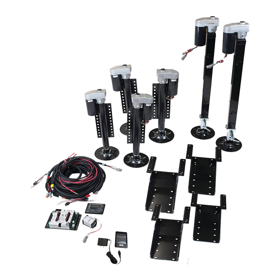
GROUND CONTROL 3.0 COMPONENTS


| Callout | Part # | Description |
| A | 305340 | Hall Effect Landing Gear; Front Stroke 19.8125" |
| B | 305339 | Left Hall Effect Jack; Rear and Middle 12.5" Stroke |
| C | 344792 | Right Hall Effect Jack; Rear and Middle 12.5" Stroke |
| D | 342610 | Hall Effect Jack; Rear Short 10.5" Stroke |
| E | 343758 | Hall Effect Jack Motor |
| F | 119113 | Bolt On Pull Pin |
| G | 134989 | Weld On Jack Mounting Bracket (OEM Only) |
| H | 349975 | Bolt On Jack Mounting Bracket (Aftermarket Only) |


| Callout | Part # | Description |
| I | 178210 | Jack Mounting Nut; ½" - 20 |
| J | 118076 | Jack Mounting Bolt; ½" - 20 x 1 ½" Flange |
| K | 119073 | Top Lock Nut |
| L | 125878 | Carriage Bolt |
| M | 225598 | Snapper Pin; ⅜ x 3" |
| N | 241940 | Rear Sensor Mounting Screw |
| O | 191021 | Hex Head Bolt (Aftermarket Only) |
| P | 231775 | Rear Sensor Mounting Plate |
| Q | 232201 | Rear Sensor |
| R | 333041 | Canbus Terminating Resistor |
| S | 331116 | Canbus Data Harness |


| Callout | Part # | Description |
| T | 425585 | 4 Pin Pigtail Harness |
| U | 329080 | Canbus Power Connector Harness |
| V | 243688 | Rear Sensor Harness |
| W | 267401 | Linc Remote Charger |
| X | 231775 | OneControl Touch Panel |
| Y | 406345 | Auto Leveling Control Touch Panel |
| Z | 329164 | Linc Remote |
| AA | 433943 | 4 Point Controller |
| AB | 433940 | 6 Point Controller |
The contents of this manual are proprietary and copyright protected by Lippert Components, Inc. ("LCI"). LCI prohibits the copying or dissemination of portions of this manual unless prior written consent from an authorized LCI representative has been provided. Any unauthorized use shall void any applicable warranty. The information contained in this manual is subject to change without notice and at the sole discretion of LCI. Revised editions are available for free download from www.lci1.com.
Please recycle all obsolete materials.
For all concerns or questions, please contact Lippert Components, Inc.
Ph: (574) 537-8900 | Web: lci1.com | Email: customerservice@lci1.com

VideosLippert Ground Control 3.0 Review Video
Documents / Resources
References
Download manual
Here you can download full pdf version of manual, it may contain additional safety instructions, warranty information, FCC rules, etc.
Advertisement


Need help?
Do you have a question about the Ground Control 3.0 and is the answer not in the manual?
Questions and answers