Lippert Components ground control 3.0 Owner's Manual
5th wheel 4 point and 6 point
Hide thumbs
Also See for ground control 3.0:
- User manual ,
- Service manual (28 pages) ,
- Owner's manual (24 pages)

Related Manuals for Lippert Components ground control 3.0


Summary of Contents for Lippert Components ground control 3.0
- Page 1 Ground Control 3.0 (5th Wheel) 4 Point and 6 point OWNER'S MANUAL Page 1 Rev: 08.04.2016 Ground Control® 3.0 Owner's Manual...
-
Page 2: Table Of Contents
Failure to act in accordance with the following may result in death or serious personal injury. The use of the Ground Control 3.0 leveling system to support the trailer for any reason other than which it is intended is prohibited by Lippert’s limited warranty. -
Page 3: Prior To Operation
Prior To Operation The leveling system should only be operated under the following conditions: The trailer is parked on a reasonably level surface. Be sure all persons, pets, and property are clear of the trailer while the leveling system is in operation. Make sure battery(ies) are fully charged and test at 12+VDC under load. -
Page 4: Operation
Operation Be sure to park the trailer on solid, level ground. Clear all jack landing locations of debris and obstructions. Locations should also be free of depressions. When parking the trailer on extremely soft surfaces, utilize load distribution pads under each jack. People and pets should be clear of the trailer while operating leveling system. -
Page 5: Auto Level
Fig. 2 Auto Level After unhitching from tow vehicle and parking the tow vehicle at a safe distance away from the trailer, press the “ON/OFF” button (Fig. 1K) and then press “AUTO LEVEL” (Fig. 1F). NOTE: Once the automatic leveling cycle has been started, it is important that there is no movement in the trailer until the trailer has completed the leveling process. -
Page 6: Hitch Recognition
NOTE: If the AUTO LEVEL sequence does not perform as described, place the system in manual mode and test that the jacks operate correctly by pushing their coordinating buttons on the touch pad; i.e. "FRONT" button operates only the front jacks. Hitch Recognition Fig. - Page 7 Fig. 6 Fig. 7 Fig. 8 Bottom of Jack Motor Override: Tools needed: 3/8” drive ratchet and extension, 5/16” socket Find the port on the bottom of the jack motor (Fig. 9A). Remove the rubber plug (Fig. 10A). Insert the 5/16” socket into the port (Fig. 11). Turn override until the jack extends or retracts to desired position.
-
Page 8: Troubleshooting - Touch Pad
Troubleshooting - Touch Pad NOTE: To clear an error code from the touch pad, repair or otherwise correct the issue, then press “ENTER.” If the error is still present, the message will be displayed again. LCD Message What's Happening? What Should Be Done? Controller not properly secured. -
Page 9: Special Jack Error Codes
Special Jack Error Codes To clear one of the error codes listed below: Correct or otherwise repair the issue (see the table below). NOTE: In order to clear the special jack error code the jacks need to be "homed". In order to "home" jacks, each jack MUST be able to retract a minimum of 6 inches. -
Page 10: Preventive Maintenance
Preventive Maintenance For optimum performance, the system requires full battery current and voltage. The battery MUST be maintained at full capacity. Check the terminals and other connections at the battery, the controller, and the jacks for corrosion, and loose or damaged connections. Remove dirt and road debris from jacks as needed. -
Page 11: Ground Control 3.0 Oem Assembly
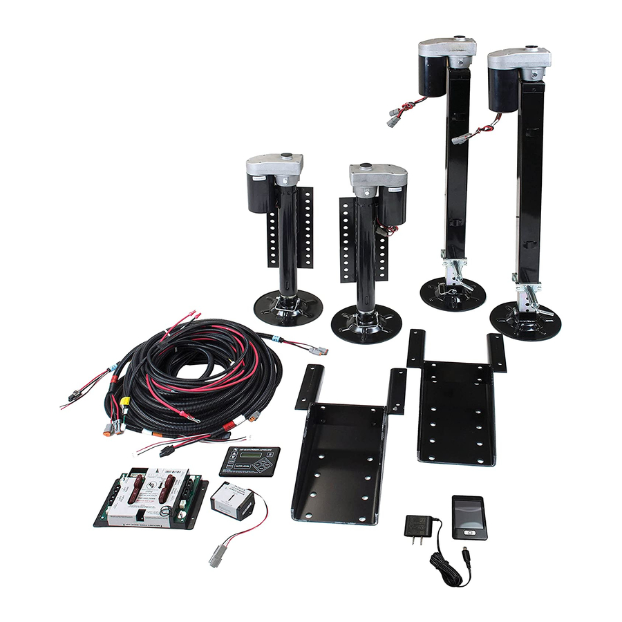
GROUND CONTROL 3.0 OEM ASSEMBLY LEVELING AND STABILIZATION Hall Effect Jack Mounting Bolt Jacks; Rear Left Jack Mounting Nut And Middle Snapper Pin Bolt On Pull Pin Landing Gear Carriage Bolt Hall Effect Jacks; Rear Right And Middle Jack Mounting... -
Page 12: Ground Control 3.0 Components
GROUND CONTROL 3.0 COMPONENTS LEVELING AND STABILIZATION Callout Part # Description 305340 Hall Effect Landing Gear; Front Stroke 19.8125" 305339 Hall Effect Jack; Rear Left 12.5" Stroke 344792 Hall Effect Jack; Rear Right 12.5" Stroke 342610 Hall Effect Jack; Rear Short 10.5" Stroke... - Page 13 GROUND CONTROL 3.0 COMPONENTS LEVELING AND STABILIZATION Callout Part # Description 178210 Jack Mounting Nut; 1/2" - 20 118076 Jack Mounting Bolt; 1/2" - 20 x 1 1/2" Flange 119073 Top Lock Nut 125878 Carriage Bolt 225598 Snapper Pin; 3/8 x 3"...
- Page 14 GROUND CONTROL 3.0 COMPONENTS LEVELING AND STABILIZATION Callout Part # Description 232201 Rear Sensor 232937 LCD Touch Pad Harness 243688 Rear Sensor Harness 267401 Linc Remote Charger 234802 LCD Touch Pad 329164 Linc Remote 304136 4-Point Hall Effect Canbus Wireless Ground Control Controller...
-
Page 15: Ground Control 3.0 Components
GROUND CONTROL 3.0 COMPONENTS LEVELING AND STABILIZATION Callout Part # Description 305115 Hall Effect Right Rear Sensor Harness 306298 Hall Effect Left Rear Sensor Harness 307489 Hall Effect Right Front Sensor Harness 307490 Hall Effect Left Front Sensor Harness 347012... - Page 16 The contents of this manual are proprietary and copyright protected by Lippert Components, Inc. (“LCI”). LCI prohibits the copying or dissemination of portions of this manual unless prior written consent from an authorized LCI representative has been provided. Any unauthorized use shall void any applicable warranty. ...
Need help?
Do you have a question about the ground control 3.0 and is the answer not in the manual?
Questions and answers