Lippert Components Level-Up Owner's Manual
5th wheel
Hide thumbs
Also See for Level-Up:
- Owner's manual (28 pages) ,
- Manual (20 pages) ,
- Installation and owner's manual (20 pages)
Table of Contents
Advertisement
Advertisement
Table of Contents

Related Manuals for Lippert Components Level-Up


Summary of Contents for Lippert Components Level-Up
- Page 1 Level-Up 5th Wheel OWNER'S MANUAL ®...
-
Page 2: Table Of Contents
The Level-Up hydraulic system is equipped with 14K aluminum landing gear and 8K aluminum leveling jacks. The leveling jacks in the Level-Up® system work in pairs. A 12V DC electric motor drives a hydraulic pump that moves fluid through a system of hoses, fittings and jacks to level and stabilize the 5th Wheel. -
Page 3: Product Features
The Level-Up LCD 5th Wheel Leveling System is designed as a leveling system only and should not be used for any reason to provide service under the trailer, e.g. changing tires or servicing the leveling system. -
Page 4: Preparation
Moving parts can pinch, crush or cut. Keep clear and use caution. Make sure all persons, pets and property are clear of the 5th Wheel while LCI Level-Up Automatic Leveling system is in operation. -
Page 5: Operation
Operation Use the LCD touchpad (Fig. 1) to operate the Level-Up hydraulic system. Fig. 1 Gray Black LEDs LEDs LCD Touchpad Features Callout Description Up Arrow - Scrolls up through the menu on LCD. Down Arrow - Scrolls down through the menu on LCD. -
Page 6: Unhitching Instructions
(Figs. 1A and 1B), then press ENTER (Fig. 1C) to select the desired mode Press the LEFT or RIGHT buttons (Fig. 1H or 1I) to operate Level-Up jacks on the left (roadside) or right (curbside) side of the 5th Wheel, respectively. -
Page 7: Zero Point Calibration
Zero Point Calibration The “Zero Point” is the programmed point in which the 5th Wheel will return to whenever the auto- level feature is used. The Zero Point is preset at the factory and should never have to be rest. However, if necessary, Zero Point can be reset. -
Page 8: Manual Override
Manual Override The LCI Level-Up® LCD 5th Wheel Leveling system can be manually operated with an electric drill. In the event of electrical or system failure, this manual override method of extending and retracting the jacks can be used. NOTE: Unhook the hydraulic power unit motor from the main power source (battery or shore power) prior to attempting the manual override procedure. - Page 9 NOTE: Steps 2-5 are identical for both 4-Point and 6-Point Leveling Systems. Using a 5/32” hex wrench, open the valve by turning the manual override set screw clockwise (Fig. 8). Remove protective label (Fig. 9A) from power unit motor to reveal the manual override coupler. Using an electric drill with a 1/4”...
-
Page 10: Troubleshooting
Troubleshooting Error Display In LCD Screen To clear an Error Code, repair, correct the issue or press ENTER button (Fig. 1C). If the error remains, the error message will reappear. Error Codes LCD Message What's Happening? What Should Be Done? Check and secure controller placement. -
Page 11: Maintenance
Fluid Recommendation The LCI Level-Up Automatic Leveling system is pre-filled, primed and ready to operate direct from the manufacturer. Type “A” Automatic Transmission Fluid (ATF) is utilized. Lippert Components, Inc. -
Page 12: 4-Point Wiring Diagram
4-Point Wiring Diagram Controller Touchpad Pressure Switch Rear Sensor Landing Gear Fuse Road Side Valve Dual Polarity Solenoid Curb Side Valve Circuit Protection requirement is 50-100 A as needed by RVIA standards and OEM requirements. Power Unit Battery Page 12 Rev: 02.14.19 CCD - 0001531... -
Page 13: 4-Point Hydraulic Diagram
4-Point Hydraulic Diagram Black Orange Front Retract Front Extend Left Front Landing Gear Right Front Landing Gear Orange Hydraulic Power Unit Black Retract Orange Black Front Extend Extend Orange Rear Retract Front Retract Rear Extend Black Orange Left Rear Right Rear Leveling Jack Leveling Jack Rear Retract... -
Page 14: 6-Point Wiring Diagram
6-Point Wiring Diagram Controller Touchpad Rear Sensor Valve Dual Polarity Fuse Solenoid Road Side Curb Side Pressure Switch Circuit Protection requirement is 50- 100 A as needed by Power Unit RVIA standards and Battery OEM requirements. Page 14 Rev: 02.14.19 CCD - 0001531... -
Page 15: 6-Point Hydraulic Diagram
6-Point Hydraulic Diagram Power Unit Valve Landing Landing Gear Gear Valve Pressure Switch Extend Retract Valve Block Valve Block Leveling Leveling Mid Jack Mid Jack Leveling Leveling Rear Jack Rear Jack Page 15 Rev: 02.14.19 CCD - 0001531... -
Page 16: Level-Up Level-Up
LEVEL-UP TOWABLE 5TH WHEEL 4-POINT ASSEMBLY ® LEVELING & STABILIZATION Power Unit Assembly 14K Landing Gear Controller LCD Control Touchpad 8K Leveling Jacks Rear Leveling Sensor Page 16 Rev: 02.14.19 CCD - 0001531... -
Page 17: Towable 5Th Wheel 6-Point Assembly
LEVEL-UP TOWABLE 5TH WHEEL 6-POINT ASSEMBLY ® LEVELING & STABILIZATION Controller 14K Landing Gear Power Unit Assembly LCD Control Touchpad 8K Mid Leveling Jacks 8K Rear Leveling Jacks Rear Leveling Sensor Page 17 Rev: 02.14.19 CCD - 0001531... -
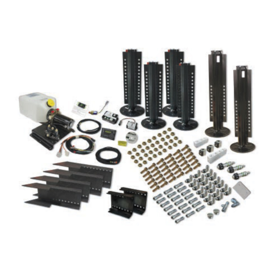
Page 18: Level-Up ® Towable Components
LEVEL-UP TOWABLE COMPONENTS ® LEVELING & STABILIZATION NOTE: Part numbers are shown for identification purposes only. Not all parts are available for individual sale. All parts with a link to the Lippert Store can be purchased. Original Current Callout Part #... - Page 19 LEVEL-UP TOWABLE COMPONENTS ® LEVELING & STABILIZATION Gray Black Callout Part # Description 421484 LCD Touch Pad (Gray) 234802 LCD Touch Pad (Black) 241316 Touch Pad Harness 237855 Deutsch 2 Wire Pigtail Harness 241129 Controller *135461 80 AMP 12V Breaker...
- Page 20 LEVEL-UP TOWABLE COMPONENTS ® LEVELING & STABILIZATION Callout Part # Description 195860 8K Jack, 8 Hole Black 1958604 8K Jack, 8 Hole Silver 433458 8K Jack, 13 Hole Black 43345810 8K Jack, 13 Hole Silver 275125 14K Landing Gear, 6 Hole Black (RH)
-
Page 21: Towable Components
LEVEL-UP TOWABLE COMPONENTS ® LEVELING & STABILIZATION Callout Part # Description 1/2" 1/2" 118076 Bolt, - 20 x 1 1/2" 178210 Nut, - 20 134989 Mount Bracket (Weld-On) 218210 Front Mount Bracket (Weld-On) 324269 Footpad Kit 364372 Footpad 123932 O-Ring Seal (2x) 3/4"... - Page 22 LEVEL-UP TOWABLE COMPONENTS ® LEVELING & STABILIZATION Callout Part # Description 113042 Hose Union Fitting 113131 Straight Fitting 113128 JIC to O-Ring 90-Degree Elbow Fitting 113130 T-Fitting with O-Ring on Run 113134 Swivel Elbow Fitting 113135 Swivel T-Fitting 113129 45-Degree Elbow Fitting...
-
Page 23: Level-Up ® Towable Components
LEVEL-UP TOWABLE COMPONENTS ® LEVELING & STABILIZATION Callout Part # Description 138420 Manifold 138421 Restricted Manifold 166078 Retract Valve Block 248654 Orange Hose 248653 Black Hose 194712 Extend Valve Block 255130 4-Bank Manifold Page 23 Rev: 02.14.19 CCD - 0001531... - Page 24 The contents of this manual are proprietary and copyright protected by Lippert Components, Inc. (“LCI”). LCI prohibits the copying or dissemination of portions of this manual unless prior written consent from an authorized LCI representative has been provided. Any unauthorized use shall void any applicable warranty. ...
Need help?
Do you have a question about the Level-Up and is the answer not in the manual?
Questions and answers