Table of Contents
Advertisement
Quick Links
Advertisement
Table of Contents

Subscribe to Our Youtube Channel
Related Manuals for Aaeon MAX-H310A


Summary of Contents for Aaeon MAX-H310A
- Page 1 MAX-H310A...
- Page 2 E15284 First Edition May 2019 Copyright Notice This document is copyrighted, 2019. All rights are reserved. The original manufacturer reserves the right to make improvements to the products described in this manual at any time without notice. No part of this manual may be reproduced, copied, translated, or transmitted in any form or by any means without the prior written permission of the original manufacturer.
-
Page 3: Table Of Contents
Contents Chapter 1 Product overview Package contents................. 1-1 Features ..................1-1 Specifications ................1-2 Chapter 2 Motherboard information Before you proceed ..............2-1 Motherboard layout ..............2-2 Screw size ..................2-4 2.3.1 Component side .............. 2-4 2.3.2 Solder side ..............2-5 Central Processing Unit (CPU) ........... - Page 4 Contents 3.3.7 PCH-FW Configuration ..........3-12 3.3.8 Power Management ............3-12 3.3.9 Digital IO Port Configuration ......... 3-13 Chipset menu ................3-13 3.4.1 System Agent (SA) Configuration ......... 3-13 3.4.2 PCH-IO Configuration ........... 3-14 Security menu ................3-14 3.5.1 Administrator Password ..........3-14 3.5.2 User Password .............. 3-15 Boot menu ..................
-
Page 5: Chapter 1 Product Overview
Chapter 1 Product overview Package contents Check your industrial motherboard package for the following items. 1 x Industrial Motherboard 1 x SATA Cable 1 x I/O Shield 1 x Support DVD 1 x COM port cable If any of the above items is damaged or missing, contact your distributor or sales representative immediately. -
Page 6: Specifications
Board size 9.6” x 9.6” (244mm x 244mm) Gross weight 1.76 lb (0.8 Kg) Operating 32~140°F (0~60°C) temperature Storage temperature -40°F ~185°F (-40°C ~85°C) Operating humidity 0%~90% relative humidity, non-condensing Power compliance Certificate CE/FCC (continued on the next page) MAX-H310A... - Page 7 DISPLAY Chipset Intel Graphics Media Accelerator ® Output DisplayPort: Up to 4096 x 2160 @ 24 Hz / 3840 x 2160 @ 60 Hz, with Digital Audio HDMI: Up to 4096 x 2160 @ 24 Hz / 2560 x 1600 @ 60 Hz, with Digital Audio VGA: Up to 1920 x 1200 @60Hz (via IT6516B) 3 x SATA III (6.0Gb/s) ports (BOM option: additional 2 SATA)
-
Page 8: Chapter 2 Motherboard Information
Chapter 2 Motherboard information Before you proceed Take note of the following precautions before you install motherboard components or change any motherboard settings. CAUTION! • Unplug the power cord from the wall socket before touching any component. • Before handling components, use a grounded wrist strap or touch a safely grounded object or a metal object, such as the power supply case, to avoid damaging them due to static electricity. • Hold components by the edges to avoid touching the ICs on them. • Whenever you uninstall any component, place it on a grounded antistatic pad or in the bag that came with the component. -
Page 9: Motherboard Layout
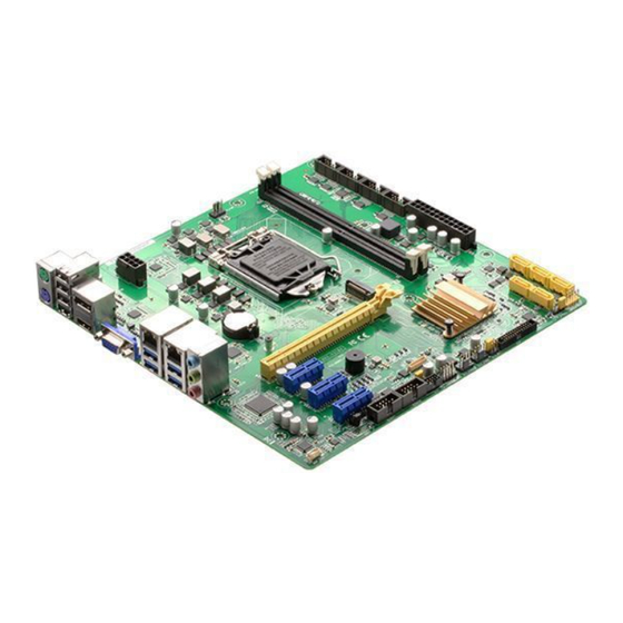
DP_HDMI 1442K LGA1151 Intel LAN1_USB3_12 PHY i219V Place this side towards the rear Intel of the chassis LAN2_USB3_34 I211AT 2280 AUDIO PCIEX16 MAX-H310A Super 128Mb BIOS PCIEX1_1 Intel ® SPI_1 BUZZER1 LED_5VSB H310 LED_5V PCIEX1_2 PCIEX1_3 COM1_J3 COM1_J1 COM1_J2 COM1_J4 COM1_VSET USB2.0... - Page 10 Connectors/Jumpers/Slots Page ATX power connectors (24-pin EATX_PWR1, 8-pin EATX_PWR2) 2-18 Intel LGA1151 CPU socket ® CPU and chassis fan connectors (4-pin CPU_FAN, 4-pin CHA_FAN1~2) 2-19 M.2 M-Key slot 2-21 DDR4 DIMM slots 2-10 Serial port connectors (10-1 pin COM1~6) 2-22 BIOS programmable connector (8-pin SPI_1) 2-18 Serial ATA 6.0Gb/s connectors (7-pin SATA6G_1~3, SATA6G_E4/E5) 2-21 System panel connector (10-1 pin F_PANEL) 2-20 10. Chassis intrusion connector (4-1 pin CHASSIS) 2-14 11. LPC Box header (26-pin LPC) 2-24 12. Clear RTC RAM (CLRTC) 2-12 2-15 13. Intel ® ME Jumper (3-pin DIS_ME) 14. USB 2.0 connector (10-1 pin USB2.0) 2-23 15.
-
Page 11: Screw Size
236.09 228.09 232.07 217.57 216.92 189.59 179.94 173.61 167.83 156.16 156.16 149.10 144.09 143.26 130.76 126.81 120.56 114.88 101.41 101.22 83.24 71.77 67.20 62.63 60.15 62.28 56.40 45.45 45.45 42.75 14.78 11.84 10.49 7.36 7.90 5.85 0.00 7.06 35.17 MAX-H310A... -
Page 12: Solder Side
2.3.2 Solder side 237.49 237.49 195.23 165.10 165.10 164.31 151.99 144.81 126.81 108.81 89.31 65.66 33.02 10.16 0.00 Chapter 2: Motherboard information... -
Page 13: Central Processing Unit (Cpu)
Central Processing Unit (CPU) The motherboard comes with a surface mount LGA1151 socket designed for the Intel 8th Generation(Coffee Lake-S) Core™ i7/ i5 /i3, Pentium 14nm LGA 1151 ® socket Processor. MAX-H310A CPU socket LGA1151 IMPORTANT: Unplug all power cables before installing the CPU. CAUTION! • Upon purchase of the motherboard, ensure that the PnP cap is on the socket and the socket contacts are not bent. Contact your retailer immediately if the PnP cap is missing, or if you see any damage to the PnP cap/socket contacts/motherboard components. The manufacturer will shoulder the cost of repair only if the damage is shipment/transit-related. • Keep the cap after installing the motherboard. The manufacturer will process Return Merchandise Authorization (RMA) requests only if the motherboard comes with the cap on the LGA1151 socket. • The product warranty does not cover damage to the socket contacts resulting from incorrect CPU installation/removal, or misplacement/loss/ incorrect removal of the PnP cap. MAX-H310A... -
Page 14: Installing The Cpu
2.4.1 Installing the CPU CAUTION! Ensure that you install the correct CPU designed for LGA 1151 only. DO NOT install a CPU designed for LGA1155 and LGA1156 sockets on the LGA1151 socket. Chapter 2: Motherboard information... -
Page 15: Cpu Heatsink And Fan Assembly Installation
2.4.2 CPU heatsink and fan assembly installation CAUTION! Apply the Thermal Interface Material to the CPU heatsink and CPU before you install the heatsink and fan if necessary. To install the CPU heatsink and fan assembly MAX-H310A... - Page 16 To uninstall the CPU heatsink and fan assembly Chapter 2: Motherboard information...
-
Page 17: System Memory
System memory This motherboard comes with two Double Data Rate 4 (DDR4) Dual Inline Memory Module (DIMM) sockets. A DDR4 module is notched differently from a DDR, DDR2, or DDR3 module. DO NOT install a DDR, DDR2, or DDR3 memory module to the DDR4 slot. According to Intel CPU spec, DIMM voltage below 1.2 V is recommended to protect the ® CPU. MAX-H310A 288-pin DDR4 DIMM sockets 2.5.1 Installing a DIMM MAX-H310A 2-10... - Page 18 To remove a DIMM Chapter 2: Motherboard information 2-11...
-
Page 19: Jumpers
Clear RTC RAM (CLRTC) This jumper allows you to clear the Real Time Clock (RTC) RAM in CMOS. You can clear the CMOS memory of date, time, and system setup parameters by erasing the CMOS RTC RAM data. The onboard button cell battery powers the RAM data in CMOS, which include system setup information such as system passwords. CLRTC Normal Clear RTC (Default) MAX-H310A Clear RTC RAM To erase the RTC RAM: 1. Turn OFF the computer and unplug the power cord. 2. Move the jumper cap from pins 1-2 (default) to pins 2-3. Keep the cap on pins 2-3 for about 5~10 seconds, then move the cap back to pins 1-2. 3. Plug the power cord and turn ON the computer. 4. Hold down the <Del> key during the boot process and enter BIOS setup to reenter data. CAUTION! Except when clearing the RTC RAM, never remove the cap on CLRTC jumper default position. Removing the cap will cause system boot... - Page 20 MAX-H310A COM1 RS422/RS485 Terminator (J1/J2/J3/J4) AT/ATX Mode selection (3-pin ATX_AT) ATX_AT ATX mode AT mode (Default) MAX-H310A H/W AT/ATX mode selection Pins 1-2 (Default) ATX mode AT mode NOTE: Jumper setting of ATX_AT should be consistent with the setting of Power Mode in BIOS. Refer to section 3.3.8 Power Management in Chapter 3. Chapter 2: Motherboard information...
- Page 21 This connector is for a chassis-mounted intrusion detection sensor or switch. Connect one end of the chassis intrusion sensor or switch cable to this connector. The chassis intrusion sensor or switch sends a high-level signal to this connector when a chassis component is removed or replaced. The signal is then generated as a chassis intrusion event. By default, the pin labeled “Chassis Signal” and “Ground” are shorted with a jumper cap. Remove the jumper caps only when you intend to use the chassis intrusion detection feature. CHASSIS MAX-H310A Chassis intrusion connector COM1 Ring/+5V/+12V selector (6-pin COM1_VSET) COM1_VSET +12V Ring (Default) MAX-H310A COM1 Ring/+5V/+12V Selection Setting Pins...
- Page 22 Intel ME Jumper (3-pin DIS_ME) ® This jumper allows you to force the Intel Management Engine (ME) to boot ® from recovery mode when ME becomes corrupted. DIS_ME Enabled ME flash security (Default) Enabled ME flash security Disabled ME flash security MAX-H310A Intel ME flash security selection ® Chapter 2: Motherboard information 2-15...
-
Page 23: Connectors
BLINKING Data activity GREEN 1 Gbps connection LAN port Line In port (light blue). This port connects to the tape, CD, DVD player, or other audio sources. Line Out port (lime). This port connects to a headphone or a speaker. Microphone port (pink). This port connects to a microphone. MAX-H310A 2-16... - Page 24 USB 3.1 Gen 1 ports (Blue, Type-A). These 9-pin Universal Serial Bus (USB) ports are for USB 3.1 Gen 1 devices. NOTES: • We strongly recommend that you connect USB 3.1 Gen 1 devices to USB 3.1 Gen 1 ports for faster and better performance from your USB 3.1 Gen 1 devices. • Due to the design of the Intel 300 series chipset, all USB devices ® connected to the USB 2.0 and USB 3.1 Gen 1 ports are controlled by the xHCI controller. Some legacy USB devices must update their firmware for better compatibility. Video Graphics Adapter (VGA) port. This 15-pin port is for a VGA monitor or other VGA-compatible devices. NOTE: Disable LVDS support when using only the VGA port. Refer to the section on System Agent (SA) Configuration in Chapter 3 for details. 10. HDMI port. This port is for a High-Definition Multimedia Interface (HDMI) connector, and is HDCP compliant allowing playback of HD DVD, Blu-ray, and other protected content. 11. PS/2 Keyboard port (purple). This port is for a PS/2 keyboard. Chapter 2: Motherboard information 2-17...
-
Page 25: Internal Connectors
+12V DC Power OK -5 Volts +5 Volts +5 Volts PSON# +3 Volts -12 Volts +3 Volts +3 Volts PIN 1 MAX-H310A ATX power connectors IMPORTANT: • For a fully configured system, we recommend that you use a power supply unit (PSU) that complies with ATX 12 V Specification 2.0 (or later version) and provides a minimum power of 330W. • We recommend that you use a PSU with higher power output when configuring a system with more power-consuming devices. The system may become unstable or may not boot up if the power is inadequate. BIOS programmable connector (8-pin SPI_1) Use this connector to flash the BIOS ROM. - Page 26 Front panel audio connector (10-1 pin AAFP) This connector is for a chassis-mounted front panel audio I/O module that supports HD Audio standard. Connect one end of the front panel audio I/O module cable to this connector. AAFP MAX-H310A Front panel audio connector IMPORTANT: We recommend that you connect a high-definition front panel audio module to this connector to avail of the motherboard’s high-definition audio capability. CPU and chassis fan connectors (4-pin CPU_FAN, 4-pin CHA_FAN1~2) Connect the fan cables to the fan connectors on the motherboard, ensuring that the black wire of each cable matches the ground pin of the connector.
- Page 27 System panel connector (10-1 pin F_PANEL) This connector supports several chassis-mounted functions. F_PANEL PWR_LED PWR_BTN PIN 1 HDD_LED RESET MAX-H310A Front panel connector • System power LED (2-pin PWR_LED) This 2-pin connector is for the system power LED. Connect the chassis power LED cable to this connector. The system power LED lights up when you turn on the system power, and turns off when the system is in ACPI-S3/ S4/S5 mode by default. • Hard disk drive activity LED (2-pin HDD_LED) This 2-pin connector is for the HDD Activity LED. Connect the HDD Activity LED cable to this connector. The HDD LED lights up or flashes when data is read from or written to the HDD. • ATX power button/soft-off button (2-pin PWR_BTN) This 2-pin connector is for the system power button.
- Page 28 RSATA_RXN5 RSATA_TXN4 RSATA_RXP5 RSATA_TXP4 MAX-H310A Intel SATA 6 Gb/s connectors ® NOTE: When using hot-plug and NCQ, set the SATA Mode Selection item in the BIOS to [AHCI]. See section 3.3.3 SATA Configuration for details. M.2 M-key 2280 socket This socket allows you to install an M.2 (NGFF) SSD module. M2_TYPE_M 2280 MAX-H310A M.2 (M-key) Chapter 2: Motherboard information 2-21...
- Page 29 PIN 1 COM5 COM1 COM2 PIN 1 PIN 1 PIN 1 COM4 PIN 1 COM3 PIN 1 MAX-H310A Serial port (COM) connectors NOTE: • The COM module is purchased separately. • COM1 also supports RS-232 / RS-422 / RS-485. See the table below and section 3.3.2 Super IO Configuration for details. Signal Pin Signal DCD# (422TXD-/485DATA-) RXD (422TXD+/485DATA+) TXD (422RXD+)
- Page 30 Audio amplfier connector (4-pin AMP_CON) This connector is for an internal stereo amplifier speakers support (2W/4 via WtoB header). AMP_CON PIN 1 MAX-H310A Audio Stereo Output with Amp connector 10. USB 2.0 connector (10-pin USB2.0) This USB connectors complies with USB 2.0 specifications. USB2.0 PIN 1 MAX-H310A USB2.0 connector Never connect a 1394 cable to the USB connector. Doing so will damage the motherboard. Chapter 2: Motherboard information 2-23...
- Page 31 11. LPC Box header (26-pin LPC) PIN 1 MAX-H310A LPC Connector for IPC BU 12. Digital I/O connector (10-pin DIO) This connector includes 8 I/O lines (In/Out programmable). All of the Digital I/O lines are programmable and each I/O pin can be individually programmed to support various devices. DIO1 PIN 1 MAX-H310A Digitial I/O connector MAX-H310A 2-24...
-
Page 32: Chapter 3 Bios Setup
Chapter 3 BIOS setup BIOS setup program Use the BIOS Setup program to configure its parameters. The BIOS screens include navigation keys and brief online help to guide you in using the BIOS Setup program. Entering BIOS Setup at startup To enter BIOS Setup at startup: Press <Delete>... -
Page 33: Bios Menu Screen
The Main menu provides you an overview of the basic system information, and allows you to set the system date, time, language, and security settings. 3.2.1 System Date [Day MM/DD/YYYY] Allows you to set the system date. 3.2.2 System Time [HH:MM:SS] Allows you to set the system time. MAX-H310A... -
Page 34: Advanced Menu
Advanced menu The Advanced menu items allow you to change the settings for the CPU and other system devices. Be cautious when changing the settings of the Advanced menu items. Incorrect field values can cause the system to malfunction. Case Open Warning [Disabled] Allows you to enable or disable the case open detecting function. - Page 35 Selects to tell operating system to support PPI Spec Version 1.2 or 1.3. Some HCK tests might not support 1.3. Configuration options: [1.2] [1.3] PH Randomization [Disabled] Allows you to select the PH Randomization. Configuration options: [Disabled] [Enabled] Device Select [Auto] Allows you to select the TPM device. Configuration options: [Auto] [TPM1.2] [TPM2.0] MAX-H310A...
-
Page 36: Sata Configuration
3.3.3 SATA Configuration The BIOS automatically detects the presence of SATA devices. The Serial ATA Ports listed will display Empty if there are no Serial devices connected to the ports. SATA Controller(s) [Enabled] Configuration options: [Enabled] [Disabled]. The following items appear only when you set SATA Controller(s) to [Enabled]. SATA Mode Selection [AHCI] Allows you to set the SATA configuration. -
Page 37: Hardware Monitor
The following items appear only when you set Fan Control Mode to [Thermal Cruise Mode]. Target Temperature [50] Input value range: [0~127] Tolerance of Temperature [0] Input value range: [0~7] Fan Out Start-Up Value [127] Input value range: [0~255] MAX-H310A... - Page 38 Fan Stop Duty [Down to 0] Selects fan stop duty mode. Configuration options: [Down to 0] [To Fan Out Stop Value] Fan Out Stop Value [100] The Fan Out value decreases to this value if the temperature reaches below the lowest temperature limit. Input value range: [0~255] Fan Out Stop Time [60] Determines the amount of time it takes for the Fan Out value to fall from the stop value to zero.
- Page 39 Fan Control. Input value range: [0~255] The following items appear only when you set Fan Control Mode to [Thermal Cruise Mode]. Target Temperature [50] Input value range: [0~127] Tolerance of Temperature [0] Input value range: [0~7] MAX-H310A...
- Page 40 Fan Out Start-Up Value [127] Input value range: [0~255] Fan Stop Duty [To Fan Out Stop Value] Selects fan stop duty mode. Configuration options: [Down to 0] [To Fan Out Stop Value] Fan Out Stop Value [100] The Fan Out value decreases to this value if the temperature reaches below the lowest temperature limit.
-
Page 41: Sio Configuration
Possible [Use Automatic Settings] Allows you to select an optimal setting for Super I/O devices. Configuration options: [Use Automatic Settings] [IO=3F8h; IRQ=4;] [IO=3E8h; IRQ=7] Mode [RS-232] Allows you to select the Serial Port mode. Configuration options: [RS-232] [RS-422] [RS-485] MAX-H310A 3-10... - Page 42 [*Active*] Serial Port 2 Use this device [Enabled] Allows you to enable or disable this logical device. Configuration options: [Enabled] [Disabled] Possible [Use Automatic Settings] This item appears only when you set Use this device to [Enabled] and allows you to select an optimal setting for Super I/O devices. Configuration options: [Use Automatic Settings] [IO=3E8h;...
-
Page 43: Pch-Fw Configuration
The system goes into on state after an AC power loss. [Always Off] The system goes into off state after an AC power loss. RI Wake Event [Disabled] Enable or disable system wake up from RI#. Configuration options: [Enabled] [Disabled] MAX-H310A 3-12... -
Page 44: Digital Io Port Configuration
RTC Wake system from S5 [Disabled] [Disabled] Disables system wake up from S5. [Fixed Time] The system will wake up at the specified hr::min::sec. Configuration options: [Disabled] [Enabled] . [Dynamic Time] The system will wake up at the current time plus a specified number of minutes. -
Page 45: Pch-Io Configuration
Administrator Password If you have set an administrator password, we recommend that you enter the administrator password for accessing the system. Otherwise, you might be able to see or change only selected fields in the BIOS setup program. MAX-H310A 3-14... -
Page 46: User Password
To set an administrator password: Select the Administrator Password item and press <Enter>. From the Create New Password box, key in a password, then press <Enter>. Confirm the password when prompted. To change an administrator password: Select the Administrator Password item and press <Enter>. From the Enter Current Password box, key in the current password, then press <Enter>. -
Page 47: Boot Menu
This option allows you to exit the Setup program without saving your changes. When you select this option or if you press <Esc>, a confirmation window appears. Select Yes to discard changes and exit. Restore Defaults Restores / Load Default values for all the setup options. MAX-H310A 3-16... -
Page 48: Appendix
Check local regulations for disposal of electronic products. DO NOT throw the mercury-containing button cell battery in municipal waste. This symbol of the crossed out wheeled bin indicates that the battery should not be placed in municipal waste. MAX-H310A... - Page 49 印 刷 電 路 板 及 其 × ○ ○ ○ ○ ○ 電子組件 外 部 信 號 連 接 頭 × ○ ○ ○ ○ ○ 及線材 ○: 表示該有毒有害物質在該部件所有均質材料中的含量均在 SJ/T 11363- 2006 標准規定的限量要求以下。 ×: 表示該有毒有害物質至少在該部件的某一均質材料中的含量超出 SJ/T 11363-2006 標准規定的限量要求,然該部件仍符合歐盟指令 2002/95/ EC 的規范。 備註:此產品所標示之環保使用期限,係指在一般正常使用狀況下。 MAX-H310A...
Need help?
Do you have a question about the MAX-H310A and is the answer not in the manual?
Questions and answers