
Related Manuals for AccuLine CNQplus 1000RT

Summary of Contents for AccuLine CNQplus 1000RT
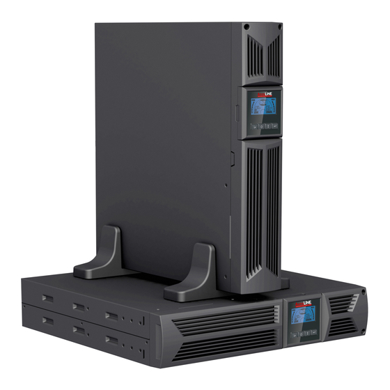
- Page 1 USER MANUAL Acculine CNQplus- Rack/Tower 1000/2000/3000VA ONLINE UPS Edition, February 2018 UNINTERRUPTIBLE POWER SUPPLY...
-
Page 2: Table Of Contents
CONTENTS 1. Safety and EMC Instructions ..............3 1.1 Installation ....................3 1.2 Operation ....................9 1.3 Maintenance, servicing and faults ............10 1.4 Transport ....................13 1.5 Storage ....................13 1.6 Standards ....................14 2. Description of Commonly Used Symbols .......... 15 3. - Page 3 9.3 Battery Replacement ................34 10. Technical Data ..................35 10.1 Electrical specifications ............... 35 10.2 Operating Environment ............... 35 10.3 Typical backup time (Typical values at 25°C in minutes:)....... 35 10.4 Dimensions and weights ............... 36 11. Communication ................... 37 11.1 RS-232 and USB communication ports ..........
-
Page 4: Safety And Emc Instructions
1. Safety and EMC Instructions Please read carefully the following user manual and the safety instructions before installing the unit or using it! 1.1 Installation Read installation instructions before connecting to the mains. Condensation may occur if the UPS is moved directly from a cold to a warm environment. - Page 5 1.1.2 Unpacking the Cabinet To unpack the system: 1. Open the outer carton and remove the accessories packaged with the cabinet. 2. Carefully lift the cabinet out of the outer carton and set it on a flat, stable surface. 3. Discard or recycle the packaging in a responsible manner, or store it for future use.
- Page 6 4. Tighten the screws, and then the load can be connected. 1.1.4 EBM Installation (Optional) UPS Acculine CNQplus series include external battery port that allows users to connect multiple EBMs in order to provide additional backup time. Follow the below procedure to install one or multiple EBM.
- Page 7 2. Tighten the screws on the metal sheet for stabilization 3. Connect the Earth line from the UPS (port A ) to EBM (port B) 4. Take off the front panel, and connect the battery terminal (A) from UPS to EBM terminal (B) shown as below.
- Page 8 Connecting one EBM in a rack form 1. Using the same method as assembling the UPS in a rack form, assemble EBM into the rack-mounting on the top or bottom of the UPS. 2. Connect the earth line from UPS (port A ) to EBM (port B ) 3.
- Page 9 Connecting multiple EBMs in Tower form 1. Connect Earth line between the UPS and the first EBM, then connect the Earth Line between the first EBM and the second EBM. 2. Take off the front panel, and connect the battery terminal (A) from the UPS to EBM terminal (B) shown as below.
-
Page 10: Operation
Note: Three or more EBMs can be connected to the UPS in the same way as shown above. Note: After connecting the EBMs, please do not forget to set the number of EBMs via the LCD menu for setting procedure. If you are using non-standard EBMs, please call local dealer or distributor for setting method. -
Page 11: Maintenance, Servicing And Faults
For battery wire for all models, use 90 C copper wire 3 x 6 mm² and Anderson PP45 connectors for user external battery cabinet. 1.3 Maintenance, servicing and faults The UPS operates with hazardous voltages. Repairs may be carried out only by qualified maintenance personnel. - Page 12 1.3.3 Time to Replace Batteries When the discharging time after full charging is less than 50% of the specified back-up time, the batteries may need to be replaced. Please contact your local dealer to order new battery. WARNING: Turn off the UPS and disconnect the utility power cord from the wall outlet. Servicing should performed...
- Page 13 4. Remove the inner battery bracket on the right side. 5. Pull the battery pack out onto a flat area. 6. Install the new battery pack into the UPS. 7. Screw the battery bracket back on its place and reconnect the battery cable A and B 8.
-
Page 14: Transport
To test the batteries: 1. Connect the UPS to utility power for at least 48 hours to charge the batteries. 2. Press and hold the I button 1 second to start the battery test on line mode or HE mode. The status display string shows TEST 1.3.6 Recycling the Used Battery: Warning: Never dispose of batteries in fire. -
Page 15: Standards
1.6 Standards * Safety IEC/EN 62040-1 * EMI Conducted Emission......:IEC/EN 62040-2 Category C1 Radiated Emission......:IEC/EN 62040-2 Category C1 Harmonic Current.......:IEC/EN 61000-3-2 Voltage Fluctuation and Flicker..:IEC/EN 61000-3-3 *EMS ESD...........:IEC/EN 61000-4-2 Level 3 RS.............:IEC/EN 61000-4-3 Level 3 EFT............:IEC/EN 61000-4-4 Level 4 SURGE..........:IEC/EN 61000-4-5 Level 4 ...:IEC/EN 61000-4-6 Level 3... -
Page 16: Description Of Commonly Used Symbols
2. Description of Commonly Used Symbols Some or all of the following symbols may be used in this manual. It is suggested that you familiarize yourself with them and understand their meaning:... -
Page 17: Introduction
3. Introduction CNQplus RT serries consist of uninterruptible power supply systems incorporating double-converter technology. They provide perfect protection especially for Novell, Windows NT and UNIX servers. The double-converter principle eliminates all mains power disturbances. A rectifier converts the alternating current from the socket outlet to direct current. -
Page 18: Panel Description
4. Panel Description LCD Screen ON Button/ OFF-Button Select-Button Enter-Button Alarm Silence The Display Panel Switch Function Turns on UPS system: By pressing the ON- ON-Button system is turned on. Deactivates acoustic alarm: By pressing this Button an acoustic alarm can be deactivated in battery mode. Byinstantly touching this Button all acoustic alarms can be deactivated in all modes. - Page 19 The LCD Display Display Function Display Function Input Information Output Information Indicates the input Indicates the output voltage/frequency value, voltage/frequency value, which are displayed which are displayed alternatively. alternatively. Indicates that the input is connected to the mains, Indicates the Output plug. and the input power is supplied from the mains.
-
Page 20: Connection And Operation
5. Connection and Operation Electrical installations and wirings should be done only by qualified electricians in accordance with applicable safety regulations! When installing electrical wirings, pay attention to the nominal amperage of your incoming feeder. 5.1 Inspection Inspect the packaging carton and its contents for damage. Please inform the transport agency or dealer immediately should you find signs of damage. -
Page 21: Battery Charging
(3) EPO Connection: User can select the polarity of EPO, EPO is Normally close as default setting. Normally Open Normally the EPO connector is open on the rear panel. Once the connector is closed with a wire, the UPS will cut off the output until the EPO status is disabled. Disable the EPO status Enable the EPO status Normally Closed... -
Page 22: Test Function
more than 1 second for the UPS to turn on, then the UPS will get into will to turn on UPS, the LCD screen will indicate the status of the UPS. Note: The default setting for bypass mode is no output after the UPS is connected to the utility power and the breaker is turned on. -
Page 23: Operation Procedure Of External Battery Connection
If the alarm in bypass button continuously for more than 1 second to silence it. This action does not affect the warning and fault alarms. If all alarms are too annoying, you can instantly touch , then all alarms will be disabled. If alarms need to be resumed, instantly touch button again. - Page 24 is ground protection) (6) Make sure the wires are fastened and install the UPS front panel back to its place. (7) Connect the loads to the UPS. Then, connect the UPS to the utility power supply and the batteries will be charged. Caution: A DC breaker should be connected between the UPS and the external batteries.
-
Page 25: Operating Modes For All Models
6. Operating Modes for All Models A different string will be displayed on the LCD screen corresponding to the UPS operating mode, all possible strings displayed are shown in the following table. At any time, only one normal operating string or fault string is presented. But the warning, even several warnings will appear in a certain normal operating mode at one time. -
Page 26: Battery Mode
the UPS output to less than 90% of its nominal power capacity. Note: Please follow the following steps to connect a generator Activate the generator and wait until the operation is stable before supplying power of the generator to the UPS (be sure that the UPS is in idle mode). Then turn on the UPS according to the start-up procedure. -
Page 27: No Output Mode
Bypass mode The UPS does not have backup function when in bypass mode. The power used by the load is supplied from the utility power via internal filter. 6.4 NO output mode The LCD display in No output mode is shown in the following diagram. Information about the utility power, the battery level, the UPS output and the load level will be displayed. -
Page 28: Converter Mode
normal range, the power used by the loads is supplied from the utility power via internal filter, so that high efficiency can be achieved. Once the mains is lost or abnormal, the UPS will transfer to battery mode and the load will be continuously supplied by the batteries. -
Page 29: Setting By Lcd Module
7. Setting by LCD Module The output voltage, frequency, Bypass status and operating mode in No output mode or Bypass mode, Eco mode, Two Load segments in output mode, the number of EBM in all modes can be all set directly through the LCD module. - Page 30 will be presented circularly. Only one voltage value can be selected among 208V , 220V , 230V , 240V at one time. Only one frequency value can be selected between 50Hz & 60Hz at one time. Bypass status can be selected as 000 or 001 (wher 000 means Bypass Disable 001 means Bypass...
- Page 31 Here is a example for changing the Operating mode from normal mode to converter mode through the LCD panel. Step 1: OPV after pressing the Enter button; Step 2: OPF after pressing the Select button. Step 3: bYPA after pressing the Select button; Step 4: MOdE after pressing the Select button, press the Enter button to set mode, then UPS will be flickering;...
-
Page 32: Trouble Shooting
8. Trouble Shooting If the UPS system does not operate correctly, check the operating status on the LCD display. Warning String Fault String Site fail SITE Inverter short SHOR Fan fail FANF Overload fault OVLD Battery over voltage HIGH Inverter soft start fail ISFT (over charged) Battery low... - Page 33 Emergency supply Batteries not fully Charge the batteries for at period shorter charged / batteries least than nominal defect 5 - 8 hours and then check value capacity. If the problem still exists, consult your dealer. Fan fail Fan abnormal Check if the fan is operating if not, contact your dealer Battery over...
- Page 34 UPS internal fault Notify dealer fault(Low/high/ Unbalance/soft start) Inverter UPS internal fault Notify dealer fault(Low/high/soft start) Over temperature Over temperature Check the ventilation of the fault UPS, check the ambient temperature and ventilation. NTC open UPS internal fault Notify dealer Inverter short Output short circuit Remove all the loads.
-
Page 35: Maintenance
9. Maintenance 9.1 Operation UPS Acculine CNQplus series contain no user-serviceable parts. If the battery service life (3~5 years at 25°C ambient temperature) has been exceeded, the batteries must be replaced. In this case please contact your dealer. 9.2 Storage If the batteries are stored in temperate climatic zones, they should be charged every three months for 1~2 hours. -
Page 36: Technical Data
10. Technical Data 10.1 Electrical specifications INPUT Model No. 1000RT(S) 2000RT(S) 3000RT(S) Phase Frequency (45~55)/(54~66) Hz Max Current(A) 13.5 OUTPUT Model No. 1000RT(S) 2000RT(S) 3000RT(S) Power rating 1kVA/0.9kW 2kVA/1.8kW 3kVA/2.7kW Voltage 208/220/230/240 ±1% VAC Frequency 50/60 ±0.2 Hz (Battery mode) Wave form sinusoidal BATTERIES... -
Page 37: Dimensions And Weights
10.4 Dimensions and weights Model 1000RT 1000SRT 2000RT 2000SRT 3000RT 3000SRT Net weight (kg) 16.2 19.7 28.6 13.2 Dimension (mm) Case (W x H x D) 438X86.5x436 438X86.5x608 Dimension (mm) (W x H x D) Net weight (kg) 22.2 27.5 40.5 Case Type... -
Page 38: Communication
11. Communication 11.1 RS-232 and USB communication ports To establish communication between the UPS and a computer, connect the computer to one of the UPS communication ports by using an applicable communication cable (not included). NOTE: Only one of the communication ports can be active at one time. The USB port has priority over the RS-232 port. -
Page 39: Usb Port
11.3 USB port The UPS can communicate with a USB-compliant computer by using HID-compatible power management software. To establish communication between the UPS and the computer, connect one end of a USB cable (not included) to the USB port on the UPS, then connect the other end of the USB cable to the USB port on the computer. - Page 40 The following figures show schematic of the dry out/in contacts. Dry out contact schematic Dry in contact schematic The following table shows the options for the dry out/in contacts Dry out signal Description General Alarm Activated when any warning happens On Battery Activated when the UPS operates on battery Battery Low...
-
Page 41: Software
12. Software Free Software Download WinPower WinPower is a brand new UPS monitoring software, which provides user-friendly interface to monitor and control your UPS. This unique software provides complete power protection for multi-computer systems while power failure. With this software, users can monitor and control any UPS on the same LAN no matter how far from the UPSs. -
Page 42: Appendix: Rear Panel
The UPS rear panel description table and pictures are shown below: Description (1000VA&2000VA&3000VA) AC Output EPO / Dry in Communication Port USB Port AC Input Dry out SNMP slot RS232 Earth Line Port CNQplus 1000RT / CNQplus 1000SRT / CNQplus 2000RT CNQplus 2000SRT... - Page 43 CNQplus 3000RT CNQplus 3000SRT The EBM rear panel description table and picture are shown below: Description (CNQplus EBM 1KRT / 2KRT / 3KRT) Earth Line Port CNQplus EBM 1KRT / 2KRT / 3KRT rear panel...
- Page 44 USER MANUAL ACCULINE CNQplus- Rack/Tower 1000/2000/3000VA ONLINE UPS 2018...
- Page 45 ................. 3 ..................3 ..................... 10 ........11 ..................... 15 ..................15 ....................16 .... 17 ....................18 ..............19 ................ 22 ....................22 ....................22 ................ 23 UPS ................24 ................24 UPS ..............25 ..........25 ......25 ........
- Page 46 .............. 39 ..............40 ............40 10.2 ..............40 ....... 40 10.4 ................41 ..................42 USB ..........42 RS-232 ................ 42 USB ................... 43 - Network Management Card ................. 43 ..................44 ..................... 46 ................47 ....................49...
- Page 47 UPS! laser). UPS. 3.5mA.
- Page 48 UPS. 1.1.3 Acculine (Tower)
- Page 49 UPS Acculine CNQplus Rack (EBM Rack Rack: Rack (rack rails Rack Rack Rack...
- Page 50 1.1.4 UPS Acculine CNQplus EBM: UPS & EBM UPS ( EBM (B...
- Page 52 Rack Rack, UPS. UPS ( UPS. EBM (B UPS. Unscrew Unscrew...
- Page 53 EBM (B UPS.
- Page 54 EBM (B UPS. & EBM.
- Page 55 4 mm 0,5 N-m (4.4 lb-in CNQplus-3000SRT. 3 x 6 mm Anderson PP45 Acculine CNQplus.
-
Page 56: Ups
C (77°F) 1.3.3... - Page 57 UPS. UPS. UPS. UPS (A UPS.
- Page 58 1.3.5 ECO model) TEST...
- Page 59 To UPS...
- Page 60 * Safety IEC/EN 62040-1 * EMI Conducted Emission......:IEC/EN 62040-2 Category C1 Radiated Emission......:IEC/EN 62040-2 Category C1 Harmonic Current.......:IEC/EN 61000-3-2 Voltage Fluctuation and Flicker..:IEC/EN 61000-3-3 *EMS ESD...........:IEC/EN 61000-4-2 Level 3 RS.............:IEC/EN 61000-4-3 Level 3 EFT............:IEC/EN 61000-4-4 Level 4 SURGE..........:IEC/EN 61000-4-5 Level 4 ...:IEC/EN 61000-4-6 Level 3 ..: IEC/EN 61000-4-8...
- Page 62 UPS Acculine CNQplus Servers Novell, Windows NT & UNIX. rectifier CNQplus CNQplus 1000 1000S 2000 2000S 3000 3000S...
- Page 63 UPS: By pass inverter Bypass...
- Page 64 Bypass. bypass Bypass Bypass,...
- Page 65 UPS.
- Page 66 3 x 4 mm Acculine CNQplus CNQplus 1000RT(S)/ 2000RT(S) 8 * IEC320 C13 3000RT(S) 8 * IEC320 C13 + 1 * C19...
- Page 67 laser). Normally close (normally open) (normally close)
- Page 68 inverter Bypass menu firmware. floating mode, resting mode,...
- Page 69 UPS, bypass bypass UPS, bypass...
- Page 70 CNQplus-1000RT/1000SRT (3 CNQplus-2000RT/2000SRT ( CNQplus-3000RT/3000SRT OFF. UPS. Anderson PP x 6 mm UPS. GND ( -"...
- Page 71 UPS. UPS. bypass...
-
Page 72: Line Mode)
No output mode) STbY Bypass (Bypass mode) bYPA Line mode) LINE Battery mode) bATT (Battery test mode) TEST ECO (ECO mode) CVCF (Converter mode) Line mode) Line LINE... -
Page 73: Battery Mode)
UPS ( idle mode). Battery mode) (Battery bATT Bypass Bypass Bypass... - Page 74 bYPA Bypass. Bypass Bypass STbY 6.5 EPO ( RPO ( EPO . OFF , EPO.
-
Page 75: Eco
ECO ( high efficiency mode ECO . UPS. UPS. (Winpower). 10msec. CVCF . free run) 50Hz 60Hz). (Winpower). - Page 76 SHOR UPS.
- Page 77 Bypass, ECO LCD. 208V, 220V, 230V 240V. 50Hz 60Hz. Bypass enable / disable . 230Vac Select...
- Page 78 OPF , Bypass bYPA , MOdE , EBM EbM, and LS2 208V , 220V , 230V 240V 50Hz 60Hz Bypass 001 ( «Bypass «Bypass Bypass «Bypass «Bypass UPS , CVF ( « inverter», ECO « », EBM) 1 (load segment 1) 001 ( LCD.
- Page 79 LCD. OPF . MOdE bYPA...
- Page 80 LCD. SITE invert SHOR FANF OVLD HIGH ISFT Inverter (soft start) bLOW bSFT CHGF OVTP inverter TEPH Inverter INVL AMbH Inverter INVH bOPN bUSH OVLD bUSL bUSE bATF bUSS NTCO UPS. Inverter STbY bATT LCD, 4 sec. 5 - 8...
- Page 81 Inverter UPS. UPS. off.
- Page 82 Inverter...
- Page 83 UPS Acculine CNQplus OFF. 5.8. UPS.
- Page 84 10.1 1000RT(S) 2000RT(S) 3000RT(S) (45~55)/(54~66) Hz 13.5 1000RT (S) 2000RT(S) 3000RT(S) 1kVA/0.9kW 2kVA/1.8kW 3kVA/2.7kW 208/220/230/240 ±1% VAC 50/60 ±0.2 Hz ( 1000RT (S) 2000RT(S) 3000RT(S) 3 12V 7Ah 4 12V 9Ah 6 12V 9Ah 10.2 0 C to 40 C <...
- Page 85 10.4 CNQplus 1000RT 1000SRT 2000RT 2000SRT 3000RT 3000SRT (kg) 16.2 19.7 28.6 13.2 (mm) Case 438X86.5x436 438X86.5x608 (mm) 22.2 27.5 40.5 Case...
- Page 86 11.1 RS-232 RS-232. 11.2 RS-232 RS-232 RS232 RS232 (pins) RS-232 pins) RS-232 to UPS...
- Page 87 UPS) 11.3 HID. 11.4 Network Management Card ( UPS Acculine CNQplus Network Management Card. (probe) UPS. Network Management Card, UPS. Network Management Card Network Management Card...
- Page 88 11.5 UPS Acculine CNQplus UPS. Vac/1A Vdc/2A.
- Page 89 Summary Alarm On Battery Battery Low UPS ok On Bypass bypass. UPS On/Off inverter inverter...
- Page 90 Download WinPower WinPower http://www.ups-software-download.com C1-01220-0100-478DF2A...
- Page 91 UPS Acculine CNQplus: (1000VA - 2000VA - 3000VA) EPO / RS232 CNQplus 1000RT / CNQplus 1000SRT / CNQplus 2000RT CNQplus 2000SRT...
- Page 92 CNQplus 3000RT CNQplus 3000SRT CNQplus EBM 1KRT / 2KRT / 3KRT (CNQplus EBM 1KRT / 2KRT / 3KRT) CNQplus EBM 1KRT / 2KRT / 3KRT...
- Page 93 VERINSO OOD. UPS. - 25 C VERINSO (VERSATILE INFRASTRUCTURE SOLUTIONS) OOD...
- Page 94 T he crossed-out wheeled bin symbol indicates that waste electrical and electronic equipment should not be discarded together with unseparated household waste, but must be collected separately. The product should be handed in for recycling in accordance with the local environmental regulations for waste disposal.
Need help?
Do you have a question about the CNQplus 1000RT and is the answer not in the manual?
Questions and answers