Table of Contents
Advertisement
Quick Links
Advertisement
Table of Contents

Related Manuals for Kontron mITX-APL


Summary of Contents for Kontron mITX-APL
- Page 1 USER GUIDE mITX-APL Doc. Rev. 1.2 Doc-ID: 1061-1200...
- Page 2 . Rev. 1.2 mITX-APL – This page has been intentionally left blank www.kontron.com // 2...
- Page 3 Kontron with respect to technical processes described in the manual or any product characteristics set out in the manual. Kontron assumes no responsibility or liability for the use of the described product(s), conveys no license or title under any patent, copyright or mask work rights to these products and makes no representations or warranties that these products are free from patent, copyright or mask work right infringement unless otherwise specified.
- Page 4 If you have any difficulties using this user guide, discover an error, or just want to provide some feedback, contact Kontron support. Detail any errors you find. We will correct the errors or problems as soon as possible and post the...
- Page 5 Kontron sells products worldwide and declares regional General Terms & Conditions of Sale, and Purchase Order Terms & Conditions. Visit http://www.kontron.com/terms-and-conditions. For contact information, refer to the corporate offices contact information on the last page of this user guide or visit our website CONTACT US.
-
Page 6: Symbols
Doc. Rev. 1.2 mITX-APL Symbols The following symbols may be used in this manual DANGER indicates a hazardous situation which, if not avoided, will result in death or serious injury. WARNING indicates a hazardous situation which, if not avoided, could result in death or serious injury. -
Page 7: Table Of Contents
Doc. Rev. 1.2 mITX-APL Table of Contents Symbols ..........................................6 Table of Contents ....................................... 7 List of Tables ........................................9 List of Figures ........................................10 Introduction ......................................11 Description ......................................12 2.1. Configurations ......................................12 2.2. Accessories List ......................................12 Installation procedure .................................. - Page 8 7.4.2. Create a Startup Script ..................................61 7.4.3. Examples of Startup Scripts ................................61 7.4.3.1. Execute Shell Script on other Harddrive ............................. 61 7.5. Firmware Update ...................................... 61 7.5.1. Updating Procedure ....................................61 List of Acronyms ......................................63 About Kontron ........................................64 www.kontron.com // 8...
-
Page 9: List Of Tables
Doc. Rev. 1.2 mITX-APL List of Tables Table 1: Configurations ....................................12 Table 2: List of Accessories ................................... 12 Table 3: Component Main Data..................................17 Table 4: Environmental Conditions ................................20 Table 5: Connector Definitions ..................................25 Table 6: Processor Support ..................................26 Table 7: Pin Assignment .................................... -
Page 10: List Of Figures
List of Figures Figure 1: Mainboard mITX-APL ..................................14 Figure 2: IO Shield (pattern) ..................................14 Figure 3: Block Diagram of mITX-APL ................................ 21 Figure 4: Front Side and Interfaces ................................23 Figure 5: Interfaces ......................................24 Figure 6: Rear Side ......................................24 Figure 7: Combo Connector for MicroSD and MicroSIM ........................ -
Page 11: 1/ Introduction
1/ Introduction This manual describes the Mini-ITX board with Apollo Lake CPU. This board will also be denoted mITX-APL within this Users Guide. The use of this Users Guide implies a basic knowledge of PC hard- and software. This manual is focussed on describing the mITX-APL board’s special features and is not intended to be a standard PC textbook. -
Page 12: 2/ Description
2/ Description The mITX-APL board is based on the Intel Apollo Lake System on Chip (SoC) and is mechanically compliant to the Mini-ITX (mITX) specification. The motherboard with Mini-ITX formfactor is designed for mobile processors with low power consumption. Board key features are: ... - Page 13 Doc. Rev. 1.2 mITX-APL Connector On-Board Connectors Mating Connectors/Cables (RefDes) Manufacturer Part No. Manufacturer Part No. (J15) Kontron 821035 (kit) Molex 67489-8005 SATA 2 Right Molex 47080-4001 Angle (J16) Kontron 821035 (kit) Molex 22-23-2041 Molex 22.01.2045 SATA Power (J14) TE Connectivity...
-
Page 14: 3/ Installation Procedure
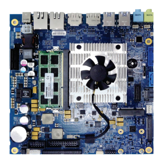
Doc. Rev. 1.2 mITX-APL 3/ Installation procedure 3.1. Packing Check List The mITX-APL package includes the following basic items accompany with this manual. One mainboard One IO shield Figure 1: Mainboard mITX-APL Figure 2: IO Shield (pattern) If any of these items is damaged or missed, please contact your vendor and save all packing materials for future replacement and maintenance. -
Page 15: Requirements Iec60950-1
Doc. Rev. 1.2 mITX-APL To get the board running follow these steps. If the board shipped from Kontron has already components like RAM and CPU cooler mounted, then relevant steps below can be skipped. Turn off the PSU (Power Supply Unit) Turn off PSU (Power Supply Unit) completely (no mains power connected to the PSU) or leave the Power Connectors unconnected while configuring the board. -
Page 16: Lithium Battery Precautions
Doc. Rev. 1.2 mITX-APL 3.4. Lithium battery precautions Danger of explosion if the lithium battery is incorrectly replaced. • Replace only with the same or equivalent type recommended by the manufacturer • Dispose of used batteries according to the manufacturer’s instructions VORSICHT! Explosionsgefahr bei unsachgemäßem Austausch der Batterie. -
Page 17: 4/ System Specifications
DDR3L, 4 GB 1867MHz, PC3-1867, non-ECC, E2 SODIMM DDR3L, 8 GB 1867MHz, PC3-1867, non-ECC, E2 SODIMM The mITX-APL supports embedded embedded Multimedia Card (eMMC) interface 5.0 with a Flash Memory maximum bus speed of 400 MB/s. The board will also support a SD card interface UHS-I standard with a maximum bus speed of 104 MB/s. - Page 18 Doc. Rev. 1.2 mITX-APL one PCI-Express 2.0 x1 Slot Expansion one mPCIe/ mSATA with USB/UIM SIM interface Six different Board Support Packages are offered: Operating System Support BSP1: Windows 10 IOT Enterprise 64 bit, eMMC Boot ...
- Page 19 Rise Time specification 2 to 20ms from input voltage <10% to nominal VCC The mITX-APL is operated by a single 12 to 24 V wide Input Voltage (VIN) DC supply from DC External Power Jack on rear I/O Singatron 2DC1003-010111 or optionally 12 V DC supply through an internal Supply ATX 4-pin header.
-
Page 20: Environmental Conditions
PSD: 10-20Hz: 0.05 g²/Hz and 20-500Hz:- 3dB/octave. Theoretical MTBF 1,073,767 to 1,454,122 hours depending on processor type at 30° C for the mITX-APL Restriction of The product will comply to the European Council Directive on the approximation of the laws Hazardous of the member states relating to Directive 20011/65/EU or the last status thereof. -
Page 21: Block Diagram
Doc. Rev. 1.2 mITX-APL 4.3. Block Diagram Figure 3: Block Diagram of mITX-APL www.kontron.com // 21... -
Page 22: 5/ Jumpers And Connectors
Doc. Rev. 1.2 mITX-APL 5/ Jumpers and Connectors 5.1. Hardware Configuration Setting This chapter gives the definitions and shows the positions of jumpers, headers and connectors. All of the configuration jumpers on the board are in the proper position. The default settings shipped from factory are marked with an asterisk (*). -
Page 23: Mainboard Placement And Rear I/O Locations
Doc. Rev. 1.2 mITX-APL 5.2. Mainboard Placement and Rear I/O locations Figure 4: Front Side and Interfaces LVDS connector 17 two Display Ports CPU and Sys Fan connector 18 two Ethernet Ports GPIO (44-Pin connector) 19 Power connector Memory with connector... -
Page 24: Inferfaces
Doc. Rev. 1.2 mITX-APL 5.2.1. Inferfaces Figure 5: Interfaces For the numbers look at page 23. 5.2.2. Rear Side Figure 6: Rear Side 31 MicroSIM/MicroSD Combo adapter 32 eMMC controller www.kontron.com // 24... -
Page 25: 6/ Pin Definitions
Doc. Rev. 1.2 mITX-APL 6/ Pin Definitions The following sections provide pin definitions and detailed description of all on-board connectors. The connector definitions follow the following notation: Table 5: Connector Definitions Column Name Description Shows the pin-numbers in the connector. The graphical layout of the connector definition tables is made similar to the physical connectors. -
Page 26: Processor Support
Intel® Atom™ x5 E3930 2C 1.8 GHz, 6.5 W Intel® Mobile Celeron® N3350 2C 2.3 GHz, 6 W Kontron has defined the board versions as listed in the following table, so far all based on Embedded CPUs. Table 6: Processor Support Name... -
Page 27: Flash Memory
Doc. Rev. 1.2 mITX-APL 6.3. Flash Memory The mITX-APL supports eMMC interface 5.0 with a maximum bus speed of 400 MB/s. The board will also support a SD card interface UHS-I standard with a maximum bus speed of 104 MB/s. ... -
Page 28: Usb Connectors (I/O Area)
Doc. Rev. 1.2 mITX-APL 6.5. USB Connectors (I/O area) Figure 9: USB 2.0 / 3.0 socket USB 2.0 USB 3.0 Table 7: Pin Assignment Type Signal Note 5 V / SB 5 V USB2.0 / 3.0 USB 3- USB2.0 / 3.0 USB 3+ USB2.0 / 3.0... -
Page 29: Dc Power-Jack Connector J56
Doc. Rev. 1.2 mITX-APL For USB3.0 cabling it is required to use only HiSpeed USB cable, specified in USB3.0 standard: Figure 11: USB 3.0 High Speed Cable UTP Signal Pair Filler, optional SDP Signal Pair Braid Jacket Power SDP Signal Pair Ground 6.6. -
Page 30: Audio Jack Connectors (I/O Area)
Doc. Rev. 1.2 mITX-APL 6.7. Audio Jack Connectors (I/O area) Figure 13: Audio Jacks Table 10: Pin Assignment (Line Out, green, Figure 13 left ) Signal Lineout_Rear_L/Headphone_L Lineout_Rear_JD Lineout_Rear_R/Headphone_R Table 11: Pin Assignment (Line In, blue, Figure 13 right) Signal... -
Page 31: Front Panel 1 (Internal)
Doc. Rev. 1.2 mITX-APL Signal Description Type Fan speed control. Table 13: Signal Description Signal Description Type Power Supply GND signal 12 V +12 V supply for fan. A maximum of 2000 mA can be supplied from this pin. TACHO Tacho input signal from the fan, for rotation speed supervision RPM (Rotations Per Minute). -
Page 32: Rs232 Header (Internal)
Doc. Rev. 1.2 mITX-APL 6.10. RS232 Header (internal) Figure 16: 2-wire RS232 Table 15: RS232 Header Description Description NSIN NSOUT Table 16: Signal Description Signal Description NSIN User Input NSOUT User Output Ground Figure 17: Available Cable Kit (DB9 adapter cables) 6.11. -
Page 33: Feature Connector
Doc. Rev. 1.2 mITX-APL Description TX1+ RX1- 6.12. Feature Connector Figure 19: Internal Feature Connector (2x22 pins) Table 18: Feature Connector Description Description SMBC SMBD PWR_OK EXT_BAT SB3V3 SB5V GPIO0 GPIO1 GPIO2 GPIO3 GPIO4 GPIO5 GPIO6 GPIO7 GPIO8 GPIO9 GPIO10... -
Page 34: Cmos1 Internal
Doc. Rev. 1.2 mITX-APL 6.13. CMOS1 Internal Figure 20: CMOS1 Internal Connector Table 19: CMOS1 Internal Connection Description RTCRST# 6.14. SPK Internal Figure 21: SPK Internal Connector Table 20: SPK Internal Connection Description HP Left HP Right 6.15. MIC1 Connector (J22) The MIC1 interface is available through the connector J22 (four pins). -
Page 35: Spdif-Out Connector (J25)
Doc. Rev. 1.2 mITX-APL Table 21: Pin Assignment Signal Type MIC1_L_Header MIC1_R_Header 6.16. SPDIF-OUT Connector (J25) The digital audio interface (electrical SPDIF-Out) is available through the 2-pin connector J25 and can be used to implement 6 (5.1) Channel High Definition Audio. Circuit is based on high fidelity 6-channel HD audio codec which is compatible with Intel HD Audio specification and supports stereo 24-bit resolution and up to 192 kHz sample rate for DACs/ADCs. -
Page 36: Sata (Serial Ata) Disk Interfaces (Internal)
Doc. Rev. 1.2 mITX-APL Description Description LVDS A0- LVDS A0+ LVDS A1- LVDS A1+ LVDS A2- LVDS A2+ LVDS ACLK- LVDS ACLK+ LVDS A3- LVDS A3+ LVDS B0- LVDS B0+ LVDS B1- LVDS B1+ LVDS B2- LVDS B2+ LVDS BCLK-... -
Page 37: Sata Power Connector (J14)
Doc. Rev. 1.2 mITX-APL Figure 26: Available Cable Kit 6.19. SATA Power Connector (J14) Figure 27: SATA Power Connector Table 26: Pin Assignment Signal Description Type +5VS Power +5V Ground Ground +12VS Power +12V 6.20. Display Port The two external Display Port 1.2 at rear I/O space are supporting Active/Passive HDMI 1.4a and DVI adapters. -
Page 38: Dc Power Connector
Doc. Rev. 1.2 mITX-APL Signal Description ML_Lane 2 (p) Lane 2 (positive) Ground ML_Lane 2 (n) Lane 2 (negative) ML_Lane 3 (p) Lane 3 (positive) Ground ML_Lane 3 (n) Lane 3 (negative) CONFIG1 connected to Ground CONFIG2 Connected to Ground... -
Page 39: Table 29: Pin Assignment
Doc. Rev. 1.2 mITX-APL Table 29: Pin Assignment Signal Type SB3V3 CS0# ADDIN 3V3_SPI MOSI ISOLATE# MISO Table 30: Signal description Signal Description Serial Clock SB3V3/3V3_SPI 3.3 V Standby Voltage power line. Normally output power, but when Motherboard is turned off then the on-board SPI Flash can be 3.3 V power sourced via this pin. -
Page 40: Combo Connector For Microsd And Microsim
6.23. Combo Connector for MicroSD and MicroSIM The mITX-APL supports eMMC interface 5.0 with a maximum bus speed of 400 MB/s. The board will also support a SD card interface UHS-I standard with a maximum bus speed of 104 MB/s. -
Page 41: Slot Connector (Mpcie/Msata) (J29)
Doc. Rev. 1.2 mITX-APL 6.24. Slot Connector (mPCIe/mSATA) (J29) The Slot connector has two functions: mSATA or miniPCIe. The Slot connector detects the mounted card technology with autosensing. So there is no need for further configuration. mSATA functionality is multiplexed with right angle SATA connector (J16). You can only use... - Page 42 Doc. Rev. 1.2 mITX-APL Signal Type +3V3 PCIE_RX+/SATA_RX+ +1.5 V SMB_CLK PCIE_TX-/SATA_TX- SMB_DATA PCIE_TX+/SATA_TX+ USBhub_D1_N USBhub_D1_P +3V3 +3V3 SATA_DET5# +1.5 V +3V3 www.kontron.com // 42...
-
Page 43: Pcie X1 Connector (J17)
Doc. Rev. 1.2 mITX-APL 6.25. PCIe x1 Connector (J17) Figure 33: PCIe x1 Connector Table 34: PCIe x1 Side B Connector Side A Connector Name Description Name Description +12v +12 volt PRSNT#1 Hot plug power presence detect +12v +12 volt... -
Page 44: Rtc/Clear Cmos
Doc. Rev. 1.2 mITX-APL 6.26. RTC/Clear CMOS Table 35: RTC/Clear CMOS Configurations RTC_RST# / RTC_TEST# DIS_SECCMOS State PIN 2 - 3 (open) PIN 2 - 3 (open) Default state PIN 1 - 2 (short) PIN 1 - 2 (short) clear... -
Page 45: 7/ Uefi Bios
7/ uEFI BIOS 7.1. Starting the uEFI BIOS The pITX-APL is provided with a Kontron-customized, pre-installed and configured version of American Megatrends, Inc. (AMI). It is based on the Unified Extensible Firmware Interface (uEFI) specification and the Intel® Platform Innovation Framework for EFI. This uEFI BIOS provides a variety of new and enhanced functions specifically tailored to the hardware features of the pITX-APL. -
Page 46: Setup Menus
Doc. Rev. 1.2 mITX-APL 7.2. Setup Menus The Setup utility features a selection bar at the top of the screen that lists the available menus: Main Advanced Chipset Security Boot Save & Exit The currently active menu and the currently active uEFI BIOS Setup item are highlighted in white. Use the left and right arrow keys to select the Setup menus. -
Page 47: Table 37: Main Setup Menu Sub-Screens
Doc. Rev. 1.2 mITX-APL Table 37: Main Setup Menu Sub-screens Sub-Screen Function Second level Sub-Screen / Description Read only field BIOS Displays BIOS Information Information Board Vendor, BIOS Version, Build Date and Time, Access Level Read only field Board Displays Board Information... -
Page 48: Advanced Setup Menu
7.2.2. Advanced Setup Menu The Advanced Setup menu provides sub-screens and second level sub-screens with functions, for advanced configuration and Kontron specific configurations. Setting items, on this screen, to incorrect values may cause system malfunctions. Figure 35: Advanced Setup Menu Initial Screen The following table shows the Advanced sub-screens and functions and describes the content. -
Page 49: Table 38: Advanced Setup Menu Sub-Screens And Functions
Doc. Rev. 1.2 mITX-APL Table 38: Advanced Setup menu Sub-screens and Functions Sub-Screen Function Second level Sub-Screen / Description Intel® PRO/1000 7.0.06 PCI-E Driver Health When set to Enable: Active PCR banks Available PCR banks SHA-1 PCR Bank [Enabled] TPM20 Device Status,... - Page 50 Doc. Rev. 1.2 mITX-APL Sub-Screen Function Second level Sub-Screen / Description Parity [None] Stop Bits [1] Turbo Mode [Enabled] Intel Virtualization Technology [Enabled] Configurati VT-d [Disabled] Monitor Mwait [Disabled] AMI Graphic Intel ® Graphics Controller Output Intel ® GOP Driver...
- Page 51 Doc. Rev. 1.2 mITX-APL Sub-Screen Function Second level Sub-Screen / Description When set to Enabled: Panel Type [Standard] Resolution [1024 x 768] Panel Color Depth [24-Bit VESA] Panel Voltage [3.3V] LVDS Channel [Dual] LVDS Flat Panel Display Configurati Support [Disabled]...
- Page 52 Doc. Rev. 1.2 mITX-APL Sub-Screen Function Second level Sub-Screen / Description DDR SSC Bending Selection Table [0% (No Clock Bending)] When set to Enable: HighSpeed SerialIO SSC [Enable] HighSpeed SerialIO SSC Selection Table [-0.5%] Kernel Debugger Configuration Kernel Debugger Enable [Disabled]...
-
Page 53: Chipset Setup Menu
Doc. Rev. 1.2 mITX-APL Sub-Screen Function Second level Sub-Screen / Description Punit Message Level [LEVEL LOW] PMC Message Level [LEVEL LOW] Native PCIE Enable [Enable] RC ACPI Settings Native ASPM [Enable] RTD3 RTD3 Support [Disable] Settings 7.2.3. Chipset Setup Menu The Chipset Setup menu provides sub-screens, second level and third level sub-screens with functions, for Intel Chipset configurations. - Page 54 Doc. Rev. 1.2 mITX-APL Sub-Screen Function Second level Sub-Screen / Description OS Selection [Windows 10 (Ver>=167)] PCI Clock Run [Enable] Real Time Option [RT Disable] GOP Configuration Uncore GOP Driver [Enable] Configuration Intel Graphics Pei Display PEIM [Disable] GOP Brightness Level [140]...
- Page 55 Doc. Rev. 1.2 mITX-APL Sub-Screen Function Second level Sub-Screen / Description PCH PCIE LTR [Enable] Snoop Latency Override [Auto] Non Snoop Latency Override [Auto] PCIE LTR Lock [Disable] PCIE Selectable De-emphasis [Enable] SATA Drives Chipset-SATA Controller Configuration SATA Port 0...
-
Page 56: Security Setup Menu
Linux boot loader signed with Microsoft’s platform key. Select “Customized” mode only if you have a custom OS with OS boot loader signed with your own platform key. Kontron provide services for Customized Secure Boot, visit Kontron SEC-Line home www.kontron.com... -
Page 57: Remember The Password
It is highly recommended to keep a record of all passwords in a safe place. Forgotten passwords result in the user being locked out of the system. If the system cannot be booted because the User Password or the Supervisor Password are not known, contact Kontron Support for further assistance. www.kontron.com // 57... -
Page 58: Boot Setup Menu
Doc. Rev. 1.2 mITX-APL 7.2.6. Boot Setup Menu The Boot Setup menu lists dynamically generated boot device priority order. Figure 38: Boot Setup Menu Initial Screen The following table shows Boot sub-screens and functions, and describes the content. Default settings are in bold. -
Page 59: Exit Setup Menu
Doc. Rev. 1.2 mITX-APL Function Description PS2 Support Network Stack Driver Support Redirection Support New Boot Option Policy Controls the placement of newly detected UEFI boot options Hard Drive BBS Priotities Sets the placement of legacy boot options 7.2.7. Exit Setup Menu The Save and Exit Setup menu provides functions for handling changes made to the uEFI BIOS settings and exiting the Setup program. -
Page 60: The Uefi Shell
7.3. The uEFI Shell The Kontron uEFI BIOS features a built-in and enhanced version of the uEFI Shell. For a detailed description of the available standard shell scripting, refer to the EFI Shell User Guide. For a detailed description of the available standard shell commands, refer to the EFI Shell Command Manual. -
Page 61: Exiting The Uefi Shell
Initially searches for Kontron flash-stored startup script. If there is no Kontron flash-stored startup script present then the uEFI-specified startup.nsh script is used. This script must be located on the root of any of the attached FAT formatted disk drive. - Page 62 Doc. Rev. 1.2 mITX-APL Change to the drive representing the USB stick. fsx: (x = 0,1,2,etc. represents the USB stick) Change to the directory where you copied the flash tool. cd <your_directory> Start flash.nsh or flash_with_fpt.nsh (if available) OR type fpt –y –f pITX_APL_BIOS_Ver_<xxx>……bin...
-
Page 63: List Of Acronyms
Doc. Rev. 1.2 mITX-APL List of Acronyms Board Support Packages Display Port Error Checking and Correction Embedded Display Port GPIO General Purpose In-Output mITX Mini ITX PCIe PCI-Express Real Time Clock SKUs Stockkeeping Units Serial Peripheral Interface Trusted Platform Module www.kontron.com... -
Page 64: About Kontron
About Kontron Kontron, a global leader in embedded computing technology and trusted advisor in Internet of Things (IoT), works closely with its customers, allowing them to focus on their core competencies by offering a complete and integrated portfolio of hardware, software and services designed to help them make the most of their applications.
Need help?
Do you have a question about the mITX-APL and is the answer not in the manual?
Questions and answers