Table of Contents
Advertisement
Quick Links
Advertisement
Table of Contents

Related Manuals for Kontron mITX-BW


Summary of Contents for Kontron mITX-BW
- Page 1 USER GUIDE mITX-BW Doc. User Guide, Rev. 1.6 Doc. ID: 1060-7044...
- Page 2 Kontron products. This document does not entail any guarantee on the part of Kontron with respect to technical processes described in the manual or any product characteristics set out in the manual. Kontron assumes no responsibility or liability for the use of the described product(s), conveys no...
- Page 3 ENVIRONMENTAL DAMAGE (COLLECTIVELY, "HIGH RISK APPLICATIONS"). You understand and agree that your use of Kontron devices as a component in High Risk Applications is entirely at your risk. To minimize the risks associated with your products and applications, you should provide adequate design and operating safeguards.
- Page 4 If you have any difficulties using this user guide, discover an error, or just want to provide some feedback, contact Kontron support. Detail any errors you find. We will correct the errors or problems as soon as possible and post the revised user guide on our website.
-
Page 5: Symbols
– User Guide, Rev. 1.6 Symbols The following signs and symbols may be used in this User Guide: DANGER indicates a hazardous situation which, if not avoided, will result in death or serious injury. WARNING indicates a hazardous situation which, if not avoided, could result in death or serious injury. - Page 6 Therefore, in the interest of your own safety and of the correct operation of your new Kontron product, you are requested to conform with the following guidelines.
- Page 7 General Instructions on Usage In order to maintain Kontron’s product warranty, this product must not be altered or modified in any way. Changes or modifications to the product, that are not explicitly approved by Kontron and described in this User Guide or received from Kontron’s Technical Support as a special handling instruction, will void your warranty.
-
Page 8: Table Of Contents
– User Guide, Rev. 1.6 Table of Contents Symbols ..........................................5 Table of Contents ......................................8 List of Tables ........................................10 List of Figures ........................................11 1/ Introduction ......................................... 12 2/ Installation procedure ..................................... 13 2.1. Installing the Board ....................................13 2.2. - Page 9 – User Guide, Rev. 1.6 7.20. Micro SD Card Connector (J45) ................................. 52 7.21. SIM Card connector (J31) ..................................52 8/ On-Board Connectors & Mating Connector Types ........................53 9/ BIOS ..........................................54 9.1. Starting the uEFI BIOS ..................................... 54 9.2.
-
Page 10: List Of Tables
– User Guide, Rev. 1.6 List of Tables Table 1: Component Main Data ..................................15 Table 2: Environmental Conditions ................................17 Table 3: Processor Support ................................... 19 Table 4: Memory Operating Frequencies ..............................20 Table 5: Three-displays Configurations ..............................21 Table 6: Supply Voltages.................................... -
Page 11: List Of Figures
– User Guide, Rev. 1.6 List of Figures Figure 1: Block Diagram ....................................18 Figure 2: DP Adapters ...................................... 21 Figure 3: Reaktek HD Audio Manger- Device Advanced Settings ....................22 Figure 4: Windows Sound Manager- Recording FrontMic Settings ....................22 Figure 5: Windows Sound Manager- Recording Microphone Settings .................. -
Page 12: 1/ Introduction
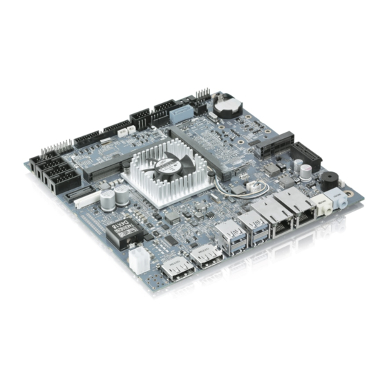
– User Guide, Rev. 1.6 1/ Introduction This User Guide describes the mITX-BW board made by Kontron AG. This board will also be denoted mITX-BW within this Users Guide. The mITX-BW board is based on the Intel® Braswell Celeron processors, N3xxx series. See “Processor Support Table”... -
Page 13: 2/ Installation Procedure
• Handle the board only by the edges To get the board running follow these steps. If the board shipped from KONTRON has already components like RAM and CPU cooler mounted, then relevant steps below can be skipped. Turn off the PSU (Power Supply Unit) Turn off PSU (Power Supply Unit) completely (no mains power connected to the PSU) or leave the Power Connectors unconnected while configuring the board. -
Page 14: Requirements Iec60950-1
When fixing the Motherboard on a chassis it is recommended using screws with integrated washer and a 2.2. Requirements IEC60950-1 Take care when designing chassis interface connectors in order to fulfil the IEC60950-1 standard. Users of mITX-BW must evaluate the end product to ensure compliance the requirements of the IEC60950-1 safety standard are met: ... -
Page 15: 3/ System Specifications
– User Guide, Rev. 1.6 3/ System specifications 3.1. Component Main Data The table below summarizes the features of the mITX-BW embedded motherboard. Table 1: Component Main Data Form factor mITX-BW: miniITX (170.18 mm by 170.18 mm) Processor On board CPU variants support Intel® Atom™ (Braswell) processors in a Multi-chip package with the PCH (max. - Page 16 – User Guide, Rev. 1.6 Expansion 1x mPCIe connector with USB 2.0 port support for 3G modem (SIM socket) as well Capabilities as MSATA 1x μSD card connector 1x eMMC module option SMBus, compatible with ACCES BUS and I2C BUS, (via Feature connector) SPI bus routed to SPI connector (BIOS Recovery module interface) ...
-
Page 17: Table 2: Environmental Conditions
-20 °C to +70 °C; lower limit of storage temperature is defined by specification restriction of on-board CR2032 battery. Board with battery has been verified for storage temperature down to -40 °C by Kontron. 5% to 95% relative humidity (non-condensing) Radiated Emissions All Peripheral interfaces intended for connection to external equipment are EMI protected. -
Page 18: Mitx Block Diagram
– User Guide, Rev. 1.6 3.2. mITX Block Diagram Figure 1: Block Diagram www.kontron.com // 18... -
Page 19: Processor Support Table
3.3. Processor Support Table mITX-BW is designed to support the Braswell Celeron processors. The BGA CPU is premounted from factory. Kontron has defined the board versions as listed in the following table, so far all based on Embedded CPUs. Other versions are expected at a later date. -
Page 20: System Memory Support
EOL module will be replaced by other similar type of qualified module. As a minimum it is recommend using Kontron memory modules for prototype system(s) in order to prove stability of the system and as for reference. -
Page 21: Mitx-Bw Graphics Subsystem
– User Guide, Rev. 1.6 3.5. mITX-BW Graphics Subsystem The mITX-BW equipped with Intel ® Celeron processor, supports Intel ® Gen 8 HD Graphics core. All mITXBW versions support three displays pipes. The DP interface supports the DisplayPort 1.2a specification. The PCH supports High- bandwidth Digital Content Protection for high definition content playback over digital interfaces. -
Page 22: Audio
– User Guide, Rev. 1.6 3.5.1. Audio The PCH integrates audio Codecs for audio support. To set the HDA Codec in the Windows environment, install the ALC886 driver. The Realtek HD Audio Manager will be located in the Control Panel. Implement the following steps to set the Realtek HD Audio Manger. -
Page 23: Power Consumption
ATX power supplies, which require a minimum load to stay in regulation. The mITX-BW board must be powered through either the ATX+12V-4p (4-pole) connector using standard ATX power supply or by an external 12 to 24V power adapter through the Rear I/O power jack. -
Page 24: 4/ Connector Locations
– User Guide, Rev. 1.6 4/ Connector Locations 4.1. mITX-BW Front Side Figure 6: Front Side www.kontron.com // 24... -
Page 25: Table 8: Items On Front Side Of Board
– User Guide, Rev. 1.6 Table 8: Items on Front Side of Board Item Desig. Description See section LPC Connector (Low Pin Count, Serial bus) 7.18 Feature Connector 7.14 RS485 connector “ALWAYS ON“ Jumper 7.16 PS/2 Keyboard and Mouse Connector (KBDMSE) FRONTPNL Connector 7.11... -
Page 26: Table 9: Items On Rear Side Of Board
– User Guide, Rev. 1.6 Figure 7: Rear Side Table 9: Items on Rear Side of Board Item Desig. Description See section Micro SD Card Connector SIM Card Connector 7.21 www.kontron.com // 26... -
Page 27: 5/ Connector Definitions
– User Guide, Rev. 1.6 5/ Connector Definitions The following sections provide pin definitions and detailed description of all on-board connectors. The connector definitions follow the following notation: Table 10: Connector definitions Column Name Description Shows the pin-numbers in the connector. The graphical layout of the connector definition tables is made similar to the physical connectors. -
Page 28: 6/ Io-Area Connectors
– User Guide, Rev. 1.6 6/ IO-Area Connectors 6.1. DP Connectors DP1 and DP2 (J19 & J16) The DP (DisplayPort) connectors are based on standard DP type Foxconn 3VD51203-H7JJ-7H or similar. DP to DVI dongle Digital Visual Inteface (DVI) dongle is only supported on DP1. -
Page 29: Ethernet Connectors (J26 & J28)
– User Guide, Rev. 1.6 6.2. Ethernet Connectors (J26 & J28) The mITX-BW supports two channels of 10/100/1000 Mbit Ethernet, one (LAN1) is based on Intel® Pearsonville i211AT PCI Express controller. In order to achieve the specified performance of the Ethernet port, Category 5 twisted pair cables must be used with 10/100 MByte and Category 5E, 6 or 6E with 1 Gbit LAN networks. -
Page 30: Usb Connectors /Io Area (J21 & J23)
USB 2.0 Ports 5, 6 are supplied on the combined Front Panel connector (J4). USB 2.0 Port 4 is available in the mPCIe connector (J35). Enhanced Host Controlled Interface (EHCI) is not supported by the mITX-BW Board. The mITX-BW board only support XHCI. Figure 10: USB 2.0 / 3.0 socket J21, J23 USB 2.0... -
Page 31: Figure 11: Usb 2.0 High Speed Cable
– User Guide, Rev. 1.6 For USB2.0 cabling it is required to use only HiSpeed USB cable, specified in USB2.0 standard: Figure 11: USB 2.0 High Speed Cable Polyvinyl Chloride (PVC) Jacket On-Twisted Power Pair: Red: V Black: Power Ground... -
Page 32: Audio Jack Connectors (J3 & J11)
– User Guide, Rev. 1.6 6.4. Audio Jack Connectors (J3 & J11) Figure 13: Audio Jack Connectors J3, J11 Ring J3, Line OUT Sleeve J11,Line IN Mating Audio Jack (example) Table 16: Pin Assignment J3 (Line Out, green) Pin Designation... -
Page 33: 7/ Internal Connectors
– User Guide, Rev. 1.6 7/ Internal Connectors 7.1. Power Connectors Either the DC Power Jack Connector “EXT12 V” or the “Int12 V.” connector must be used to supply the board with +12 (-10%) to +24 VDC (+10%). Hot plugging any of the power connectors (J40 and J56) is not allowed. -
Page 34: Dc Power-Jack Connector (J56)
– User Guide, Rev. 1.6 7.1.2. DC Power-Jack Connector (J56) Figure 15: Power Connector J56 Table 20: Pin Assignment J56 Pin Designation Signal Description Type Center Power +12 V to +24 V (2.5 mm Center Pin) Ring Ground (5.5 mm Ring hole) The board can be supplied via the AC/DC adapter plugged into the power jack. -
Page 35: Ps/2 Keyboard And Mouse Connector (Kbdmse) (J15)
– User Guide, Rev. 1.6 Signal Description Type TACHO Tacho signal Not used Table 23: Signal description Signal Description Type Power Supply GND signal 12 V +12 V supply for fan. A maximum of 2000 mA can be supplied from this pin. -
Page 36: Sata (Serial Ata) Disk Interfaces (J39 & J8)
7.4. SATA (Serial ATA) Disk Interfaces (J39 & J8) The mITX-BW has an integrated SATA Host controller (PCH in the BW chipset) that supports independent DMA operation on two ports. One device can be installed on each port for a maximum of two SATA devices via two SATA connectors and one mSATA/mPCIe connector. -
Page 37: Sata Power Connector (J5)
– User Guide, Rev. 1.6 Table 26: Pin Assignment J39, J8 Signal Type Ioh / Iol Note SATA* TX+ SATA* TX- SATA* RX- SATA* RX+ Table 27: Signal description Signal Description SATA* RX+ / RX- Host transmitter differential signal pair... -
Page 38: Usb Connectors /Internal
– User Guide, Rev. 1.6 Table 29: Pin Assignment J50 Signal Description Type Ground RS485_DATA- Data Low IO 12.0 RS485_DATA+ Data High IO 12.0 7.7. USB Connectors /Internal The following USB2.0 ports are available on Internal pinrows: USB2.0 Ports 5, 6 are supplied on the internal FRONTPNL connector (J4). -
Page 39: Spdif-Out Connector (J9)
– User Guide, Rev. 1.6 Table 31: Pin Assignment J2 Signal Type Note MIC1_L_Header MIC1_R_Header 7.10. SPDIF-OUT Connector (J9) The digital audio interface (electrical SPDIF-Out) is available through the 2 pin connector J9 and can be used to implement 6 (5.1) Channel High Definition Audio. Circuit is based on high fidelity 6-channel HD audio codec which is compatible with Intel HD Audio specification and supports stereo 24-bit resolution and up to 192 kHz sample rate for DACs/ADCs. -
Page 40: Table 34: Signal Description
– User Guide, Rev. 1.6 Signal Type Ioh / Iol Pull U / D Note USBhub_D2+ USBhub_D3+ LINE2-L +5 V +5 V SATA_LED# 25 / 25 mA SUS_LED 7 mA PWRBTN_IN# 1.1 kΩ RSTIN# 4.7 kΩ SB3V3 LINE2-R AGND... -
Page 41: Serial Com1 - Com4 Ports (J20, J18, J22, J27)
– User Guide, Rev. 1.6 Figure 27: Available Cable Kit: PN 821042 Cable Front Panel Open-End, 300 mm 7.12. Serial COM1 – COM4 Ports (J20, J18, J22, J27) Figure 28: Serial COM J20, J18, J22, J27 Table 35: Pin Assignment J20, J18, J22, J27... -
Page 42: Lvds Flat Panel Connector (J29)
– User Guide, Rev. 1.6 Table 36: Signal description Signal Description Transmitted Data, sends data to the communications link. The signal is set to the marking state (-12 V) on hardware reset when the transmitter is empty or when loop mode operation is initiated. -
Page 43: Table 38: Signal Description
LVDS Max. 0.5 A Max. 0.5 A The mITX-BW on-board LVDS connector supports single and dual channel, 18/24 bit SPWG panels up to a resolution of 1600x1200 px or 1920x1080 px and with limited frame rate up to 1920x1200 px. -
Page 44: Feature Connector (J13)
– User Guide, Rev. 1.6 Signal Description Power sequencing depends on LVDS panel selection. (Shared with eDP connector) DDC CLK DDC Channel Clock Windows API will be available to operate the BKLTCTL signal. Some Inverters have a limited voltage range 0- 2.5V for this signal: If voltage is > 2.5V the Inverter might latch up. Some Inverters generate noise on the BKLTCTL signal, causing the LVDS transmission to fail (corrupted picture on the display). -
Page 45: Table 40: Signal Description
– User Guide, Rev. 1.6 Signal Type Ioh / Iol Pull U / D Note GPIO8 GPIO9 GPIO10 GPIO11 GPIO12 GPIO13 GPIO14 GPIO15 GPIO16 GPIO17 EGCLK 8 / 8 mA EGCS# 8 / 8 mA EGAD 8 / 8 mA... -
Page 46: Table 41: Signal Description It 8528E Embedded Controller
– User Guide, Rev. 1.6 The GPIO’s are controlled via the ITE IT8528E Embedded Controller. Each GPIO has 100pF to ground, clamping Diode to 3V3 and has multiplexed functionality. Some pins can be DAC (Digital to Analogue Converter output), PWM (Pulse Width Modulated signal output), ADC (Analogue to Digital Converter input), TMRI (Timer Counter Input), WUI (Wake Up Input), RI (Ring Indicator Input) or some special function. -
Page 47: Load Default Bios Settings Jumper (J44)
– User Guide, Rev. 1.6 Figure 32: Available cable kit, Break-Out-Board: PN 1052-5885 Cable, Feature 44pol 1 to1, 300 mm PN 820978 Feature BOB (Break-Out-Board) 7.15. LOAD DEFAULT BIOS SETTINGS Jumper (J44) The “Load Default BIOS Settings” Jumper (J44) can be used to recover from incorrect BIOS settings. -
Page 48: Spi Connector (J6)
– User Guide, Rev. 1.6 7.17. SPI Connector (J6) The SPI Connector is normally not used. If however a SPI BIOS is connected via the SPI Connector then the board will attempt to boot from it. Figure 35: SPI Connector (pinheader 10x) J6... -
Page 49: Lpc Connector (J7)
– User Guide, Rev. 1.6 7.18. LPC Connector (J7) The LPC connector is in general unsupported. Only under special circumstances may the LPC interface be of interest. Figure 36: LPC Connector (pinheader 20x) J7 18 20 Table 45: Pin Assignment J7... -
Page 50: Slot Connectors (Mpcie) (J35)
– User Guide, Rev. 1.6 7.19. Slot Connectors (mPCIe) (J35) MiniPCIe with mSATA/USB2.0 & SIM-card support (J35). Slot J35 supports mPCIe, USB2.0 and SIM-card socket The SIM-card socket makes it possible to use a 2G/3G-wireless modem in this mPCIe slot. - Page 51 – User Guide, Rev. 1.6 Signal Type Ioh / Iol Pull U / D Note +3V3 +3V3 SATA_DET5# +1.5 V +3V3 www.kontron.com // 51...
-
Page 52: Micro Sd Card Connector (J45)
– User Guide, Rev. 1.6 7.20. Micro SD Card Connector (J45) Figure 37: Micro SD Card Connector on rear side of board (selection) Table 47: Pin Assignment J45 Signal Description Type SD3_D2 Data bit 2 IO 3.3/1.8 SD3_D3 Card Detect / Data bit 3 IO 3.3/1.8... -
Page 53: 8/ On-Board Connectors & Mating Connector Types
The mating connectors / cables are connectors or cable kits that fit the on-board connector. The Kontron cable kits marked with “*” are included in the “mITX-BW Cable & Driver Kit” PN 826603. Table 49: On-Board Connectors, Mating Connector Types... -
Page 54: 9/ Bios
Supervisor Password (see Security menu), press <RETURN>, and proceed with step 5. A Setup menu will appear. The mITX-BW uEFI BIOS Setup program uses a hot key-based navigation system. A hot key legend bar is located on the bottom of the Setup screens. -
Page 55: Setup Menus
– User Guide, Rev. 1.6 9.2. Setup Menus The Setup utility features four menus listed in the selection bar at the top of the screen: Main Advanced Chipset Security Boot Save & Exit The Setup menus are selected via the left and right arrow keys. -
Page 56: Advanced Setup Menu
– User Guide, Rev. 1.6 9.2.2. Advanced Setup Menu The Advanced Setup menu provides sub-screens and functions for advanced configuration. Setting items on this screen to incorrect values may cause the system to malfunction. Table 52: Advanced Setup Menu Sub-Screens and Functions... - Page 57 – User Guide, Rev. 1.6 Sub-Screen Funtion Description Serial Port Console COM0 Enable/Disable COM0 Console Redirection Redirection Console Redirection COM0 Setting for COM0 Console Redirection Console Redirection Setting COM1 Enable/Disable COM1 Console Redirection Console Redirection COM1 Setting for COM1 Console Redirection...
- Page 58 – User Guide, Rev. 1.6 Sub-Screen Funtion Description Intel Virtualization Enable/Disable Intel Virtualization Technology Technology Power Technology Enable/Disable Power Technology EIST Enable/Disable EIST Turbo Mode Enable/Disable Turbo Mode P-STATE Coordination Select the type of P-STATE Package C State limit Select the C state limit...
- Page 59 – User Guide, Rev. 1.6 Sub-Screen Funtion Description eMMC Secure Erase Disable/Enable eMMC Secure Erase SCC SDIO Support Select SCC SDIO Support (D17:F0) PCI or ACPI (D17:F0) SCC SD Card Support Enable\Disable SCC SD Card Support (D18:F0) (D18:F0) eMMC RX DLL Tuning...
- Page 60 – User Guide, Rev. 1.6 Sub-Screen Funtion Description PCI Subsystem PCI Latency Timer Value to be programmed into PCI Latency Timer Register Settings PCI-X Latency Timer Value to be programmed into PCI-XLatency Timer Register VGA Palette Snoop Enable\Disable VGA Palette Registers Snooping...
-
Page 61: Chipset Setup Menu
– User Guide, Rev. 1.6 Sub-Screen Funtion Description Platform Trust fTPM Enable\Disable fTPM Technology Security TXE HMRFPO Enable\Disable TXE HMRFPO Configuration TXE Firmware Update Enable\Disable TXE Firmware Update TXE EOP Message Enable\Disable TXE EOP Message IntelRMT Intel RMT Support... -
Page 62: Remember The Password
If the system cannot be booted because neither the User Password nor the Supervisor Password are known, refer to the Chapter 3.1, for information about clearing the uEFI BIOS settings, or contact Kontron for further assistance. The HDD security passwords cannot be cleared using the above method. -
Page 63: Save & Exit Setup Menu
– User Guide, Rev. 1.6 9.2.6. Save & Exit Setup Menu The Exit Setup menu provides functions for handling changes made to the uEFI BIOS settings and the exiting of the Setup program. Table 54: Exit Setup Menu Functions... -
Page 64: Exiting The Uefi Shell
It searches for scripts and executes them in the following order: Kontron flash-stored startup script If there is no Kontron flash-stored startup script present, the uEFI-specified startup.nsh script is used. This script must be located on the root of any of the attached FAT formatted disk drive. -
Page 65: Updating The Uefi Bios
– User Guide, Rev. 1.6 9.5.1. Updating the uEFI BIOS 9.5.1.1. uEFI BIOS Fail-Over Mechanism Not Applicable 9.5.1.2. Updating Procedure BIOS can be updated with the Intel fpt64.efi following below procedure: Copy following files to USB stick fpt64.efi error.log fparts.txt... -
Page 66: List Of Acronyms
– User Guide, Rev. 1.6 List of Acronyms The following table does not contain the complete acronyms used in signal names, signal type definitions or similar. See Table 1: ‘Component Main Data’ for more information. ACPI Advanced Configuration and Power Interface... - Page 67 – User Guide, Rev. 1.6 SELV Safety extra-low voltage Thermal Design Guideline SIM card, subscriber identification module Trusted Platform Module (secure cryptoprocessor) SO-DIMM Small outline dual in-line memory module TRIM Part of the ATA command set Serial Presence Detect...
- Page 68 About Kontron Kontron is a global leader in embedded computing technology (ECT). As a part of technology group S&T, Kontron offers a combined portfolio of secure hardware, middleware and services for Internet of Things (IoT) and Industry 4.0 applications. With its standard products and tailor-made solutions based on highly reliable state-of-the-art embedded technologies, Kontron provides secure and innovative applications for a variety of industries.
Need help?
Do you have a question about the mITX-BW and is the answer not in the manual?
Questions and answers