Table of Contents
Advertisement
Quick Links
Advertisement
Table of Contents

Related Manuals for Kontron mITX-E3826


Summary of Contents for Kontron mITX-E3826
- Page 1 mITX-E38 KTD-N0903-A The pulse of innovation...
-
Page 2: Table Of Contents
Error! Use the Home tab to apply Überschrift 1 to the text that you want to appear here. Table of Contents » Table of Contents « Introduction ................... 5 Installation Procedure ................6 Installing the Board ........................ 6 Requirements IEC60950 ......................7 System Specifications ................ - Page 3 Error! Use the Home tab to apply Überschrift 1 to the text that you want to appear here. Table of Contents 7.15 LPC Connector (LPC - J30) ......................37 7.16 XDP Debug Port (XDP – J40) ..................... 38 Slot Connectors ..................39 PCI-Express x1 Connector (PCIex1 –...
- Page 4 Brand and product names are trademarks or registered trademarks of their respective owners. Disclaimer KONTRON Technology A/S reserves the right to make changes without notice to any product, including circuits and/or software described or contained in this manual in order to improve design and/or performance.
- Page 5 Warranty KONTRON Technology warrants its products to be free from defects in material and workmanship during the warranty period. If a product proves to be defective in material or workmanship during the warranty period KONTRON Technology will, at its sole option, repair or replace the product with a similar product.
- Page 6 2. Driver Version numbers (Graphics, Network, and Audio). 3. Attached Hardware: Harddisks, CD-Rom, LCD Panels etc. If the Kontron Technology product seems to be defect and you want to return it for repair, please follow the guide lines from the following page: http://kontron.com/services/rma-information/kontron-technology-a-s/...
-
Page 7: Introduction
Introduction Introduction This manual describes the mITX-E38 boards made by KONTRON Technology A/S. The boards will also be denoted E38. The E38 boards are based on Intel Atom E38xx SOC (System On Chip) and will be available in three versions having 1, 2 or 4 cores. -
Page 8: Installation Procedure
Installation Procedure Installing the Board To get the board running follow these steps. If the board shipped from KONTRON has already components like RAM and CPU cooler mounted, then relevant steps below can be skipped. 1. Turn off the PSU (Power Supply Unit) Warning: Turn off PSU (Power Supply Unit) completely (no mains power connected to the PSU) or leave the Power Connectors unconnected while configuring the board. -
Page 9: Requirements Iec60950
KTD-N0903-A Page 7 Installation Procedure 8. Mounting the board in chassis Warning: When mounting the board to chassis etc. please notice that the board contains components on both sides of the PCB which can easily be damaged if board is handled without reasonable care. -
Page 10: System Specifications
E3826 (2 core), 1,46GHz, 7W E3845 (4 core), 1,91GHz, 10W Memory 1x DDR3L SODIMM socket supporting single-channel unbuffered DDR3L 1066/1333MHz (PC3-8500/PC3-10600). Up to 4GB (Intel specification) however Kontron has qualified 8GB. (ECC not supported). Flash eMMC 16GB TLC Nand. E3845 only. - Page 11 Note that Intel specifies that battery must be connected, however it is unspecified what is the risk of not using battery. When battery is not connected, Kontron has not been able to find any problems except for RTC not running.
- Page 12 -20°C – 70°C; lower limit of storage temperature is defined by specification restriction of on-board CR2032 battery. Board with battery has been verified for storage temperature down to -40°C by Kontron. 5% - 95% relative humidity (non-condensing) Electro Static Discharge (ESD) / Radiated Emissions (EMI): All Peripheral interfaces intended for connection to external equipment are ESD/ EMI protected.
-
Page 13: System Overview
KTD-N0903-A Page 11 System Specification System overview The block diagram below shows the architecture and main components of the mITX-E38. The key ® component on the board is the Intel Atom E38xx SOC (Bay Trail). SODIMM DDR3L 1066/1333 1 slot 1-8GB. Intel DP (DisplayPort 1.1), LVDS (2 pixel/clock, 24 bit):... -
Page 14: Integrated Premounted Cooler
KTD-N0903-A Page 12 System Specification Integrated Premounted Cooler Passive cooler on the mITX-E3815/E3826 Active cooler on the pITX- E3845 mITX-E38 Users Guide... -
Page 15: Power Consumption
KTD-N0903-A Page 13 System Specification Power Consumption The following items were used in the test setup: mITX-E38 Low Power Setup: Standard system configuration equipped with Internal graphics, 1x SATA disks, Intel E3815CPU , 1x SODIMM (2GB Module), DP Monitor, PS2 Keyboard & Mouse,1x 16GB USB 3.0 Stick, Passive heat-sink, +12V PSU. -
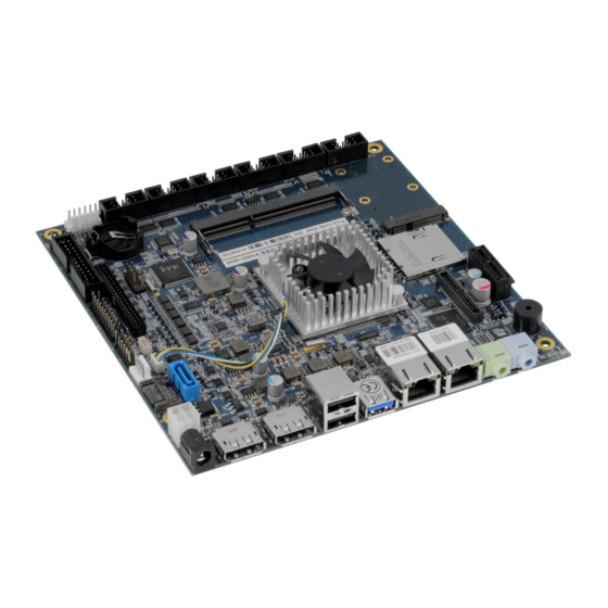
Page 16: Connector Locations
KTD-N0903-A Page 14 Connector Locations Connector Locations mITX-E38 – Frontside and Rear IO XDP (unsupported) (on backside) Clear CMOS SIM socket (on backside) COM2, COM1, COM3, COM4, COM6, COM5 Kbd/Mse USB4 USB5 FRONTPNL SODIMM FEATURE USB6 mPCIe Always On mSATA &... -
Page 17: Connector Definitions
KTD-N0903-A Page 15 Connector Definitions Connector Definitions The following sections provide pin definitions and detailed description of all on-board connectors. The connector definitions follow the following notation: Column Description name Shows the pin-numbers in the connector. The graphical layout of the connector definition tables is made similar to the physical connectors. -
Page 18: Rear Io Connectors
KTD-N0903-A Page 16 Rear IO Connectors Rear IO Connectors DC Power Jack Connector (Ext12V – J35) Either the DC Power Jack Connector (Ext12V) or the “Int12V.” connector must be used to supply the board with +12V +/-5%. The Ext12V power connector has Vin to the center pin and mates with Ø 6.3 mm DC Power jack with Ø 2.0 mm pin hole. -
Page 19: Dp Connectors (Dp1 - J24, Dp2 - J22)
KTD-N0903-A Page 17 Rear IO Connectors DP Connectors (DP1 – J24, DP2 – J22) The DP (DisplayPort) connectors are based on standard DP type Foxconn 3VD51203-H7JJ-7H or similar. Signal Description Type Note Lane 0 (p) LVDS Lane 0 (n) LVDS Lane 1 (p) LVDS Lane 1 (n) -
Page 20: Usb Connectors (Io Area)
KTD-N0903-A Page 18 Rear IO Connectors USB Connectors (IO Area) The mITX-E38 board contains support for one external USB3.0/2.0 port (USB0) and two external USB2.0 ports (USB1 and USB2). (Three internal USB2.0 ports are available via internal pin connectors and one USB2.0 port is available via mPCIe slot) USB 2.0 ports allowing data transfers up to 480Mb/s. -
Page 21: Usb Connector 1/2 (Usb1 / Usb2 - J6)
KTD-N0903-A Page 19 Rear IO Connectors USB Connector 1/2 (USB1 / USB2 – J6) USB Ports 1 and 2 supports up to USB2.0. Note Type Signal Signal Type Note 1 2 3 4 DSIO-3.3 USB1- USB1+ DSIO-3.3 1 2 3 4 DSIO-3.3 USB2- USB2+ DSIO-3.3 Signal... -
Page 22: Ethernet Connectors (Lan1 - J4 And Lan2 - J5)
KTD-N0903-A Page 20 Rear IO Connectors Ethernet Connectors (LAN1 – J4 and LAN2 – J5) Two channels of 10/100/1000Mb Ethernet based on Intel® Pearsonville i211AT PCI Express controllers are available. In order to achieve the specified performance of the Ethernet port, Category 5 twisted pair cables must be used with 10/100MB and Category 5E, 6 or 6E with 1Gb LAN networks. -
Page 23: Audio Jack Connectors (Speakers - J2, Line-In -J23)
KTD-N0903-A Page 21 Rear IO Connectors Audio Jack Connectors (Speakers – J2, Line-In –J23) The on-board Audio circuit, based on VT1708S having UAA (Universal Audio Architecture) and featuring five 24-bit stereo DACs and three 20-bit stereo ADCs, implements up to 8 Channel High Definition Audio via two audiojack connectors located in the Rear IO area, the internal Feature pin-row connector, internal MIC1 pin-row connector, internal Headphone pin-row connector and via SPDIF. -
Page 24: Internal Connectors
KTD-N0903-A Page 22 Internal Connectors Internal Connectors DC Power Internal Connector (Int12V – J7) The mITX-E38 has an internal power input connector for supplying voltage in the range from +11.4V to +12.6V. The power connector is a 4 pin 12V ATX connector type Lotes ABA-POW-003-K02 or similar. Header Signal Description... -
Page 25: Power Out Connector (Powerout - J32)
KTD-N0903-A Page 23 Internal Connectors Power Out Connector (PowerOut - J32) The Power Out connector can be used to power source external devices like HDD. The connector is type Molex 22-23-2041 or similar. Header Signal Description Type Power +5V Ground Ground Power +12V Warning: Hot Plugging power supply is not supported. -
Page 26: Internal Audio Connectors
KTD-N0903-A Page 24 Internal Connectors Internal Audio Connectors The on-board Audio circuit implements 7.1+2 Channel High Definition Audio with UAA (Universal Audio Architecture), featuring five 24-bit stereo DACs and three 20-bit stereo ADCs. The following Audio connectors are available as Internal connectors. Headphone Connector (Headphone –... -
Page 27: Fan For Soc And System (Fan Soc - J29, Fan Sys - J28)
KTD-N0903-A Page 25 Internal Connectors Fan for SOC and System (Fan SOC – J29, Fan Sys – J28) The Fan SOC is used for the connection of the FAN included in active SOC cooler. The Fan Sys can be used to power, control and monitor fan for chassis ventilation etc. Header Signal Description... -
Page 28: Ps/2 Keyboard And Mouse Connector (Kbd/Mse) (J26)
KTD-N0903-A Page 26 Internal Connectors PS/2 Keyboard and Mouse connector (KBD/MSE) (J26) Attachment of a PS/2 keyboard/mouse can be done through the pinrow connector KBD/MSE (Flex boards only). Both interfaces utilize open-drain signalling with on-board pull-up. The PS/2 mouse and keyboard is supplied from 5V when in standby mode in order to enable keyboard or mouse activity to bring the system out from power saving states. -
Page 29: Lvds Flat Panel Connector (Lvds - J31)
KTD-N0903-A Page 27 Internal Connectors LVDS Flat Panel Connector (LVDS – J31) The LVDS connector (Flex boards only) is based on 40 pole connector type Samtec SHF-120-01-F-D-SM-K- TR or similar. Note Type Signal Signal Type Note Max. 0.5A +12V +12V PWR Max. -
Page 30: Sata (Serial Ata) Disk Interface (Sata0 - J15, Sata1 - J1)
KTD-N0903-A Page 28 Internal Connectors SATA (Serial ATA) Disk interface (SATA0 – J15, SATA1 – J1) The two SATA ports available on the mITX-E38 supports SATA Gen2 (3.0/1.5Gb/s). Notes: RAID is not supported. SATA1 shared with mSATA, so that if mSATA is installed then the SATA1 is disabled. -
Page 31: Internal Usb Connectors (Usb6 - J21)
KTD-N0903-A Page 29 Internal Connectors Internal USB Connectors (USB6 – J21) USB Port 6 is supplied on the internal 10-pin- row connector USB6. Only available at E3845. Header Signal Description Type 5V protected by separate 1A resettable fuse DSIO-3.3 USB6- Differential pair 6 - DSIO-3.3 USB6+... -
Page 32: Serial Com Ports (Com1-6, J19, J18, J37, J38, J10, J9)
KTD-N0903-A Page 30 Internal Connectors Serial COM Ports (COM1-6, J19, J18, J37, J38, J10, J9) Six RS232 serial ports are available via 10-pin-row connectors. Note Ioh/Iol Type Signal PIN Signal Type Ioh/Iol Note PWR GND 9 10 PWR - The typical definition of the signals in the COM ports is as follows: Signal Description Transmitted Data, sends data to the communications link. -
Page 33: Front Panel Connector (Frontpnl - J12)
KTD-N0903-A Page 31 Internal Connectors Front Panel Connector (FRONTPNL - J12) 7.10 Pull Ioh/ Ioh/ Pull Note Type Signal Signal Type Note PWR USB4_5V USB5_5V PWR - USB4- USB5- USB4+ USB5+ PWR GND PWR - Headphone-L PWR 5V 11 12 PWR - 25/25mA O SATA_LED#... -
Page 34: Feature Connector (Feature - J27)
KTD-N0903-A Page 32 Internal Connectors Feature Connector (Feature – J27) 7.11 Note Pull U/D Ioh/Iol Type Signal Signal Type Ioh/Iol Pull U/D Note SMBCLK /4mA 10K/ 25/25mA O SMBDAT /4mA 10K/ 25/25mA O PWR_OK EXT_BAT PWR - PWR SB3V3 SB5V PWR - GPIO0 11 12... - Page 35 KTD-N0903-A Page 33 Internal Connectors The GPIO’s are controlled via the ITE IT8516F Embedded Controller. Each GPIO has 100pF to ground, clamping Diode to 3V3 and has multiplexed functionality. Some pins can be DAC (Digital to Analogue Converter output), PWM (Pulse Width Modulated signal output), ADC (Analogue to Digital Converter input), TMRI (Timer Counter Input), WUI (Wake Up Input), RI (Ring Indicator Input) or some special function.
-
Page 36: Clear Cmos Settings" (Clear Cmos - J3)
KTD-N0903-A Page 34 Internal Connectors Clear CMOS Settings” (Clear CMOS – J3) 7.12 The Jumper has 3 positions: Pin 1-2, Pin2-3 (default position) and not mounted. pin 1 Warning Don’t leave the jumper in position 1-2, otherwise if power is disconnected, the battery will fully deplete within a few weeks. -
Page 37: Always On Connector (Always On - J36)
KTD-N0903-A Page 35 Internal Connectors Always On connector (Always On - J36) 7.13 The “Always On” can be used to implement hardware controlled Always ON by jumper. When “Always On” is selected, then the board will power up automatically when power is connected. It doesn’t matter if “Always On”... -
Page 38: Spi Connector (Spi - J16)
KTD-N0903-A Page 36 Internal Connectors SPI Connector (SPI – J16) 7.14 The mITX-E38 provides one synchronous full duplex SPI (Serial Peripheral Interface) Bus in a 10 pin header connector. The connector is type Pinrex 512-90-10GBE5 or similar. Two things should be considered: An onboard SPI flash coexists on the same interface lines. -
Page 39: Lpc Connector (Lpc - J30)
KTD-N0903-A Page 37 Internal Connectors LPC Connector (LPC - J30) 7.15 The LPC connector (Flex board only) is in general unsupported. Only under special circumstances may the LPC interface be of interest. Pull Pull Note Ioh/Iol Type Signal Signal Type Ioh/Iol Note LPC CLK PWR LPC FRAME#... -
Page 40: Xdp Debug Port (Xdp - J40)
KTD-N0903-A Page 38 Internal Connectors XDP Debug Port (XDP – J40) 7.16 The XDP-CPU (Intel Debug Port for CPU) connector is not mounted and not supported. XDP connector layout (pads) is located on the backside of PCB and is prepared for the Molex 52435-2671 (or 52435-2672). Signal Description Type Pull Up/Down Note... -
Page 41: Slot Connectors
KTD-N0903-A Page 39 Slot Connectors Slot Connectors The mITX-E38 has support for PCIex1, SD Card, mPCIe or mSATA inclusive USB2.0 and SIM support PCI-Express x1 Connector (PCIex1 – J8) The PCIex1 can be used for external PCI Express cards inclusive graphics card. Maximum theoretical bandwidth is 4 Gbps effectively for each direction, 8 Gbps in total. -
Page 42: Mpcie/Msata Connector (Mpcie Or Msata & Usb - J13)
KTD-N0903-A Page 40 Slot Connectors mPCIe/mSATA connector (mPCIe or mSATA & USB – J13) The mPCIe/mSATA connector supports mSATA or PCIe and USB 2.0 and SIM socket cards. The mSATA port is shared with SATA1. Note Type Signal Signal Type Note WAKE# +3V3... -
Page 43: Onboard - & Mating Connector Types
Note: In above table, more than one connector can be listed for each type of on-board connector, if they all have same fit, form and function and are approved by Kontron as an alternative. Please notice that standard connectors like DP, PCIe, mPCIe, Audio Jack, Ethernet and USB are not included in the list.
Need help?
Do you have a question about the mITX-E3826 and is the answer not in the manual?
Questions and answers