Table of Contents
Advertisement
Quick Links
Advertisement
Table of Contents

Related Manuals for Kontron mITX-KBL-S-C236


Summary of Contents for Kontron mITX-KBL-S-C236
- Page 1 USER GUIDE mITX-KBL-S-C236 Doc. Rev. 1.4 Doc-ID: 1061-6790...
- Page 2 Kontron with respect to technical processes described in the manual or any product characteristics set out in the manual. Kontron assumes no responsibility or liability for the use of the described product(s), conveys no license or title under any patent, copyright or mask work rights to these products and makes no representations or warranties that these products are free from patent, copyright or mask work right infringement unless otherwise specified.
- Page 3 If you have any difficulties using this user guide, discover an error, or just want to provide some feedback, contact Kontron support. Detail any errors you find. We will correct the errors or problems as soon as possible and post the revised user guide on our website.
- Page 4 Doc. Rev. 1.4 www.kontron.com // 4...
- Page 5 Kontron sells products worldwide and declares regional General Terms & Conditions of Sale, and Purchase Order Terms & Conditions. Visit http://www.kontron.com/terms-and-conditions. For contact information, refer to the corporate offices contact information on the last page of this user guide or visit our website CONTACT US.
-
Page 6: Symbols
Doc. Rev. 1.4 Symbols The following symbols may be used in this manual DANGER indicates a hazardous situation which, if not avoided, will result in death or serious injury. WARNING indicates a hazardous situation which, if not avoided, could result in death or serious injury. -
Page 7: Table Of Contents
6.6. Fan Connectors (internal)..................................29 6.7. Front Panel 1 (internal) ..................................30 6.8. COM1/COM2 external ..................................... 31 6.9. Kontron Feature Connector (GPIO Internal) ........................... 32 6.10. CMOS1 Jumper ......................................33 6.11. Always ON Jumper ....................................33 6.12. LCD_PWR1 Internal....................................34 6.13. -
Page 8: List Of Tables
Doc. Rev. 1.4 Technical Support ..................................... 80 9.1. Warranty ........................................80 9.2. Returning Defective Merchandise ..............................80 List of Acronyms ......................................82 About Kontron ........................................83 List of Tables Table 1: Component Main Data ..................................16 Table 2: Environmental Conditions ................................18 Table 3: Certification and Compliance Information .......................... - Page 9 Doc. Rev. 1.4 Figure 12: COM1/2 External Connector (2 mm raster) ......................... 31 Figure 13: GPIO Internal Connector ................................32 Figure 14: CMOS1 Jumper ....................................33 Figure 15: Always ON Jumper ..................................33 Figure 16: LCD_PWR1 Internal Connector ..............................34 Figure 17: LVDS Connector ....................................
-
Page 10: 1/ Introduction
Doc. Rev. 1.4 1/ Introduction This manual describes the Mini ITX 8th generation S-C236 board. This board will also be denoted mITX-KBL-S-C236 within this Users Guide. The use of this Users Guide implies a basic knowledge of PC hard- and software. This manual is focussed on describing the mITX-KBL-S-C236 board’s special features and is not intended to be a standard PC textbook. -
Page 11: 2/ Description
Doc. Rev. 1.4 2/ Description The mainboard mITX-KBL-S-C236 is based on the 8th generation processor family. It uses the Chipset C236 PCH from Intel. This powerful hardware with efficient graphic and network capabilities offers a broad range of application areas. The processor, graphics and memory controller is built on 22 nm die. -
Page 12: 3/ Installation Procedure
• Handle the board only by the edges To get the board running follow these steps. If the board shipped from Kontron has already components like RAM and CPU cooler mounted, then relevant steps below can be skipped. Turn off the PSU (Power Supply Unit) Turn off PSU (Power Supply Unit) completely (no mains power connected to the PSU) or leave the Power Connectors unconnected while configuring the board. -
Page 13: Requirements Iec60950-1
3.3. Requirements IEC60950-1 Take care when designing chassis interface connectors in order to fulfil the IEC60950-1 standard. Users of mITX-KBL-S-C236 must evaluate the end product to ensure compliance the requirements of the IEC60950- 1 safety standard are met: The motherboard must be installed in a suitable mechanical, electrical and fire enclosure. -
Page 14: Lithium Battery Precautions
Doc. Rev. 1.4 3.4. Lithium battery precautions Danger of explosion if the lithium battery is incorrectly replaced. • Replace only with the same or equivalent type recommended by the manufacturer Dispose of used batteries according to the manufacturer’s instructions •... -
Page 15: 4/ System Specifications
Doc. Rev. 1.4 4/ System specifications 4.1. Functional Block Diagram Figure 1: Functional Block Diagram www.kontron.com // 15... -
Page 16: Component Main Data
Doc. Rev. 1.4 4.2. Component Main Data The table below summarizes the features of the mITX-KBL-S-C236 embedded motherboard. Table 1: Component Main Data Motherboard mITX-KBL-S-C236 Form factor Mini ITX (170.18 mm by 170.18 mm) Processor Onboard CPU variants Intel® 8th generation S Processor line, LGA1151 CPU Socket (37.5 mm x 37.5 mm) Range from 65 to 80 W TDP, Core™... - Page 17 Doc. Rev. 1.4 CMOS Clear 1x (1x 3 ) 2 mm pin-header Front Panel 1x 24 pin connector Power COM pin 9 2x ( 2x 3 ) 2.0 mm pin-header; PS/2 1x(2x3) 2.0 mm pin-header (for installing Windows) Display Intel®Gen 9 LP (generation 9 Low Power) graphics core with three pipes and 72 Execution...
-
Page 18: Table 2: Environmental Conditions
-20°C~70°C (-4°F~176°F); lower limit of storage temperature is defined by specification restriction of on-board CR2032 battery. Board with battery has been verified for storage temperature down to -40 C by Kontron. Up to 95 % relative humidity (temperature 25°C to 30°C) Radiated Emissions All Peripheral interfaces intended for connection to external equipment are EMI protected. -
Page 19: 5/ Jumpers And Connectors
Doc. Rev. 1.4 5/ Jumpers and Connectors 5.1. Hardware Configuration Setting This chapter gives the definitions and shows the positions of jumpers, headers and connectors. All of the configuration jumpers on the board are in the proper position. The default settings shipped from factory are marked with an asterisk (*). -
Page 20: Mainboard Placement And Rear I/O Locations
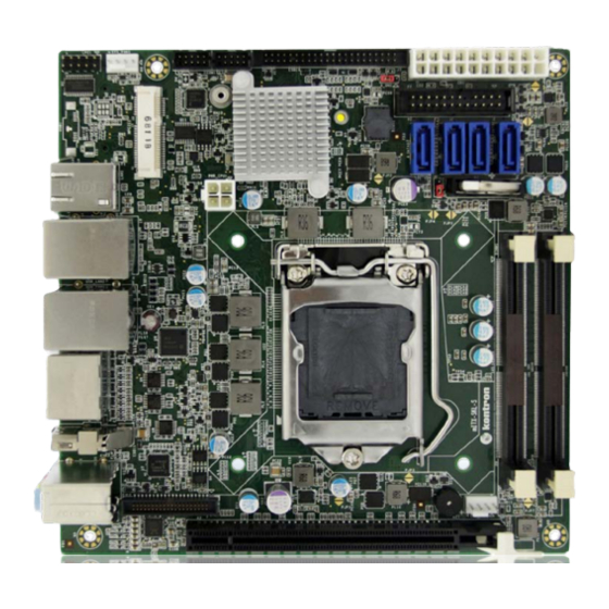
Doc. Rev. 1.4 5.2. Mainboard Placement and Rear I/O locations Figure 2: Front Side and Interfaces ATX-4-pin Power connector ATX 12 V power interface LPC1 Bus SATA connector Sys-Fan Battery holder Com1 Memory connector Com2 CPU connector PCH chip controller... -
Page 21: Figure 3: Rear View With Interfaces
Doc. Rev. 1.4 Figure 3: Rear View with Interfaces 4xUSB/3xEthernet 2x Display Port 1x DisplayPort (optional) Audio jacks www.kontron.com // 21... -
Page 22: Rear Side
Doc. Rev. 1.4 5.3. Rear Side Figure 4: Bottom Side M.2 Interface Mounting hole for M.2-card www.kontron.com // 22... -
Page 23: 6/ Pin Definitions
Doc. Rev. 1.4 6/ Pin Definitions The following sections provide pin definitions and detailed description of all on-board connectors. The connector definitions follow the following notation: Table 4: Connector Definitions Column Name Description Shows the pin-numbers in the connector. The graphical layout of the connector definition tables is made similar to the physical connectors. -
Page 24: Processor Support
Intel® Core i7, -i5, -i3 Quad Core processor Intel® Xeon processor Kontron has defined the board versions as listed in the following table, so far all based on Embedded CPUs. Table 5: Processor Support Name Speed Turbo Embed. -
Page 25: Ethernet Connectors (I/O Area)
1060-2764 6.3. Ethernet Connectors (I/O area) The mITX-KBL-S-C236 supports three channels of 10/100/1000 Mbit/s Ethernet (LAN1 to LAN3). In order to achieve the specified performance of the Ethernet port, Category 5 twisted pair cables must be used with 10/100 MByte/s and Category 5E, 6 or 6E with 1 Gbit/s LAN networks. -
Page 26: Usb Connectors (I/O Area)
Doc. Rev. 1.4 Signal Description In MDI crossover mode, this pair acts as the BI_DD+/- pair. MDI[3]+ / MDI[3]- In MDI mode, this is the fourth pair in 1000Base-T, i.e. the BI_DD+/- pair. In MDI crossover mode, this pair acts as the BI_DC+/- pair. -
Page 27: Figure 7: Usb 2.0 High Speed Cable
Doc. Rev. 1.4 Figure 7: USB 2.0 High Speed Cable Polyvinyl Chloride (PVC) Jacket On-Twisted Power Pair: Red: V Black: Power Ground Twisted Signaling Pair: White: D- Green: D+ Inner Shield Aluminum Metallized Polyester Outer Shield ≥ 65% Interwoven... -
Page 28: Audio Jack Connectors (I/O Area)
Doc. Rev. 1.4 6.5. Audio Jack Connectors (I/O area) Figure 9: Audio Jack Ring Sleeve Mating Audio Jack (example) Table 11: Pin Assignment (Line Out, green) Pin Designation Signal Type Note Front_OUT_L For headphone, max 1.6 V Ring Front_OUT_R For headphone, max 1.6 V... -
Page 29: Fan Connectors (Internal)
Doc. Rev. 1.4 6.6. Fan Connectors (internal) The FANSYS (SYS_FAN) can be used to power, control and monitor a fan for chassis ventilation etc. The FANCPU (CPU_FAN) is used for the connection of the FAN for the CPU. The 4-pin header is recommended to be used for driving 4-wire type Fan in order to implement FAN speed control. -
Page 30: Front Panel 1 (Internal)
Doc. Rev. 1.4 6.7. Front Panel 1 (internal) Figure 11: FP1 Connector Table 17: FP1 Connector Signal Signal USB6/7_5V USB6/7_5V USB6- USB7- USB6+ USB7+ LINE2-L SATA_LED SUS_LED PWRBTN_IN# RSTIN# SBV3V3 LINE-2R AGND AGND MIC2-L MIC2-R www.kontron.com // 30... -
Page 31: Com1/Com2 External
Doc. Rev. 1.4 6.8. COM1/COM2 external Figure 12: COM1/2 External Connector (2 mm raster) Table 18: COM1/2 External Connection Description Description NDCD NDSR NSIN NRTS NSOUT NCTS NDTR Table 19: Signal Description Signal Description NDCD Data Carrier Detect NDSR... -
Page 32: Kontron Feature Connector (Gpio Internal)
Doc. Rev. 1.4 6.9. Kontron Feature Connector (GPIO Internal) Figure 13: GPIO Internal Connector Table 20: Pinout GPIO Description Description CASE_OPEN# SMBC SMBD PWR_OK EXT_BAT FAN3OUT FAN3IN SB3V3 SB5V GPIO0 GPIO1 GPIO2 GPIO3 GPIO4 GPIO5 GPIO6 GPIO7 GPIO8 GPIO9... -
Page 33: Cmos1 Jumper
Doc. Rev. 1.4 6.10. CMOS1 Jumper Figure 14: CMOS1 Jumper Table 21: CMOS1 Internal Connection Description 3V_BATT RTCRST# Function: Pin1-2: Default Position Pin2-3: Clear CMOS 6.11. Always ON Jumper Figure 15: Always ON Jumper Table 22: Always ON Jumper... -
Page 34: Lcd_Pwr1 Internal
Doc. Rev. 1.4 6.12. LCD_PWR1 Internal Figure 16: LCD_PWR1 Internal Connector Table 23: LCD_PWR1 Internal Connection Description LCD_VOLTAGE 3.3V 6.13. LVDS (internal) Figure 17: LVDS Connector Table 24: LVDS Pin Assignment Description Description 12 V 12 V 12 V... -
Page 35: Sata (Serial Ata) Disk Interfaces (Internal)
Doc. Rev. 1.4 Description Description LVDS B3- LVDS B3+ 6.14. SATA (Serial ATA) Disk Interfaces (internal) Figure 18: SATA Connector Table 25: Pin Assignment Signal Type SATA* TX+ SATA* TX- SATA* RX- SATA* RX+ Table 26: Signal Description Signal... -
Page 36: 7/ Features And Power Supply
Doc. Rev. 1.4 7/ Features and Power Supply 7.1. Onboard Power Supply The KBL-S/mITX implements an on-board Intel IMVP8 regulator for the processor core and graphics core power supply. The main feature of Intel IMVP8 regulator is that it is serial Voltage Identification Definition (VID) based. Both the processor core and graphics core Voltage Regulator (VRs) are integrated into a single package. -
Page 37: Power Management
Doc. Rev. 1.4 7.3. Power Management Processor supports ACPI 4.0a C0, C1, C1E, C3, C6, C7, C8, C9, C10 states. All power management handshakes are made on the DMI interface. None of the ‘Power State’ status signals can be observed on the board directly. -
Page 38: 8/ Bios Setup Structure
Doc. Rev. 1.4 8/ BIOS Setup structure The Setup utility features for menus listed in the selection bar at the top of the screen: Main Advanced Chipset Security Boot Save & Exit The Setup menus are selected via the left and right arrow keys. The currently active menu and the currently active uEFI BIOS Setup item are highlighted in white. - Page 39 Doc. Rev. 1.4 Sub-Screen Function Description Low Power SO Idle Enable/Disable Low Power SO Idle Lpit Recidency Counter Select Recidency Counter PCI Delay Optimization Enable/Disable PCI Delay Optimization ZpODD Enable/Disable ZpODD C6DRAM Enable/Disable C6DRAM SW Guard Extensions (SGX) Enable/Disable Software Guard...
- Page 40 Doc. Rev. 1.4 Sub-Screen Function Description Flash Wear Out Protection Enable/Disable Flash Wear Out Protection Current Debug Interface Status Display Current Debug Interface Status Debug Interface Enable/Disable Debug Interface Support Debug Interface Lock Enable/Disable Debug Interface Lock Processor trace memory allocation...
- Page 41 Doc. Rev. 1.4 Sub-Screen Function Description Configurable TDP Enable/Disable Configurable TDP Lock Lock CTDP BIOS Control Enable/Disable CTDP Control via runtime ACPI BIOS methods ConfigTDP Levels ConfigTDP Turbo Activation Ratio, Power Limit 1, Power Limit 2 Custom Settings Setting for Power Limit 1, Power Limit 2,...
- Page 42 Doc. Rev. 1.4 Sub-Screen Function Description Display PS Current Threshold3 Current Threshol Enable/Disable PS3 Enable Enable/Disable PS4 Enable IMON Display IMON Slope Slope IMON Display IMON Offset Offset IMON Set the Offset value as positive or Prefix negative Display VR Current Limit...
- Page 43 Doc. Rev. 1.4 Sub-Screen Function Description Threshol Enable/Disable PS3 Enable Enable/Disable PS4 Enable IMON Display IMON Slope Slope IMON Display IMON Offset Offset IMON Set the Offset value as positive or Prefix negative Display VR Current Limit Current Limit...
- Page 44 Doc. Rev. 1.4 Sub-Screen Function Description Enable/Disable PS3 Enable Enable/Disable PS4 Enable IMON Display IMON Slope Slope IMON Display IMON Offset Offset IMON Set the Offset value as positive or Prefix negative Display VR Current Limit Current Limit Display VR Voltage Limit...
- Page 45 Doc. Rev. 1.4 Sub-Screen Function Description IO MWAIT Redirection When set, will map IO_read instructions sent to IO registers PMG_IO_BASE_ADDRBASE+off set to MWAIT(offset) Package C State Limit Maximum Package C State Limit Setting C3 Latency Control (MSR 0X60A) Setting of Time Unit (Unit of...
- Page 46 Doc. Rev. 1.4 Sub-Screen Function Description Features State Display Features State AMT BIOS Features Display AMT BIOS Features AMT Configuration ASF support Enable/Disable Alert Standard Format Support USB Provisioning of AMT Enable/Disable of AMT USB Provisioning CIRA Active Trigger CIRA boot...
- Page 47 Doc. Rev. 1.4 Sub-Screen Function Description ME Unconfig on RTC Clear Display ME Unconfig on RTC Clear Comms Hub Support Enable/Disable support for Comms Hub JHI Support Enable/Disable Intel® DAL Host Interface Service (JHI) Core Bios Done Message Enable/Disable Core Bios Done message...
- Page 48 Doc. Rev. 1.4 Sub-Screen Function Description SensorHub Delay after applying power to SensorHub device I2C1 Controller Delay in _PSO I2C1 Controller TouchPad Delay after applying power to TouchPad device TouchPanel Delay in PR _ON after applying power to TouchPanel device...
- Page 49 Doc. Rev. 1.4 Sub-Screen Function Description Hibernate ACPI Sleep State Select the highest ACPI sleep state the system will enter when the SUSPEND button is pressed Lock Legacy Resources Enable/Disable Lock Legacy Resources S3 Video Repost Enable/Disable S3 Video Repost...
- Page 50 Doc. Rev. 1.4 Sub-Screen Function Description Putty KeyPad Select function key and keypad on Putty Redirection After BIOS The settings specify if bootLoader is POST selected then Legacy console redirection is disable before booting to Legacy OS COM1(Pci Bus0, Dev0, Func0)
- Page 51 Doc. Rev. 1.4 Sub-Screen Function Description LVDS LVDS Flat Panel Display Support Enable/Disable LVDS Flat Panel Display Configuration Support Panel Type Select the type or Manufacturer’s name of the display panel Resolution Select the screen resolution of the display panel...
-
Page 52: Chipset Setup Menu
Doc. Rev. 1.4 Sub-Screen Function Description specified speed Watchdog Function 0 = Disable. Enter the service interval in seconds before the system will reset ITE8528 Firmware Update This option is enable Auto Update when version is not match, force update or... - Page 53 Doc. Rev. 1.4 Sub-Screen Function Description floor values Dram Display Dram Power Meter Setting Power Meter Setting Memory Lock Enabled: lock several PCU Thermal Thermal registers related to DDR Reportin Manage power/thermal ment management Register Extern Enabled: The value from...
- Page 54 Doc. Rev. 1.4 Sub-Screen Function Description Warm Range [255;0]=[31.875;0] in Thresho W for OLTM, [127.5;0] in C ld Ch1 for CLTM Dimm1 Range [255;0]=[31.875;0] in Thresho W for OLTM, [127.5;0] in C for CLTM ld Ch1 Dimm0 Range [255;0]=[31.875;0] in Thresho W for OLTM, [127.5;0] in C...
- Page 55 Doc. Rev. 1.4 Sub-Screen Function Description 1 enable Disable(Disable= Def) RAPL PL Range[0;2^14- 1 Power 1]=[2047.875;0] in W, (0= Def) RAPL PL Power PL 1 time windowX value, Window (1/1024)*(1+(x/4))*(2^y)(0= Def) RAPL PL Power PL 1 time windowY value,...
- Page 56 Doc. Rev. 1.4 Sub-Screen Function Description Time Centering 2D Write Timing Centering 1D Enable/Disable Write Timing Centering 1D Write Voltage Centering 1D Enable/Disable Write Voltage Centering 1D Read Timing Centering 1D Enable/Disable Read Timing Centering 1D Dimm ODT Training*...
- Page 57 Doc. Rev. 1.4 Sub-Screen Function Description DIMM SPD Alias Test Test to determine if the SPD has been corrupted to cause memory aliasing Receive Enable Centering 1D Enable/Disable Receive Enable Centering 1D Retrain Margin Check Enable/Disable Retrain Margin Check...
- Page 58 Doc. Rev. 1.4 Sub-Screen Function Description Probeless Trace HD Port, GDXC IOT/MOT od Disable Enable/Disable IED (Intel Enhanced Debug) Intel Enhanced Debug requires 4MB SMM memory Ch Hash Support Enable/Disable Channel Hash Support Ch Hash Mask Set the BIT(s) to be included...
- Page 59 Doc. Rev. 1.4 Sub-Screen Function Description AUTO: 64 for ULX/ULT, 128 for DT/Halo Mrc Fast Boot Enable/Disable fast path thru the MRC Lpddr Mem WL Set Only applicable to LPDDR, Memory Write Latency Set selection (A is default, B will...
- Page 60 Doc. Rev. 1.4 Sub-Screen Function Description PAVP Enable Enable/Disable PAVP Cdynmax Clamping Enable Enable/Disable Cdynmax Clamping Cd Clock Frequency Select the highest Cd Clock Frequency supported by the platform IUER Button Enable Enable/Disable IUER Button Functionality DMI/OPI DMI Max Link Speed...
- Page 61 Doc. Rev. 1.4 Sub-Screen Function Description control on DMI DMI IOT Enable/Disable DMI IOT PEG Port PEG 0:1:0 Enable Root Port Enable/Disable the Root Configuration Port Max Link Speed Configure PEG 0:1:0 Max Speed PEGO Slot Power Limit Value...
- Page 62 Doc. Rev. 1.4 Sub-Screen Function Description value for each Lane Lane 1 Value for Lane 1 Lane 2 Value for Lane 2 Lane 3 Value for Lane 3 Lane 4 Value for Lane 4 Lane 5 Value for Lane 5...
- Page 63 Doc. Rev. 1.4 Sub-Screen Function Description Lane 5 Value for Lane 5 Lane 6 Value for Lane 6 Lane 7 Value for Lane 7 Lane 8 Value for Lane 8 Lane 9 Value for Lane 9 Lane 10 Value for Lane 10...
- Page 64 Doc. Rev. 1.4 Sub-Screen Function Description test mode Jitter Dwell Time PEG Gen3 Preset Search dwell time [0..65535] in [usec] Jitter Error Target The margin search error target value [1..65535] VOC Dwell Time The VOC margin search dwell time [0..65535] in...
- Page 65 Doc. Rev. 1.4 Sub-Screen Function Description Peer Memory Write Enable Peer Memory Write Enable/Disable Compliance Test Mode Enable when using Compliance Load Board PCIe-USB Glitch W/A PCIe-USB Glitch W/A for bad USB device(s) connected behind PCIE/PEG Port PCIe Function swap...
- Page 66 Doc. Rev. 1.4 Sub-Screen Function Description PCIE15 Cm Display PCIE15 Cm PCIE15 Cp Display PCIE15 Cp PCIE16 Cm Display PCIE16 Cm PCIE16 Cp Display PCIE16 Cp PCIE17 Cm Display PCIE17 Cm PCIE17 Cp Display PCIE17 Cp PCIE18 Cm Display PCIE18 Cm...
- Page 67 Doc. Rev. 1.4 Sub-Screen Function Description Enable/Disable PCI Express Completion Timer T0 Enable/Disable SEFE Root PCI Express System Error on Fatal Error Enable/Disable SENFE Root PCI Express System Error on Non-Fatal Error Enable/Disable SECE Root PCI Express System Error on Correctable Error...
- Page 68 Doc. Rev. 1.4 Sub-Screen Function Description Override default platform mapping Extra Detect Non- Detect Non-Compliance PCI options Express Device Compliance Device Prefetchable Prefetchable Memory Memory Range for this Root Bridge Reserved Reserved Memory Memory Alignment (0-31 bits) Alignment Prefetchable...
- Page 69 Doc. Rev. 1.4 Sub-Screen Function Description DITO Configuration Enable/Disable DITO Configuration DITO Value Display DITO Value DM Value Display DM Value SATA1 mSATA: Unknown Software Preserve Software Preserve Port 1 Enable/Disable SATA Port Hot Plug Designates this port as Hot...
- Page 70 Doc. Rev. 1.4 Sub-Screen Function Description DITO Value Display DITO Value DM Value Display DM Value SATA3 J12: Unknown Software Preserve Software Preserve Port 3 Enable/Disable SATA Port Hot Plug Designates this port as Hot Pluggable Configured as eSATA...
- Page 71 Doc. Rev. 1.4 Sub-Screen Function Description SATA7 J13: Unknown Software Preserve Software Preserve Port 7 Enable/Disable SATA Port Designates this port as Hot Pluggable Configured as eSATA Hot Plug Supported Spin Up Device Enable/Disable Spin Up Device SATA Device Type...
- Page 72 Doc. Rev. 1.4 Sub-Screen Function Description iDisplay Audio Disconnect Disconnects SDI2 signal to hide/disable iDisplay Audio Codec PME Enable Enables PME wake of HD Audio controller during POST HD Audio I/O Buffer Select the ownership of the Advanced Control:...
- Page 73 Doc. Rev. 1.4 Sub-Screen Function Description Detection Feature Audio DSP Enables/Disables 3rd Party Pre/Post- Processing Module Support Processing (identified by GUID) Module Support: Waves Post- process Enables/Disables 3rd Party Processing Module Support (identified by GUID) IntelSST Speech Enables/Disables 3rd Party...
- Page 74 Doc. Rev. 1.4 Sub-Screen Function Description Icepower IP Enables/Disables 3rd Party MFX sub Processing Module Support module (identified by GUID) Icepower IP EFX Enables/Disables 3rd Party sub module Processing Module Support (identified by GUID) Icepower IP SFX Enables/Disables 3rd Party...
- Page 75 Doc. Rev. 1.4 Sub-Screen Function Description Settings Connected Device Indicate what type of device is connected to this serial IO controller Serial IO ChipSelect Polarity Sets initial polarity for SPI0 ChipSelect signal Settings Serial IO Bluetooth Device Enables/Disables the...
- Page 76 Doc. Rev. 1.4 Sub-Screen Function Description the DCI which allows debug over the USB3 interface DCI Auto Detect Enable When set to Auto Detect, it detect DCI being connected during BIOS post time and enables DCI Debug Port Selection...
-
Page 77: Security Setup Menu
Doc. Rev. 1.4 Sub-Screen Function Description PCH Cross Throttling Enable/Disable PCH Cross Throttling feature Disable energy reporting Enable/Disable energy reporting feature Enable TC0 Timer Enable/Disable TC0 timer Pcie Pll SSC Pcie Pll SSC percentage Unlock PCH P2SB Unlock PCH P2SB SBI and... - Page 78 Doc. Rev. 1.4 Function Description Intel® BIOS Guard Intel BIOS Guard Support Enable or Disable Intel BIOS Guard Technology Support Intel TXT Display Intel TXT Information (Chipset, BiosScm, Chipset Txt, Cpu Txt, Error Code, Class Code, Information Major Code and Minor Code)
-
Page 79: Boot Setup Menu
Doc. Rev. 1.4 8.5. Boot Setup Menu The Boot Setup menu lists the for boot device priority order, which is dynamically generated. Table 32: Boot Priority Order Function Description Boot Configuration Number of seconds to wait for setup activation key... -
Page 80: 9/ Technical Support
Visit the RMA Information website: http://www.kontron.com/support-and-services/support/rma-information Download the RMA Request sheet for Kontron Europe GmbH and fill out the form. Take care to include a short detailed description of the observed problem or failure and to include the product identification Information (Name of product, Product number and Serial number). - Page 81 Doc. Rev. 1.4 The goods for repair must be packed properly for shipping, considering shock and ESD protection. Goods returned to Kontron Europe GmbH in non-proper packaging will be considered as customer caused faults and cannot be accepted as warranty repairs.
-
Page 82: List Of Acronyms
Doc. Rev. 1.4 List of Acronyms Error Checking and Correction Real Time Clock Field Replaceable Unit Trusted Platform Module Graphics Processing Unit UEFI Unified Extensible Firmware Interface Hard Disk mITX Mini ITX PCIe PCI-Express PECI Platform Environment Control Interface www.kontron.com... -
Page 83: About Kontron
About Kontron Kontron is a global leader in Embedded Computing Technology (ECT). As a part of technology group S&T, Kontron offers a combined portfolio of secure hardware, middleware and services for Internet of Things (IoT) and Industry 4.0 applications. With its standard products and tailor-made solutions based on highly reliable state-of-the-art embedded technologies, Kontron provides secure and innovative applications for a variety of industries.
Need help?
Do you have a question about the mITX-KBL-S-C236 and is the answer not in the manual?
Questions and answers