
Related Manuals for MKS 579A


Summary of Contents for MKS 579A
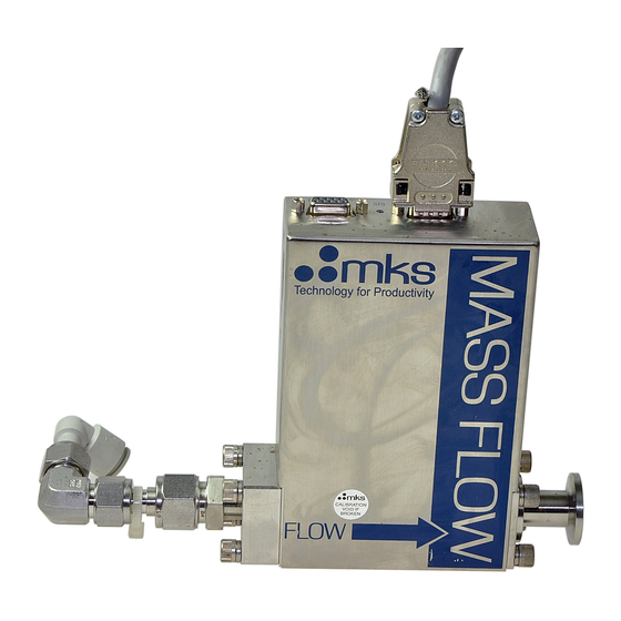
- Page 1 Y-1951579A Digital Mass Flow Controller Type 1579A/B Digital Mass Flow Meter 579A/B - Instruction Manual - FLOW MKS Instruments Edition 2010-07 Deutschland GmbH...
- Page 2 MKS Instruments. Printed in the Federal Republic of Germany Mass-Flo ® is a registered trademark of MKS Instruments, Inc., Andover, MA Swagelok ® , VCR ® , and VCO ® are registered trademarks of Swagelok Marketing Company, Solon, OH Cajon ®...
-
Page 3: Table Of Contents
Chapter 3: Connectors and Control Elements .................21 Analog Units ..........................21 Potentiometer ZERO......................22 AUTOZERO ........................22 RESET Switch ........................22 Connector SETUP ......................22 Electrical Connector ........................23 1579A/B / 579A/B, Analog Unit..................23 Profibus Units..........................24 Potentiometer ZERO......................25 AUTOZERO ........................25 RESET Switch ........................25 Address and Mode switch A/B..................25 Status LED STS........................25... - Page 4 Table of Contents 1579A/579A Electrical Connectors ....................... 26 1579A/B / 579A/B, Profibus Units, Connector ANALOG ..........26 1579A/B / 579A/B, Profibus Units, Connector PROFIBUS..........27 Chapter 4: Operation ........................29 General Requirements ......................29 Environmental ........................29 Location and Orientation....................30 Leak Integrity........................
- Page 5 1579A/579A Table of Contents Start Up the Mass Flow Controller ....................42 Zeroing the Flow Controller.......................43 Status LED STS ........................44 Address and Mode Switch A/B ....................44 Switch Assignment......................44 Mode B..........................44 Setting an Address......................45 Mode A..........................45 Zero Modes........................45 PROFIBUS Protocol........................46 Data Interface..........................46 Send Data .........................47...
- Page 6 To Order a Mass Flow Meter ................... 78 Appendix C: Gas Correction Factors ....................79 Appendix D: Binary Code ........................ 83 MKS Worldwide Calibration & Service Centers ................85 There is a Health and Safety Form on the last page of this instruction manual.
- Page 7 Table of Contents List of Figures Figure 1: Model Code Label ......................19 Figure 2: 1579A/B / 579A/B Side View ....................21 Figure 3: 1579A/B / 579A/B Connector Side..................21 Figure 4: 1579A/B / 579A/B Gas Inlet Side..................22 Figure 5: 15-pol. connector ......................23 Figure 6: 1579A/B / 579A/B Side View ...................24...
- Page 8 Table of Contents 1579A/579A This page intentionally left blank viii...
-
Page 9: Safety Information
1579A/579A Safety Information Safety Information Symbols Used in This Instruction Manual Definitions of WARNING, CAUTION, and NOTE messages used throughout the manual. The WARNING sign denotes a hazard. It calls attention to a Warning! procedure, practice, condition, or the like, which, if not correctly performed or adhered to, could result in injury to personnel. -
Page 10: Safety Procedures And Precautions
DO NOT SUBSTITUTE PARTS OR MODIFY INSTRUMENT Do not install substitute parts or perform any unauthorized modification to the instrument. Return the instrument to an MKS Calibration and Service Center for service and repair to ensure that all safety features are maintained. - Page 11 1579A/579A Safety Information OPERATE AT SAFE INLET PRESSURES Never operate at pressures higher than the rated maximum pressure (refer to the product specifications for the maximum allowable pressure). INSTALL A SUITABLE BURST DISC When operating from a pressurized gas source, install a suitable burst disc in the vacuum system to prevent system explosion should the system pressure rise.
- Page 12 Safety Information 1579A/579A This page intentionally left blank...
-
Page 13: Chapter 1: General Information
The digital mass flow controllers of the 1579A/B series accurately measure and control the mass flow rate of gases. The type 579A/B of this series, however, is a mass flow meter for mass flow measurement only, therefore without a control valve. -
Page 14: Power Supply And Readout Units
1579A/579A Power Supply and Readout Units The analog versions of the 579A/B/1579A/B series can interface to complementary MKS equipment which are available as single channel, dual channel, four and eight channel units to display the flow signal and to provide the power and set point commands, where applicable. Almost all control units are equipped with serial interface. -
Page 15: Instruction Manual
Designations and Names The mass flow meter 579A/B will only be mentioned in particular where this is necessary, else wise the instructions for the 1579A/B also apply for the meter 579A/B. - Page 16 Chapter 1: General Information 1579A/579A This page intentionally left blank...
-
Page 17: Chapter 2: Shipment
If you find any damage, please notify your carrier and MKS immediately. If it is necessary to return the unit to MKS, obtain an ERA Number (Equipment Return Authorization Number) from the MKS Service Center before shipping. -
Page 18: Profibus Units
Chapter 2: Shipment 1579A/579A Profibus Units Mass flow controller 1579A/B or mass flow monitor 579A/B, respectively Accessory kit ZB-27 consisting of • Mating connector D-type; 9 pin female • Mating connector D-type; 9 pin male • 2 mounting screws #8-32 UNF (MKS part no. 160-3973) GSD file (3,5”... -
Page 19: Label
Gas type N2 (the range is related to this gas) Serial number 560942G20 CE mark Manufacturer MKS Instruments Deutschland GmbH SN: 560942G20 1579A01322LR1BV / Viton 200 slm / N2 MKS Instruments Deutschland GmbH Figure 1: Model Code Label Across the housing and the meter/controller body there is an extra label to avoid access to the inside by unauthorized people. - Page 20 Chapter 2: Shipment 1579A/579A This page intentionally left blank...
-
Page 21: Chapter 3: Connectors And Control Elements
Chapter 3: Connectors and Control Elements Analog Units Status LED (STS) ZERO SETUP RESET AUTOZERO FLOW Figure 2: 1579A/B / 579A/B Side View (Imprint on type 579A/B: MASS-FLOW METER ) Sub-D Stecker Status LED 15 pol. (STS) Figure 3: 1579A/B / 579A/B Connector Side... -
Page 22: Potentiometer Zero
1579A/579A ZERO SETUP RESET AUTOZERO Figure 4: 1579A/B / 579A/B Gas Inlet Side Potentiometer ZERO Use this 25 turn potentiometer to adjust the signal output to zero. Refer to Chapter 5, Zero Adjust. AUTOZERO Instead of potentiometer ZERO you can use this push button to zero the signal output. -
Page 23: Electrical Connector
Shield, Case Figure 5: 15-pol. connector For use with control units from MKS Instruments (PR 4000, 647 etc.) we recommend to use the standard cables of the manufacturer. Any appropriate 0 to +5 V signal of less than 20 Ω source impedance Note can be used to supply a set point signal to pin 8. -
Page 24: Profibus Units
Chapter 3: Connectors and Control Elements 1579A/579A Profibus Units Status LED (STS) ZERO RESET AUTOZERO FLOW Figure 6: 1579A/B / 579A/B Side View (Imprint on type 579A/B: MASS-FLOW METER ) Status LED (STS) PROFIBUS ANALOG Figure 7: 1579A/B / 579A/B Connector Side... -
Page 25: Potentiometer Zero
1579A/579A Chapter 3: Connectors and Control Elements ZERO RESET AUTOZERO Figure 8: 1579A/B / 579A/B Gas Inlet Side Potentiometer ZERO Use this 25 turn potentiometer to adjust the signal output to zero. Refer to Chapter 6, Zero Adjust. AUTOZERO Instead of potentiometer ZERO you can use this push button to zero the signal output. -
Page 26: Electrical Connectors
Chapter 3: Connectors and Control Elements 1579A/579A Electrical Connectors 1579A/B / 579A/B, Profibus Units, Connector ANALOG (9 pol. Sub-D, male) ± 15 V Supply 24 V Supply Note Valve Open / Valve Close Valve Open / Valve Close Flow Signal... -
Page 27: 1579A/B / 579A/B, Profibus Units, Connector Profibus
1579A/579A Chapter 3: Connectors and Control Elements 1579A/B / 579A/B, Profibus Units, Connector PROFIBUS (9 pol. Sub-D, female) Signal Note RXD / TXD – P Bus positive CNTR – P Control for Repeater, positive DGND Digital Ground Power Supply ( 5V ) RXD / TXP –... - Page 28 Chapter 3: Connectors and Control Elements 1579A/579A This page intentionally left blank...
-
Page 29: Chapter 4: Operation
1579A/579A Chapter 4: Operation Chapter 4: Operation General Requirements Environmental Follow the guidelines below when installing and using your mass flow controller. Maintain the normal operating temperature between 15 – 40 °C (59 and 104 °F). Observe the pressure limits •... -
Page 30: Location And Orientation
Chapter 4: Operation 1579A/579A Location and Orientation Set the controller into position where it will be connected to a gas supply. Placement of flow components in an orientation other than that in which they were calibrated (typically horizontal) may cause a small zero shift. The zero offset can be removed according to the instructions in Chapter 5, Zero Adjust if an analog unit is used or in Chapter 6, Zeroing the Flow Controller if a profibus unit is used. -
Page 31: Dimensions
Units. (All dimensions are listed in millimetres. Conversion: 1 inch = 25,4 mm) FLOW Figure 11: 1579A/B / 579A/B Dimensions (Side) (Shown: analog unit; Imprint on type 579A/B: MASS-FLOW METER) Fittings (compatible) L in mm 183,0 ± 1 8 VCR 174,5 ±... -
Page 32: Mounting Holes
Chapter 4: Operation 1579A/579A ZERO SETUP RESET AUTOZERO Figure 12: Dimensions (Inlet/Outlet side) Mounting Holes 78,5 8-32 UNC 10-24 UNC 21,85 25,4 38,1 Figure 13: Mounting Holes (Flow direction from left to right) -
Page 33: Mounting Plate
Braided shielded cables must be used. The PROFIBUS cable must be qualified. Cables and Controllers by MKS For use of the analog versions of the types 579A/B and 1579A/B with controllers, power supplies, readout units etc. by MKS standard cables are available. Flow Controller/Meter... -
Page 34: Power Supply / Readout Units Of Other Manufacturers
1579A/579A Power Supply / Readout Units of other Manufacturers Should you use power supplies / readout units of manufacturers other than MKS then make sure that these units fulfil the electrical specifications for use with the mass flow controllers/meters as described herein. -
Page 35: Chapter 5: Operation (Analog Units)
1579A/579A Chapter 5: Operation (Analog Units) Chapter 5: Operation (Analog Units) Start Up the Mass Flow Controller/Meter After you have successfully checked all mechanical and electrical connections and when you are certain that there is no gas leakage, then power can be applied to the mass flow controller or to the flow meter, respectively. -
Page 36: Zero Adjust
The potentiometer allows to adjust the zero signal to a known value of leak flow if completely shut off is not possible. When using a control unit by MKS then you should use the zeroing means there. If the control unit does not provide enough compensation range then the potentiometer ZERO at the mass flow unit must be used. -
Page 37: Override The Control Valve
1579A/579A Chapter 5: Operation (Analog Units) Override the Control Valve The valve override feature enables the control valve to be fully opened (purged) or closed independent of the set point command signal: To open the valve, apply a TTL low to pin 4 or connect pin 4 to pin 5 (analog ground). - Page 38 Chapter 5: Operation (Analog Units) 1579A/579A This page intentionally left blank...
-
Page 39: Chapter 6: Operation (Profibus Units)
1579A/579A Chapter 6: Operation (Profibus Units) Chapter 6: Operation (Profibus Units) Functions Beside the normal flow control mode the units equipped with Profibus provide a number of helpful functions and useful information. Overview • Valve Override • Auto Zero •... -
Page 40: Valve Override
Chapter 6: Operation (Profibus Units) 1579A/579A Valve Override By means of an analog override signal applied to the respective pins at the connector ANALOG the control valve can be driven completely open or closed, independent of the setpoint command signal ( only in analog mode ). Refer to figure 9 and its explanations for the detailed description. -
Page 41: User Span / Gas Correction
1579A/579A Chapter 6: Operation (Profibus Units) User Span / Gas Correction For tuning the flow controller's accuracy the USER_SPAN parameter should be used and for application of a specific gas the nominal full scale (e.g. N2) may be multiplied by the GCF of the gas and the parameter FULL_SCALE_RNG may be set with the result. -
Page 42: Start Up The Mass Flow Controller
Chapter 6: Operation (Profibus Units) 1579A/579A Start Up the Mass Flow Controller After you have successfully checked all mechanical and electrical connections and when you are certain that there is no gas leakage, then power can be applied to the mass flow controller or to the flow meter respectively. -
Page 43: Zeroing The Flow Controller
1579A/579A Chapter 6: Operation (Profibus Units) Zeroing the Flow Controller If no gas is flowing and the mass flow controller has stabilized (ref. to Appendix A, Specifications, Warm Up) the flow output signal can be zeroed. This can be done in different ways: using the push button AUTOZERO, located at the gas inlet side of the unit. -
Page 44: Status Led Sts
Chapter 6: Operation (Profibus Units) 1579A/579A Status LED STS A two-color LED, marked STS, between the D-connectors, reports basic status information of the device. It is also used for setup and display of the PROFIBUS address. LED Status Meaning No power or a severe fault... -
Page 45: Setting An Address
1579A/579A Chapter 6: Operation (Profibus Units) Setting an Address Example for address 5 in Profibus mode: ADDRESS Switch position = Mode A If the mode switch sets A mode, the device operates as an analog device. PROFIBUS may be used for monitoring and the bus address will be used, which was set previously in bus mode. The address switches in analog mode define the analog zeroing mode. -
Page 46: Profibus Protocol
Chapter 6: Operation (Profibus Units) 1579A/579A PROFIBUS Protocol On diagnose data, the PROFIBUS protocol provides 6 bytes of PROFIBUS specific diagnosis information, which comes ahead of the application specific diagnosis data. After this data there is a length byte for the application specific diagnosis data. The total memory requirements are 6 + 1 + ‘length of the diagnosis data’. -
Page 47: Send Data
1579A/579A Chapter 6: Operation (Profibus Units) Send Data Name: SET_MFC Type: Cyclic Write (small & full) Size: Description: Analog Output Transducer Block, Small & Full Setup Parameters: Name Add. Type Comment VALVE_OVERRIDE uint:2 NORMAL, FLOW_OFF, PURGE AUTOZERO uint:1 0 to 1 transition activates zeroing if (VALVE_OVERRIDE==FLOW_OFF &&... -
Page 48: Small Receive Data
Chapter 6: Operation (Profibus Units) 1579A/579A Small Receive Data Name: FLOW_MFC Type: Cyclic Read (small) Size: Description: Analog Input Transducer Block Parameters: Name Add. Type Comment HIGH_LIMIT_ALARM uint:1 (flow > HIGH_LIMIT), Hysteresis = 0.5% LOW_LIMIT_ALARM uint:1 (flow < LOW_LIMIT) , Hysteresis = 0.5%... -
Page 49: Full Receive Data
1579A/579A Chapter 6: Operation (Profibus Units) Full Receive Data Name: FLOW_MFC Type: Cyclic Read (full) Size: Description: Analog Input Transducer Block. This block is used if a full setup was performed. Parameters: Name Add. Type Comment HIGH_LIMIT_ALARM uint:1 (flow > HIGH_LIMIT), Hysteresis = 0.5% *... -
Page 50: Small Setup
Chapter 6: Operation (Profibus Units) 1579A/579A Small Setup Name: SMALL_SETUP Type: Initial Write (small) Size: Parameters: Name Add. Type Comment STRUCT_ID uint8 0x10 (SMALL_SETUP) INITIAL_SETUP uint:1 THIS, ROM BASE_UNIT uint:1 Display in base unit OPERATION_MODE uint:1 0=ANALOG, 1=PROFIBUS Reserved uint:5... -
Page 51: Full Setup
1579A/579A Chapter 6: Operation (Profibus Units) Full Setup Name: FULL_SETUP Type: Initial Write (full) Size: Parameters: Name Add. Type Comment STRUCT_ID uint8 0x11 (FULL_SETUP) INITIAL_SETUP uint:1 THIS, ROM BASE_UNIT uint:1 display in base unit OPERATION_MODE uint:1 0=ANALOG, 1=PROFIBUS SET_USER_SPAN uint:1... - Page 52 Chapter 6: Operation (Profibus Units) 1579A/579A Name Add. Type Comment DEFAULT_TABLE 23:0 uint8:4 0 .. 14 is the default table, 15 function (y=x) is the gas table Reserved 23:4 uint8:4 HIGH2_TRIP_POINT 24:0 long -10% .. +120% full scale (1E-4 steps)
-
Page 53: Small Diagnostics
Exception Status ALARM_DEVICE_ uint:1 specific to network (e.g. power fail) COMMON ALARM_DEVICE_ uint:1 specific to flow device (e.g. r/w EPROM) SPECIFIC ALARM_MKS_SPECIFIC uint:1 specific to MKS ALARM_TABLE_ERROR uint:1 Reports cal. Table errors Reserved uint:4 Identification: PRODUCT_CODE uint16 1179 REVISION_CODE uint8... -
Page 54: Full Diagnostics
0x21 (SMALL_DIAG) ALARM_DEVICE_ uint:1 specific to network (e.g. power fail) COMMON ALARM_DEVICE_ uint:1 specific to flow device (e.g. r/w EPROM) SPECIFIC ALARM_MKS_SPECIFIC uint:1 specific to MKS (LinTab error) ALARM_TABLE_ERROR uint:1 Reports cal. Table errors Reserved uint:4 PRODUCT_CODE uint16 1179 REVISION_CODE uint8... - Page 55 1579A/579A Chapter 6: Operation (Profibus Units) Name Add. Type Comment STANDARD_TEMP 114:0 long 0 °C (in 10E-4 steps) STANDARD_PRESSURE 118:0 long 101.1kPa (in 10E-4 steps) VALVE_TYPE 122:0 uint8 0=SOLENOID, 1=VOICE_COIL, 2=PIEZO_ELECTRIC VALVE_POWER_OFF_ 123:0 uint8 0=CLOSED, 1=OPEN, 2=LAST_POS MODE GAS_TABLE_NUM 124:0 uint8...
-
Page 56: Calibration Table
Chapter 6: Operation (Profibus Units) 1579A/579A Calibration Table Name: CAL_TABLE Type: Initial Write, Diagnosis (full) Size: Parameters: Name Add. Type Comment STRUCT_ID uint8 0x12 or 0x22 for diagnosis GAS_TABLE_IDX uint8 0..14 GAS_CODE uint8 0..254 255 resets to factory setup POINT_NUM uint8 2..15 = table with 2 .. -
Page 57: Profibus Setup
1579A/579A Chapter 6: Operation (Profibus Units) PROFIBUS Setup GSD Files Usage A GSD File describes the device and defines the configuration (Parameter) for the actual application. The 1579PB may have different configurations: Small Setup, Full Setup and Calibration table. The Standard GSD file uses a default parameter set in the Small Setup structure. - Page 58 Chapter 6: Operation (Profibus Units) 1579A/579A MaxTsdr_9.6=60 MaxTsdr_19.2=60 MaxTsdr_93.75=60 MaxTsdr_187.5=60 MaxTsdr_500=100 MaxTsdr_1.5M=150 MaxTsdr_3M=250 MaxTsdr_6M=450 MaxTsdr_12M=800 ;-------- <Slave Specification> ---------------- ;OrderNumber="" Freeze_Mode_supp=1 Sync_Mode_supp=1 Auto_Baud_supp=1 ;Fail_Safe=0 Min_Slave_Intervall=1 Max_Diag_Data_Len=220 Slave_Family=0@MKS ; Device Family ;Family_Name = "" Modular_Station=1 Max_Module=1 Max_Input_Len=20 ;18 Max_Output_Len=10 ;6 Max_Data_Len=30 ;140...
-
Page 59: Chapter 7: Theory Of Operation
1579A/579A Chapter 7: Theory of Operation Chapter 7: Theory of Operation Technique of Measurement and Control, Electronics The design of the 1579A/B flow controller incorporates an advanced flow sensor, a new control valve and an optimized bypass. The latest generation two-element sensing circuit provides accurate, repeatable performance. -
Page 60: Control Circuitry
Typical settling time is 1 s, for faster tuning contact MKS. The control valve is closed when no power is applied (Normally Closed, N.O.). Controlling flow is done by levitating the valve plug from the valve orifice. -
Page 61: Chapter 8: Gas Correction Factor (Gcf)
1579A//579A Chapter 8: Gas Correction Factor (GCF) Chapter 8: Gas Correction Factor (GCF) The Gas Correction Factor (GCF): A Gas Correction Factor (GCF) is used to indicate the ratio of flow rates of different gases which will produce the same output signal from a mass flow meter / controller. The GCF is a function of specific heat, density, and the molecular structure of the gases. -
Page 62: How To Calculate The Gcf For Gas Mixtures
The linearity and accuracy may be improved by calibrating the unit with the process gas or using a gas with equivalent properties (surrogat gas). Contact MKS for more information. All MKS readouts have gas correction adjustment controls to provide direct readout. -
Page 63: Example
1579A//579A Chapter 8: Gas Correction Factor (GCF) Example Calculate the GCF for a gas mixture of argon (gas 1) flowing at 150 sccm and nitrogen (gas 2) flowing at 50 sccm, where: Argon (Ar) Nitrogen (N 150 = 0.75 0.25 1.030... -
Page 64: Direct Reading Of The Analog Output Signal
0,31 the flow signal must be divided 3.22 to 1.00 volts. 22.2 K 1.00 V (= 100 sccm) 3.22 V 10 K Figure 16: Voltage Divider All MKS readouts have gas correction adjustment controls to provide Note direct readout. The analog setpoint output signal is generated accordingly. -
Page 65: Chapter 9: Mfc Sizing Guidelines
The flow controller range depends on the desired flow rate and the gas correction factor for the gas to be used. MKS states the flow controller ranges based on flow rate of nitrogen; the flow rate for other gases may vary. -
Page 66: Determining The Flow Controller Range
Note control valve full scale range can accommodate the desired flow rate. Please call the MKS Applications group if you have any questions. Configurations for Low or High Differential Pressure The mass flow controllers are designed to operate under certain differential pressure conditions. -
Page 67: Chapter 10: Maintenance
Checks and Recalibration Checks and recalibrations can be done by any service center of MKS (refer to section Repair). If nothing else is specified or shorter intervals are necessary we recommend annual maintenance and recalibration at a service center of MKS. -
Page 68: Profibus Support Kit
Standard maintenance and repair services are available at all of our regional MKS Calibration and Service Centers, listed at the end of this manual. In addition, MKS accepts the instruments of other manufacturers for recalibration using the Primary and Transfer Standard calibration equipment located at all of our regional service centers. -
Page 69: Troubleshooting
1579A/579A Chapter 10: Maintenance Troubleshooting Symptoms Possible Cause Remedy No output or overrange at zero Improper cable Check cable for type (after warm-up) Valve override function applied Disconnect / disable valve (Mass flow controller) override Electronics malfunctioning Return for service... - Page 70 Chapter 10: Maintenance 1579A/579A This page intentionally left blank...
-
Page 71: Appendix A: Product Specifications
1579A/579A Appendix A: Product Specifications Appendix A: Product Specifications Specifications Accuracy Analog and Profibus version: 1 % of full scale Control Range (MFC only) 2,0 % to 110% of full scale Response Time < 0,5 s Controller Settling Time < 1 s... -
Page 72: Environmental Specifications
; 300 mA < 1 Ω Output Impedance Output Signal/Minimum Load 0 to + 5,5 V into > 10 kΩ Set Point Command Signal (not for type 579A/B) 0 to + 5 V,5 from < 20 kΩ CE and EMC Guideline: 2004/108/EC... -
Page 73: Physical Specifications
1579A/579A Appendix A: Product Specifications Physical Specifications Dimensions refer to Chapter 4 Fittings: ® ® Standard Cajon 8-VCR male compatible ® ® Optional Cajon 8-VCO male compatible 12 mm Swagelok compatible ½ “ Swagelok compatible Leak Integrity (mbar·l/s He) External <... - Page 74 Appendix A: Product Specifications 1579A/579A This page intentionally left blank...
-
Page 75: Appendix B: Model Codes
This Designates the Model Number of the instrument. The Elastomer Sealed Mass Flow Controller is identified as Type 1579A. The Mass Flow Meter is identified as Type 579A. The 1579 B is the RoHS compliant version of the 1579 A . -
Page 76: Semi Gas Code (Yyy)
The Gas to be calibrated for is identified as the SEMI Gas Code. A partial listing is shown below. The full list is shown in SEMI Document E052-0703, and may be found on the SEMI website www.semi.org, or a complete list shown on the MKS Website at www.MKSINST.com. Ordering Code... -
Page 77: Valve (1)
Two Valve configurations are available, designated by a single number code. Ordering Code Normally Closed (MFC 1579A/B only) No Valve (MFM 579A/B Only) Electrical/Communication Connector (C) The type of connector and communications is designated by a single letter/number code Ordering Code... -
Page 78: Ordering Examples
1579A 001 54C R 1 B K To Order a Mass Flow Meter To order a 579A for 100 slm Silane with 1/2” Swagelok fittings, Profibus communications and Viton seals, the ordering code will be: 579A 039 12L S 3 4 V Note : The Profibus versions of the –79B MFC/MFM will have a software version appended to the... -
Page 79: Appendix C: Gas Correction Factors
1579A/579A Appendix C: Gas Correction Factors Appendix C: Gas Correction Factors Please read also the instructions in Chapter 8 and the notes at the end of this table. Symbol Specific Heat, Cp Density Conversion cal/g°C g/l @ 0°C Factor 0,2400... - Page 80 Appendix C: Gas Correction Factors 1579A/579A Symbol Specific Heat, Cp Density Conversion cal/g°C g/l @ 0°C Factor Fluorine 0,1873 1,695 0,98 Fluoroform 0,1760 3,127 0,50 (Freon - 23) Freon - 11 0,1357 6,129 0,33 Freon - 12 0,1432 5,395 0,35...
- Page 81 8,360 0,20 (Freon – 113) Tungsten Hexafluoride 0,0810 13,280 0,25 Xenon 0,0378 5,858 1,32 Empirically defined Consult MKS Instruments, Inc. for special applications. NOTE: Standard Pressure is defined as 1013,25 mbar (760 mmHg;14.7 psia), Standard Temperature is defined as 0...
- Page 82 Appendix C: Gas Correction Factors 1579A/579A This page intentionally left blank...
-
Page 83: Appendix D: Binary Code
1579A/579A Appendix D: Binary Code Appendix D: Binary Code The following table shows how to convert numbers from decimal code into binary code: Decimal Binary code Decimal Binary code 0000000 0010010 0000001 0010011 0000010 0010100 0000011 0010101 0000100 0010110 0000101... - Page 84 Appendix C: Gas Correction Factors 1579A/579A This page intentionally left blank...
-
Page 85: Mks Worldwide Calibration & Service Centers
1579A/579A MKS Worldwide Calibration & Service Centers MKS Worldwide Calibration & Service Centers UNITED STATES GERMANY/BENELUX MKS Instruments, Inc. MKS Instruments, Corporate Service Center Deutschland GmbH 651 Lowell Street Schatzbogen 43 Methuen, MA 01844 D-81829 München Tel (978) 682-4567 Tel 49-89-420008-0... - Page 86 Next page: Health and Safety Form Contact MKS at the web or at any MKS location if the form is missing.
- Page 87 Maximum Credit allowed (TBD after inspection) ALL PRODUCTS MUST BE RETURNED IN SEALED BAGS MKS will not accept delivery of equipment that has been chemically, radioactively or biologically contaminated, without written evidence of decontamination or laboratory analyses. Alternately, we will require evidence that the biological process is not harmful.
Need help?
Do you have a question about the 579A and is the answer not in the manual?
Questions and answers