Sign In
Upload
Manuals
Brands
MKS Manuals
Controller
1579A
MKS 1579A Manuals
Manuals and User Guides for MKS 1579A. We have
1
MKS 1579A manual available for free PDF download: Instruction Manual
MKS 1579A Instruction Manual (87 pages)
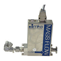
Digital Mass Flow Controller, Digital Mass Flow Meter
Brand:
MKS
| Category:
Controller
| Size: 0 MB
Table of Contents
Table of Contents
3
Safety Information
9
Symbols Used in this Instruction Manual
9
Safety Procedures and Precautions
10
Chapter 1: General Information
13
Introduction
13
Overview of Versions
13
Power Supply and Readout Units
14
Profibus Version
14
CE and EMC Requirements
14
Instruction Manual
15
Contents
15
Conventions
15
Designations and Names
15
Chapter 2: Shipment
17
General
17
Unpacking
17
Unpacking Checklist
17
Analog Units
17
Profibus Units
18
Label
19
Clean Room Packaging
19
Figure 1: Model Code Label
19
Chapter 3: Connectors and Control Elements
21
Analog Units
21
Figure 2: 1579A/B / 579A/B Side View
21
Figure 3: 1579A/B / 579A/B Connector Side
21
Autozero
22
Connector SETUP
22
Figure 4: 1579A/B / 579A/B Gas Inlet Side
22
Potentiometer ZERO
22
RESET Switch
22
Electrical Connector
23
1579A/B / 579A/B, Analog Unit
23
Figure 5: 15-Pol. Connector
23
Profibus Units
24
Figure 6: 1579A/B / 579A/B Side View
24
Figure 7: 1579A/B / 579A/B Connector Side
24
Address and Mode Switch A/B
25
Autozero
25
Figure 8: 1579A/B / 579A/B Gas Inlet Side
25
Potentiometer ZERO
25
RESET Switch
25
Status LED STS
25
Electrical Connectors
26
1579A/B / 579A/B, Profibus Units, Connector ANALOG
26
Figure 9: 9-Pol. Connector
26
1579A/B / 579A/B, Profibus Units, Connector PROFIBUS
27
Figure 10: Profibus Connector
27
Chapter 4: Operation
29
General Requirements
29
Environmental
29
Location and Orientation
30
Leak Integrity
30
Pressure Drop Test
30
Dimensions
31
Outline Dimensions
31
Figure 11: 1579A/B / 579A/B Dimensions (Side)
31
Mounting Holes
32
Figure 12: Dimensions (Inlet/Outlet Side)
32
Figure 13: Mounting Holes
32
Mounting Plate
33
Electrical Connections and Cables
33
Cables and Controllers by MKS
33
Figure 14: Mounting Plate
33
Table 1: MKS Cables
33
Power Supply / Readout Units of Other Manufacturers
34
Non MKS Cables
34
Finishing the Installation
34
Chapter 5: Operation (Analog Units)
35
Start up the Mass Flow Controller/Meter
35
Zero Adjust
36
Override the Control Valve
37
Priority of Commands
37
Chapter 6: Operation (Profibus Units)
39
Functions
39
Overview
39
Valve Override
40
Auto Zero
40
Alarm Limits
40
Temperature Measurement
40
Valve Drive Level
40
User Span / Gas Correction
41
User Zero
41
Filter
41
Gas Tables
41
Soft Start Rate
41
Start up the Mass Flow Controller
42
Zeroing the Flow Controller
43
Status LED STS
44
Address and Mode Switch A/B
44
Switch Assignment
44
Mode B
44
Figure 15: Address and Mode Switch Map A/B
44
Setting an Address
45
Mode a
45
Zero Modes
45
PROFIBUS Protocol
46
Data Interface
46
Send Data
47
Small Receive Data
48
Full Receive Data
49
Small Setup
50
Full Setup
51
Small Diagnostics
53
Full Diagnostics
54
Calibration Table
56
PROFIBUS Setup
57
GSD Files Usage
57
Chapter 7: Theory of Operation
59
Technique of Measurement and Control, Electronics
59
Flow Path
59
Measurement Technique
59
Control Circuitry
60
Control Valve
60
Chapter 8: Gas Correction Factor (GCF)
61
The Gas Correction Factor (GCF)
61
How to Calculate the GCF for Pure Gases
61
How to Calculate the GCF for Gas Mixtures
62
Note
62
Example
63
Mass Flow Rate at a Different Reference Temperature
63
Direct Reading of the Analog Output Signal
64
Figure 16: Voltage Divider
64
Chapter 9: MFC Sizing Guidelines
65
General
65
Determining the Flow Controller Range
66
Configurations for Low or High Differential Pressure
66
Chapter 10: Maintenance
67
General
67
Zero Adjustment
67
Checks and Recalibration
67
Profibus Support Kit
68
Customer Support
68
Troubleshooting
69
Table 2: Troubleshooting
69
Appendix A: Product Specifications
71
Specifications
71
Environmental Specifications
72
Electrical Specifications
72
Physical Specifications
73
Appendix B: Model Codes
75
Model Code
75
Type Number (XXXXA)
75
SEMI Gas Code (YYY)
76
Calibration Gas Flow Rate (ZZZ)
76
Fittings (F)
76
Valve (1)
77
Electrical/Communication Connector (C)
77
Seals (E)
77
Ordering Examples
78
To Order a Mass Flow Controller
78
To Order a Mass Flow Meter
78
Appendix C: Gas Correction Factors
79
Appendix D: Binary Code
83
Table 3: Binary Code
83
MKS Worldwide Calibration & Service Centers
85
Advertisement
Advertisement
Related Products
MKS 1579B
MKS 153D
MKS Mass-Flo 1500 Series
MKS Mass-Flo 1562A
MKS Mass-Flo 1559A
MKS MKS 153F
MKS 1253D
MKS 1150C
MKS Mass-Flo 1679B
MKS Mass-Flo 1160B
MKS Categories
Controller
Measuring Instruments
Transducer
Control Unit
Industrial Equipment
More MKS Manuals
Login
Sign In
OR
Sign in with Facebook
Sign in with Google
Upload manual
Upload from disk
Upload from URL