Table of Contents
Advertisement
Advertisement
Table of Contents

Related Manuals for Gira 1288 00


Summary of Contents for Gira 1288 00
- Page 1 Operating Instructions System Manual Video Control Device 1288 00...
-
Page 3: Table Of Contents
Table of contents System information ....................4 Installation scenario topologies................6 Structure of a flush-mounted door station with colour camera......8 Structure of a surface-mounted door station with colour camera....... 9 Structure of a home station with TFT display ............ 10 The door communication bus coupler ............... -
Page 4: System Information
System information The Gira door communication system operates with the volt- age type SELV. In systems with video components, up to 28 home stations and two door stations with colour cameras can be connected to the 2-wire bus. In systems with audio components, systems with up to 70 audio devices can be realised with certain system configurations, e.g. - Page 5 Cable lengths in video systems The maximum cable length between the colour camera and TFT display is 100 m. Cable lengths in audio systems The maximum total cable length (distributed among several wiring sections) is 700 m. A maximum of 30 devices may be connected to each wiring section.
-
Page 6: Installation Scenario Topologies
Installation scenario topologies Solution: "branching" Resistor = WS 3 Video Resistor = WS 2 Video Resistor = WS 1 Video Outdoor station ET = Floor-call button WS = Home station VV = Video distributor Control unit video For the "branching" solution, the terminating resistances of the home stations in the TFT display must be set to "Yes"... - Page 7 "Loop-through" solution Resistor = WS 3 Video Resistor = WS 2 Video Resistor = WS 1 Video Outdoor station ET = Floor-call button WS = Home station Control unit video A video distributor is not required for the "looping through" solution.
-
Page 8: Structure Of A Flush-Mounted Door Station With Colour Camera
Structure of a flush-mounted door station with colour camera The basic structure of a flush-mounted door station with the video function is presented in the example of the flush- mounted door station with video function with 3-gang call button and colour camera. 1 Door communication bus coupler 2 Audio connection cable (6 pole) 3 Video connection cable (2 pole) -
Page 9: Structure Of A Surface-Mounted Door Station With Colour Camera
Structure of a surface-mounted door station with colour camera The basic structure of a surface-mounted door station with the video function is presented in the example of the surface- mounted door station with colour camera and 3-gang call button. 1 Housing, bottom section 2 colour camera 3 Cable inlet 4 Connection terminals... -
Page 10: Structure Of A Home Station With Tft Display
Structure of a home station with TFT display The basic structure of a home station with video function is presented in the example of the Comfort home station with receiver and TFT display. 1 Receiver insert 2 Empty insert 3 Audio connection cable (6 pole) 4 Video connection cable (2 pole) 5 Door communication bus coupler 6 Display insert... - Page 11 With the door stations, for example, a mechanical bell button (NO contact) can be connected. This then acts like a call but- ton from the Gira door communication system during start-up and later operation. The maximum cable length between the mechanical button...
-
Page 12: The Door Communication Bus Coupler
Additional supply (ZV) The ZV terminals have two functions: 1. Power supply of call button illumination at the door sta- tions. The call buttons are constantly illuminated at the door sta- tions with colour camera. 2. Additional power supply for bus devices which can no longer be powered via the 2-wire bus. -
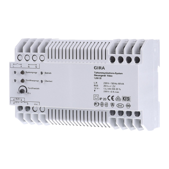
Page 13: The Video Control Device
The video control device The video control device is the main power supply of the Gira door communication system. The video control device assumes the following tasks in the Gira door communication system: • provision of the bus voltage (26 V DC ± 2 V) for the door communication system. - Page 14 • adjustable activation time of door opener.
-
Page 15: Displays And Operating Elements Of Video Control Device
Displays and operating elements of video control device "Betrieb" indicator During trouble-free normal operation, only the green "Betrieb" LED illuminates. It indicates that the device is being supplied with power. "Überlast" indicator The video control device is equipped with an electronic over- load protection which protects the electronics of the control device against short-circuits and overloading on the bus line. -
Page 16: Connection Terminals Of Video Control Device
"Systemprogr." button If the "Systemprogr." button is pressed for 3 seconds, the door communication system is switched to programming mode. The yellow LED next to the programming button indi- cates the active programming mode via flashing (see Page 19). "Türöffnerprogr." button The "Türöffnerprogr."... - Page 17 Output for powering of the Gira door communication bus with regulated direct current (26 V DC ± 2 V, 700 mA). (Door opener output 230 V AC/max. 2 A) A door opener which cannot be connected to the "12 VAC" terminals due to its electrical val- ues (e.g.
-
Page 18: Mounting Of Video Control Device
Mounting of video control device Attention Installation and mounting of electrical devices may only be carried out by a qualified electrician. For installation protected from dripping and sprayed water, mount the control device to a top-hat rail in the distribution. The mains and bus connection is made via screw terminals. -
Page 19: Start-Up
Switching system to programming mode The Gira door communication system is switched to program- ming mode for start-up: 1. Press the "Systemprogr." button on the control device for 3 seconds. 3 The yellow LED next to the programming button flashes (flash frequency: 1 Hz) after the button is pressed and indi- cates the active programming mode. -
Page 20: One-Family House: Assigning Door Station Call Button To Home Station
One-family house: Assigning door station call button to home station To assign a door station call button to a home station, proceed as follows: 1. Press the "System prog." button on the control device for 3 seconds to start programming mode (see Page 19). 2. -
Page 21: House Divided Into Several Flats: Assigning Door Station Call Buttons To Home Stations
House divided into several flats: Assigning door station call buttons to home stations To assign the door-station call buttons to the respective home stations, please proceed as follows: 1. Press the "System prog." button on the control device for 3 seconds to start programming mode (see Page 19). 2. - Page 22 4. Go to the home station whose call button is the second one you pressed at the door station. Press the button on this home station for 3 seconds until you hear a short acknowledgement tone. 3 A long acknowledgement tone indicates successful assignment.
-
Page 23: Assigning Door Opener
Assigning door opener The door opener connected to the control device is assigned to the "main" door station. It is activated if the button at a home station is pressed spontaneously, even without any previous conversation. The door opener of a "back/side" door is connected to the switching actuator. - Page 24 Assigning door opener of a "side/back" door The door opener connected to the switching actuator is pro- grammed at the respective door station as follows: 1. Press the "System prog." button on the control device for 3 seconds to start programming mode (see Page 19). 2.
-
Page 25: Automatic Door Opener
Automatic door opener Hands-free feature and Comfort home station The function "automatic door opener" is only supported by the hands-free feature home station and the Comfort home station with receiver. The automatic door opener is, for example, used in doctor's offices when after pressing a door-station call button, the door opener is to be automatically operated. - Page 26 If the "automatic door opener" function is enabled, you can activate the automatic door opener as necessary on the home station as follows: Activating automatic door opener 1. Simultaneously press the buttons on the home station for approx. 3 seconds to activate the automatic door opener.
-
Page 27: Assigning Home Station Via Floor-Call Button
Assigning home station via floor-call button If you cannot access the home during start-up, you can also assign the home station via a connected floor-call button: 1. Press the "System prog." button on the control device for 3 seconds to start programming mode (see Page 19). 2. -
Page 28: Assigning Several Home Stations To A Call Button
Assigning several home stations to a call button If several home stations are to be called simultaneously when a door station call button is pressed, a call button can be assigned to several (max. 3) home stations as follows: 1. Press the "System prog." button on the control device for 3 seconds to start programming mode (see Page 19). -
Page 29: Assigning Several Home Stations To A Floor-Call Button
Assigning several home stations to a floor-call button If several home stations are to be called simultaneously when a floor-call button is pressed, a floor-call button can be assigned to several (max. 3) home stations as follows: 1. Press the "System prog." button on the control device for 3 seconds to start programming mode (see Page 19). -
Page 30: Assigning Call Button For Home Station To A Home Station (Internal Call)
Assigning call buttons for home station to a home station (internal call) You can implement the so-called internal call function with the optional call button for home stations. A voice connection between two home stations can be established via the inter- nal call. -
Page 31: Deleting All Assignments To A Home Station
Deleting all assignments to a home station A home station which as already been assigned is deleted as follows: 1. Press the "System prog." button on the control device for 3 seconds to start programming mode (see Page 19). 2. Press the button on the home station for which the assignment is to be deleted for 6 seconds. -
Page 32: Deleting Assignment Of The Door Opener
Deleting assignment of door opener Door opener at video control device To delete an existing assignment between the door opener connected at the control device and the door station, proceed as follows: 1. Press the "System prog." button on the control device for 3 seconds to start programming mode (see Page 19). -
Page 33: Replacement Of Defective Call Button Top Units Of A Flush-Mounted Door Station
Replacement of defective call button top units of a flush-mounted door station You can replace defective door station call button top units at a flush-mounted door station without having to reprogram the assignments: 1. Replace all defective call button top units with new ones. 2. -
Page 34: Use Of The Video Distributor / Configuration Of The Terminating Resistance
Use of the video distributor - configuration of the terminating resistance In order for the cable ends of the branches to have a defined terminating resistance, you can activate or deactivate the terminating resistance of a home station at the TFT display. To activate it, go to the menu item "Widerstand"... - Page 35 2. Rule: Activate the terminating resistance of the last home station for looping through Resistor = Resistor = Resistor = WS 3 Video WS 2 Video WS 1 Video Outdoor station Control unit video Home stations without the video function can simply be inte- grated into the line and do not affect the setting of the last home station.
- Page 36 3. Rule: A video distributor is necessary at the branch end for an audio home station If a home station without the video function is located at the end of a cable line, a video distributor must be inserted. Resistor = Resistor = WS 3 Audio WS 2 Video...
- Page 37 4. Rule: If the video signal runs through 3 or more video distributors, a suppressor must be used. If the video signal runs through three or more video distribu- tors in a topology, a suppressor must be connected at the furthest home station with TFT colour display.
-
Page 38: Connection Of Several Colour Cameras
Connection of several colour cameras When using several door stations with colour cameras, the door stations are linked via video distributors. In this case, note that the output lines of the video distributor may not exceed 30 cm. TS 1 TS 2 TS 3 max. -
Page 39: Led Indicators On Bus Devices
LED indicators on BUS devices The LEDs of the hands-free feature, Comfort with receiver, surface-mounted hands-free feature and surface-mounted gong home stations indicate the system status: LED/button System status Programming mode active – call-buttons and/ flashes or gong not yet assigned Programming mode active –... -
Page 40: Acknowledgement Tones Of Bus Devices
Acknowledgement tones of Bus devices In programming mode, the following conditions are indicated using acknowledgement tones: Acknowl- Meaning edgement tone Short tone • During assignment: release button • While deleting: no meaning, continue to hold down button Long tone • During assignment: call button was as- signed successfully •... -
Page 41: Table For Start-Up Documentation
Table for start-up documentation Call button Home station (Name / Location / Floor) Taught-in (Number / Name) Meier 2nd floor left, living room... -
Page 42: Warranty
The warranty is provided in accordance with statutory requirements via the specialist trade. Please submit or send faulty devices postage paid together with an error description to your responsible salesperson (specialist trade/installation company/electrical specialist trade). They will forward the devices to the Gira Service Center. - Page 44 Gira Giersiepen GmbH & Co. KG Elektro-Installations- Systeme Postfach 1220 42461 Radevormwald Deutschland Tel +49 (0) 21 95 / 602 - 0 Fax +49 (0) 21 95 / 602 - 191 www.gira.de info@gira.de...
Need help?
Do you have a question about the 1288 00 and is the answer not in the manual?
Questions and answers