
Subscribe to Our Youtube Channel
Related Manuals for Gira 1269 65


Summary of Contents for Gira 1269 65
- Page 1 Operating Instructions Surface-mounted outdoor station with colour camera and call push button 1-gang 1269 65/66/67 Surface-mounted outdoor station with colour camera and call push button 2/3-gang 1270 65/66/67...
-
Page 3: Table Of Contents
Table of contents Device description ..............4 Functional scope of the colour camera ........5 Selection of the installation site..........6 Mounting ................. 7 Start-up..................8 Range of coverage of the colour camera ........9 Setting range of coverage ............10 Operation.................12 Changing the label plates ............13 Technical data................. -
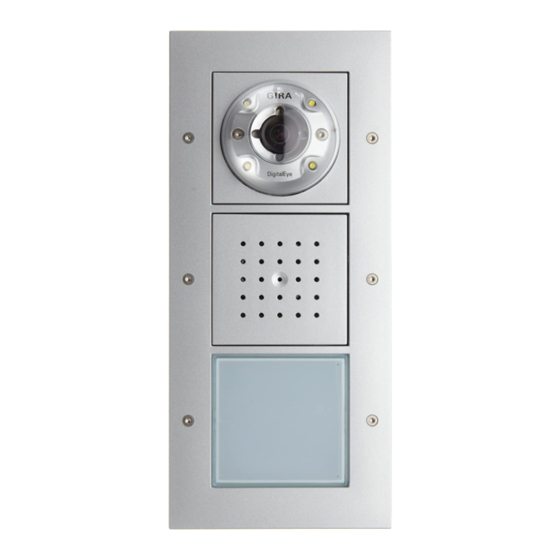
Page 4: Device Description
Device description The surface-mounted outdoor station with colour camera is a prefabricated unit and is part of the Gira door communication system. The basic structure of a surface-mounted outdoor station is pre- sented in the example of the surface-mounted outdoor station with colour camera and call push button 2/3-gang. -
Page 5: Functional Scope Of The Colour Camera
Functional scope of the colour camera The colour camera of the flush-mounted outdoor station has the following product features: Automatic day/night switching The camera switches from daytime operation (colour presenta- tion) to night mode (black and white presentation) and back again at an ambient brightness of 1 lux. -
Page 6: Selection Of The Installation Site
Selection of the installation site The selection of the installation site and good illumination are critical for good picture quality. No backlighting Do not point the camera toward strong background lighting, such as streetlamps or yard illumination. Prevent strong sunlight from hitting the lens. Picture background Avoid pointing the camera toward extremely light picture back- grounds and backgrounds with stark contrasts. -
Page 7: Mounting
Mounting Attention Installation and mounting of electrical devices may only be car- ried out by a qualified electrician. Movable PCB The PCB can be pushed downward for mounting and for con- nection of the bus line. 1. Select the installation site. The cable duct leading into the bottom section of the housing is used for line guidance. -
Page 8: Start-Up
7. Push the PCB into the upper position. 8. Set the camera lens in the desired direction (see "Setting range of coverage", Page 10). 9. Remove the protective film on the lens. 10.Attach the camera cover. 11.Ensure proper seating of the speech cover and colour cam- era sealing rings. -
Page 9: Range Of Coverage Of The Colour Camera
Range of coverage of the colour camera The CCD sensor element of the colour camera has an angular coverage of 100°. If this angular coverage is not sufficient for your installation sce- nario, you can swivel the area to be captured by 20° in all direc- tions. -
Page 10: Setting Range Of Coverage
Setting range of coverage Protective lens film The protective film on the lens of the colour camera protects the sensitive optics from scratches and soiling. Leave this film on the lens as long as possible and avoid touch- ing the lens directly after the protective film has been removed. - Page 11 4. At the TFT display of the connected home sta- tion, check whether the set angle of the camera lens is adjusted properly and whether the view of a person in front of the door is optimal. 5. Lock the lens carrier by tightening both Torx screws again....
-
Page 12: Operation
Operation Volume setting The volume can be set separately at each outdoor station. The volume setting must be made by two people. 1. Start programming mode at the control unit by pressing the "Systemprogr." button for 3 seconds until the yellow LED next to the button starts flashing. -
Page 13: Changing The Label Plates
1. Carefully lift the call push button cover, e.g. with a screwdriver. 2. Change the label plate. 3. Replace the call push button cover and press on it firmly. Suitable label plates can be obtained with the optional Gira label- ling software and the appropriate Gira labelling sheets. -
Page 14: Technical Data
Technical data Power supply: 2 cameras via video control unit 3rd and 4th camera via external additional supply (24 V DC) Connections of camera insert: 2 system bus plug strips 1 video plug strip 1 plug strip connection for future applications Image capture element: CCD sensor 1/3"... -
Page 15: Acceptance Of Guarantee
The warranty is provided in accordance with statutory require- ments via the specialist trade. Please submit or send faulty devices postage paid together with an error description to your responsible salesperson (specialist trade/installation company/electrical specialist trade). They will forward the devices to the Gira Service Center. - Page 16 Gira Giersiepen GmbH & Co. KG Elektro-Installations- Systeme Postfach 1220 42461 Radevormwald Deutschland Tel +49 (0) 21 95 / 602 - 0 Fax +49 (0) 21 95 / 602 - 191 www.gira.de info@gira.de...
Need help?
Do you have a question about the 1269 65 and is the answer not in the manual?
Questions and answers