Table of Contents
Advertisement
Quick Links
Advertisement
Table of Contents

Related Manuals for Newport Pt32


Summary of Contents for Newport Pt32
-
Page 3: Table Of Contents
Introduction PLATINUM Series Controllers User’s Guide Table of Contents, Figures and Tables Introduction ............................7 Description ............................ 7 Safety Considerations ........................... 8 Wiring Instructions ..........................9 Back Panel Connections ........................ 9 Connecting Power ........................10 Connecting Inputs ........................11 Connecting Outputs ........................13 PLATINUM Series Navigation ...................... - Page 4 Introduction PLATINUM Series Controllers User’s Guide 6.8.3 Manual Temperature Calibration Offset and Slope Adjustment (INIt > t.CAL > 2.PNt) ..41 6.8.4 Temperature Ice Point Calibration (INIt > t.CAL > ICE.P) ............ 42 Save Current Configuration for All Parameters to a File (INIt > SAVE) ........42 6.10 Load a Configuration for All Parameters from a File (INIt >...
- Page 5 Introduction PLATINUM Series Controllers User’s Guide Normal Run Mode (oPER > RUN) ....................62 Change Setpoint 1 (oPER > SP1) ....................62 Change Setpoint 2 (oPER > SP2) ....................63 Manual Mode (oPER > MANL) ....................63 Pause Mode (oPER > PAUS) ......................64 Stop Process (oPER >...
- Page 6 Introduction PLATINUM Series Controllers User’s Guide Table 1 – 10-Pin Input Connector Wiring Summary ................... 11 Table 2 – Interfacing Sensors to the Input Connector ................11 Table 3 – Output Type Designations for Base Output Connector.............. 13 Table 4 – 8 Pin Output/Power Connector Wiring Summary by Configuration........... 13 Table 5 –...
-
Page 7: Introduction
Introduction PLATINUM Series Controllers User’s Guide 1. Introduction 1.1 Description The PLATINUM Series Controller offers unparalleled flexibility in process measurement. While the controller is extremely powerful and versatile, great care has gone into designing a product that is easy to set up and use. Automatic hardware configuration recognition eliminates the need for jumpers. The PLATINUM Series Controller displays only the menu items associated with the system’s custom configuration. -
Page 8: Safety Considerations
Safety Considerations PLATINUM Series Controllers User’s Guide 2. Safety Considerations This device is marked with the international caution symbol. It is important to read this manual before installing or commissioning this device as it contains important information relating to Safety and EMC (Electromagnetic Compatibility). -
Page 9: Wiring Instructions
Wiring Instructions PLATINUM Series Controllers User’s Guide 3. Wiring Instructions 3.1 Back Panel Connections Ethernet Connector if EIP Option Installed Ethernet Communications Status LEDs if EIP Option Installed USB Connector (on side, shown with cable stub) 8-Pin Power / Base Outputs Connector 10-Pin Input Connector Figure 1 –... -
Page 10: Connecting Power
Wiring Instructions PLATINUM Series Controllers User’s Guide 8-Pin Power / Outputs Connector 10-Pin Input Connector Ethernet Connector if EIP Ethernet Communications Status USB Connector (on side, Option Installed LEDs if EIP Option Installed cable stub shown) Figure 3 – CN16Pt and CN32Pt Models: Back Panel Connections 3.2 Connecting Power Connect the main power connections to pins 7 and 8 of the 8-pin power / output connector as shown in Figure... -
Page 11: Connecting Inputs
Wiring Instructions PLATINUM Series Controllers User’s Guide 3.3 Connecting Inputs The 10-pin universal input connector assignments are summarized in Table 1. Table 2 provides detail for the specific types of sensors supported. All sensor selections are firmware-controlled (see 4.1 Input Configuration (INIt >... -
Page 12: Figure 5 – Rtd Wiring Diagram
Wiring Instructions PLATINUM Series Controllers User’s Guide RTD (100 Ω) 4-WIRE RTD (100 Ω) 3-WIRE RTD (100 Ω) 2-WIRE (requires pin 1 to be jumped to pin 4) Figure 5 – RTD Wiring Diagram 0–24 mA Internal Excitation External Excitation Internal Figure 6 –... -
Page 13: Connecting Outputs
Wiring Instructions PLATINUM Series Controllers User’s Guide 3.4 Connecting Outputs The PLATINUM Series supports 7 different types of outputs with the model number numeric designations summarized in Table 3. The unit comes preconfigured with up to 3 outputs (up to 6 outputs with 1/8 DIN models). -
Page 14: Table 5 – 6 Pin Output Expansion Board Connector Wiring Summary By Configuration
Wiring Instructions PLATINUM Series Controllers User’s Guide Table 5 – 6 Pin Output Expansion Board Connector Wiring Summary by Configuration. Output Expansion Board Pin Number Config. Description Isolated Analog V/C+ IDC, IDC, Isolated Analog V/C+ SPST, SPST, Isolated Analog V/C+ SSR, SSR, Isolated Analog V/C+ Table 6 –... -
Page 15: Platinum Series Navigation
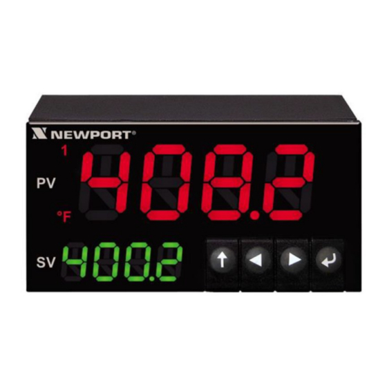
PLATINUM Series Navigation PLATINUM Series Controllers User’s Guide 4. PLATINUM Series Navigation Alarm Annunciators Process Value Negative Sign Temperature Units Program Buttons Setpoint Value Process Value Temperature Units Alarm Annunciators Program Buttons Figure 8 – PLATINUM Series Displays (CN8DPt and CN8EPt Shown) 4.1 Description of Button Actions The UP button moves up a level in the menu structure. -
Page 16: Level 1 Menu
PLATINUM Series Navigation PLATINUM Series Controllers User’s Guide 4.3 Level 1 Menu Initialization Mode: These settings are rarely changed after initial setup. They include INIt transducer types, calibration, etc. These settings can be password-protected. Programming Mode: These settings are frequently changed. They include Set points, PRoG Control Modes, Alarms, etc. -
Page 17: Complete Menu Structure
Complete Menu Structure PLATINUM Series Controllers User’s Guide 5. Complete Menu Structure 5.1 Initialization Mode Menu (INIt) The following table maps the Initialization Mode (INIt) navigation: Level Level Level Level Level Level Level Notes INPt t.C. Type K thermocouple Type J thermocouple Type T thermocouple Type E thermocouple Type N thermocouple... - Page 18 Complete Menu Structure PLATINUM Series Controllers User’s Guide Level Level Level Level Level Level Level Notes dIFF Differential between AIN+ and AIN- RtLO Ratiometric between AIN+ and AIN- +-0.1 Process input range: -0.1 to +0.1 V Note: The +- 0.05 input supports dIFF and RtIO tYPE +-.05 tYPE dIFF...
- Page 19 Complete Menu Structure PLATINUM Series Controllers User’s Guide Level Level Level Level Level Level Level Notes bRGt HIGH High display brightness Medium display brightness Low display brightness ECtN Excitation voltage: 5 V 10 V 10 V 12 V 12 V 24 V 24 V for AC units only Excitation off...
- Page 20 Complete Menu Structure PLATINUM Series Controllers User’s Guide Level Level Level Level Level Level Level Notes 2400 2,400 Bd 1200 1,200 Bd 57.6 57,600 Bd 115.2 115,200 Bd PRty Odd parity check used EVEN Even parity check used NoNE No parity bit is used Parity bit is fixed as a zero dAtA 8bIt...
-
Page 21: Programming Mode Menu (Prog)
Complete Menu Structure PLATINUM Series Controllers User’s Guide 5.2 Programming Mode Menu (PRoG) The following table maps the Programming Mode (PRoG) navigation: Level Level Level Level Level Notes ____ Process goal for PID, default goal for oN.oF ASbo Setpoint 2 value can track SP1, SP2 is an absolute value dEVI SP2 is a deviation value ALM.1... - Page 22 Complete Menu Structure PLATINUM Series Controllers User’s Guide Level Level Level Level Level Notes AUto StRt Initiates autotune after StRt confirmation GAIN ____ Manual Proportional Band setting ____ Manual Integral Factor setting ____ Manual Derivative Factor setting ____ Low clamping limit for Pulse, Analog Outputs ____ High clamping limit for Pulse, Analog Outputs AdPt...
-
Page 23: Operating Mode Menu (Oper)
Complete Menu Structure PLATINUM Series Controllers User’s Guide Level Level Level Level Level Notes Soak events on for this segment 5.3 Operating Mode Menu (oPER) The following table maps the Operating Mode (oPER) navigation: Level Level Level Notes Normal Run Mode, process value displayed, SP1 in optional secondary display ____ Shortcut to change Setpoint 1, current Setpoint 1 value in main display ____... -
Page 24: Reference Section: Initialization Mode (Init)
Reference Section: Initialization Mode (INIt) PLATINUM Series Controllers User’s Guide 6. Reference Section: Initialization Mode (INIt) Use Initialization Mode to set the following parameters and perform the following functions: Reference Section: Initialization Mode (INIt) ..................24 Input Configuration (INIt > INPt) ....................24 TARE (INIt >... -
Page 25: Resistance Temperature Detector (Rtd) Input Type (Init > Inpt > Rtd)
Reference Section: Initialization Mode (INIt) PLATINUM Series Controllers User’s Guide 6.1.2 Resistance Temperature Detector (RTD) Input Type (INIt > INPt > Rtd) Select Rtd as the input type. Factory default configuration settings are three-wire, 100 Ω, using the European standard 385 curve. Note that the 392 and 3916 curves are only available for 100 Ω... -
Page 26: Process Input Type Configuration (Init > Inpt > Proc)
Reference Section: Initialization Mode (INIt) PLATINUM Series Controllers User’s Guide 6.1.4 Process Input Type Configuration (INIt > INPt > PRoC) Select Process (PRoC) as the input type. Then select the process input range and scale it. If stopped after selecting the PRoC input type, the last selected input range and scaling is used. Navigate to the voltage or current range of the process input. - Page 27 Reference Section: Initialization Mode (INIt) PLATINUM Series Controllers User’s Guide Select the scaling parameter to change. For manual inputs, set the selected scaling parameter to the desired value. Confirm the value for the selected scaling parameter in Manual Mode (MANL), or read and accept the input signal for either IN.1 or IN.2 in Live Mode (LIVE).
- Page 28 Reference Section: Initialization Mode (INIt) PLATINUM Series Controllers User’s Guide 6.1.4.1 Ratiometric Inputs Ratiometric inputs allow applying an external reference voltage (Vref) used by the Analog / Digital converter and the measured signal level directly proportional to the reference voltage. The external reference voltage must be in the range of 1.5 –...
- Page 29 Reference Section: Initialization Mode (INIt) PLATINUM Series Controllers User’s Guide 6.1.4.2 Bridge Inputs Ratiometric inputs are widely used for bridge inputs as found in load cell and pressure sensors because any fluctuations in the excitation voltage are eliminated in the final reading. The input is configured as a ratiometric input, where the voltage difference between terminals 2 (AIN+) and 3 (AIN-) is measured with respect to the externally applied voltage reference applied between terminal 1 (ARTN) and terminal 4 (APWR).
- Page 30 Reference Section: Initialization Mode (INIt) PLATINUM Series Controllers User’s Guide 6.1.4.3 Bridge (Ratiometric) Input Scaling To calibrate to a specific bridge device, the user must provide two known loads and enter the corresponding values. This allows the device to calculate a straight line correction: Weight = Input Reading X Gain + Offset Scaling operations allow translating source (input) signals to scaled output signal using a linear translation defined by a SLOPE (or gain) and an OFFSET.
-
Page 31: Tare (Init > Tare)
Reference Section: Initialization Mode (INIt) PLATINUM Series Controllers User’s Guide 6.2 TARE (INIt > tARE) Select TARE (tARE) to configure the tare option. Navigate to the desired setting. Settings include the following: dSbL – No TARE option is enabled ... - Page 32 Reference Section: Initialization Mode (INIt) PLATINUM Series Controllers User’s Guide In many applications a single Gain and Offset as provided by the Scaling adjustment on process inputs can be used that supports a direct linearization between the input signal and the required reading. For more complex applications, the relationship between the input value and the desired reading is not linear across the entire range of inputs.
-
Page 33: Display Reading Formats (Init > Rdg)
Reference Section: Initialization Mode (INIt) PLATINUM Series Controllers User’s Guide 6.4 Display Reading Formats (INIt > RdG) Select Reading Formats (RdG) to configure the front panel display. Navigate to the desired setting. Settings include the following: dEC.P – Decimal-point format (entry point) ... -
Page 34: Display Rounding (Init > Rdg > D.rnd)
Reference Section: Initialization Mode (INIt) PLATINUM Series Controllers User’s Guide 6.4.3 Display Rounding (INIt > RdG > d.RNd) Select the Display Rounding (d.Rnd) option. The Display Rounding parameter determines the minimum change in value required to cause the display to update. For example, if the d.RNd value is set to 5.0, the displayed values will be 0, 5, 10…. -
Page 35: Annunciator Settings (Init > Rdg > Ann.1/Ann.2)
Reference Section: Initialization Mode (INIt) PLATINUM Series Controllers User’s Guide 6.4.5 Annunciator Settings (INIt > RdG > ANN.1/ANN.2) Select the Annunciator 1 (ANN.1) parameter. This controls which Alarm or output status activates the “1” annunciator on the front display. In general, the default values for both annunciators should be used (status for Alarm configuration 1 for annunciator 1 and status for Alarm configuration 2 for annunciator 2). -
Page 36: Excitation Voltage (Init > Ectn)
Reference Section: Initialization Mode (INIt) PLATINUM Series Controllers User’s Guide 6.5 Excitation Voltage (INIt > ECtN) Select the Excitation Voltage (ECtN) parameter. Navigate to the correct setting. Settings include the following: 5 V – 5 Volt excitation voltage (factory default) ... -
Page 37: Address (Init > Comm > Usb, Ethn, Ser > Addr)
Reference Section: Initialization Mode (INIt) PLATINUM Series Controllers User’s Guide 6.6.1.1 ASCII Parameters (INIt > CoMM > USb, EtHN, SER > PRot > oMEG) Select oMEG to configure Omega ASCII mode communications parameters. These configuration settings are the same for USB, Ethernet, and Serial communications. Navigate to the desired parameter. -
Page 38: Serial Communications Parameters (Init > Comm > Ser >C.par)
Reference Section: Initialization Mode (INIt) PLATINUM Series Controllers User’s Guide 6.6.3 Serial Communications Parameters (INIt > CoMM > SER >C.PAR) Select C.PAR. Then, select individual parameters to configure the serial communications. Navigate to the correct setting. Settings include the following: ... -
Page 39: Safety Features (Init > Sfty)
Reference Section: Initialization Mode (INIt) PLATINUM Series Controllers User’s Guide 6.6.3.4 Data Bits (INIt > CoMM > SER > C.PAR > dAtA) Select the number of Data Bits (dAtA). Navigate to the desired setting. Settings include the following: 8bIt – 8 bits used per data character (factory default) ... -
Page 40: Setpoint Limits (Init > Sfty > Sp.lm)
Reference Section: Initialization Mode (INIt) PLATINUM Series Controllers User’s Guide 6.7.3 Setpoint Limits (INIt > SFty > SP.LM) Select Setpoint Limits (SP.LM) to set limits on the values that can be used for the all Setpoints. Navigate to the desired setting. Settings include the following: ... -
Page 41: Manual Temperature Calibration (Init > T.cal)
Reference Section: Initialization Mode (INIt) PLATINUM Series Controllers User’s Guide 6.8 Manual Temperature Calibration (INIt > t.CAL) Select the Manual Temperature Calibration (t.CAL) submenu. This parameter allows manual adjustment to the thermocouple, RTD, or Thermistor calibration curves provided with the unit. -
Page 42: Temperature Ice Point Calibration (Init > T.cal > Ice.p)
Reference Section: Initialization Mode (INIt) PLATINUM Series Controllers User’s Guide 6.8.4 Temperature Ice Point Calibration (INIt > t.CAL > ICE.P) Select ICE.P to calibrate the zero point for the temperature sensor. This function basically operates the same as a 1.PNT offset adjustment restricted to a measurement at the freezing point of water. -
Page 43: Update Firmware Revision (Init > Ver.u)
Reference Section: Initialization Mode (INIt) PLATINUM Series Controllers User’s Guide 6.12 Update Firmware Revision (INIt > VER.U) Select the Update Firmware Revision (VER.U) function. Note that updating the firmware will reset the unit to factory defaults. To keep all configuration settings, save them before installing new firmware. -
Page 44: Reference Section: Programming Mode (Prog)
Reference Section: Programming Mode (PRoG) PLATINUM Series Controllers User’s Guide 7. Reference Section: Programming Mode (PRoG) Use Programming Mode to set the following parameters and perform the following functions: Reference Section: Programming Mode (PRoG) ................44 Setpoint 1 Configuration (PRoG > SP1) ..................44 Setpoint 2 Configuration (PRoG >... -
Page 45: Alarm Mode Configuration (Prog > Alm.1, Alm.2)
Reference Section: Programming Mode (PRoG) PLATINUM Series Controllers User’s Guide 7.3 Alarm Mode Configuration (PRoG > ALM.1, ALM.2) Select Alarm Configuration 1 (ALM.1) or Alarm Configuration 2 (ALM.2) in order to set up, change, enable, or disable Alarms. Either or both Alarms can be assigned to trigger display color changes, annunciators, and / or outputs. -
Page 46: Absolute Or Deviation Alarm (Prog > Alm.1, Alm.2 > Type > Ab.dv)
Reference Section: Programming Mode (PRoG) PLATINUM Series Controllers User’s Guide Setting Absolute (AbSo) Deviation (d.SP1) Deviation (d.SP2) AboV > ALR.H > SP1 + ALR.H > SP2 + ALR.H bELo < ALR.L < SP1 - ALR.L < SP2 - ALR.L HI.Lo. <... -
Page 47: Alarm Low Reference (Prog > Alm.1, Alm.2 > Type > Alr.l)
Reference Section: Programming Mode (PRoG) PLATINUM Series Controllers User’s Guide 7.3.4 Alarm Low Reference (PRoG > ALM.1, ALM.2 > tyPE > ALR.L) Select the Alarm Low Reference (ALR.L) parameter. Set the Alarm Low Reference value. Confirm the value. 7.3.5 Alarm Color (PRoG > ALM.1, ALM.2 > A.CLR) Select the Alarm Color (A.CLR) parameter. -
Page 48: Alarm Latching (Prog > Alm.1, Alm.2 > Ltch)
Reference Section: Programming Mode (PRoG) PLATINUM Series Controllers User’s Guide 7.3.7 Alarm Latching (PRoG > ALM.1, ALM.2 > LtCH) Select the Alarm Latching (LtCH) parameter. Navigate to the desired option. Options include the following: No – Alarm does not latch (factory default); the Alarm turns off when the Process Value returns to a non-Alarm condition ... -
Page 49: Alarm Off Delay (Prog > Alm.1, Alm.2 > De.of)
Reference Section: Programming Mode (PRoG) PLATINUM Series Controllers User’s Guide 7.3.11 Alarm Off Delay (PRoG > ALM.1, ALM.2 > dE.oF) Select the Alarm Off Delay (dE.oF) parameter. Set the number of seconds to delay cancelling the Alarm. (The default is 0.) This setting can be used to prevent Alarm chatter. -
Page 50: Output Channel Mode (Prog > Out1-Out6 > Mode)
Reference Section: Programming Mode (PRoG) PLATINUM Series Controllers User’s Guide 7.4.1 Output Channel Mode (PRoG > oUt1–oUt6 > ModE) Select Output Channel Mode (ModE) to configure the specified output. Navigate to the desired setting. Settings include the following: – Turn off the output channel (factory default) ... - Page 51 Reference Section: Programming Mode (PRoG) PLATINUM Series Controllers User’s Guide For ACtN, select the correct setting. Settings include the following: RVRS – Off when Process Value is > Setpoint, and on when Process Value is < Setpoint (e.g., heating); deadband is applied below Setpoint (factory default) ...
-
Page 52: Output Cycle Pulse Width (Prog > Out1-Out6 > Cycl)
Reference Section: Programming Mode (PRoG) PLATINUM Series Controllers User’s Guide 7.4.1.8 Set Output to Soak Event Mode (PRoG > oUt1– oUt6 > ModE > SE.oN) Activate Output to Soak Event Mode (SE.oN) during Soak segments in Ramp and Soak programs when the Soak Event flag is set for that Soak segment. This can be used to turn on auxiliary devices such as fans or stirrers. -
Page 53: Pid Configuration (Prog > Pid.s)
Reference Section: Programming Mode (PRoG) PLATINUM Series Controllers User’s Guide 7.5 PID Configuration (PRoG > PId.S) Select PId.S to configure the PID control settings. These settings apply to all outputs that have had their Control Mode set to PID (7.4.1.2 PID Control Mode (PRoG > oUt1-oUt6 > ModE > PId)). -
Page 54: Pid Gain Settings (Prog > Pid > Gain)
Reference Section: Programming Mode (PRoG) PLATINUM Series Controllers User’s Guide 7.5.4 PID Gain Settings (PRoG > PId > GAIN) Select Gain (GAIN) to manually adjust the PID factors. Setting I to zero sets the controller for “PD” control, setting d to zero sets the controller for “PI” control, and setting both I and d to zero sets the controller for “proportional”... -
Page 55: Adaptive Tuning (Prog > Pid > Adpt)
Reference Section: Programming Mode (PRoG) PLATINUM Series Controllers User’s Guide 7.5.7 Adaptive Tuning (PRoG > PId > AdPt) Select the Adaptive Tuning (AdPt) parameter. Navigate to the desired setting. When adaptive tuning is enabled, the PID parameters are continually optimized based on the process input changes caused by the current output control parameters. -
Page 56: Cascade Control Using Remote Setpoint
Reference Section: Programming Mode (PRoG) PLATINUM Series Controllers User’s Guide 7.6.1 Cascade Control using Remote Setpoint The remote Setpoint feature of the PLATINUM Series controllers can be used in a variety of applications where Setpoints can be sent to the controllers from remote devices such as a manual pots, transmitters, computers, etc. -
Page 57: Multi-Ramp/Soak Mode Parameters (Prog > M.rmp)
Reference Section: Programming Mode (PRoG) PLATINUM Series Controllers User’s Guide 7.7 Multi-Ramp/Soak Mode Parameters (PRoG > M.RMP) Select Multi-Ramp/Soak Mode (M.RMP) for activation and configuration to store, and load up to 99 Ramp/Soak programs. Each program can have up to 8 Ramps and 8 Soaks including the ability to activate auxiliary (non-control) outputs during any or all Ramp and Soak segments. -
Page 58: Select Program (Prog > M.rmp > S.prg)
Reference Section: Programming Mode (PRoG) PLATINUM Series Controllers User’s Guide 7.7.2 Select Program (PRoG > M.RMP > S.PRG) Select the Select Program (S.PRG) parameter. The current profile for the selected program number will be loaded and can be used as is or modified. Set the number (1–99) corresponding to the Ramp/Soak profile to be loaded for use or editing. -
Page 59: Number Of Segments (Prog > M.rmp > N.seg)
Reference Section: Programming Mode (PRoG) PLATINUM Series Controllers User’s Guide Navigate to the desired setting. Settings include the following: StOP – Enter standby mode displaying RUN at the completion of this program. HOLd – Hold at the final soak setpoint at the completion of this program. ... -
Page 60: More On Multi-Ramp/Soak Programming
Reference Section: Programming Mode (PRoG) PLATINUM Series Controllers User’s Guide 7.7.8 More on Multi-Ramp/Soak Programming 7.7.8.1 Overview A key feature of the Ramp and Soak mechanism is provided by the ability to ‘link’ ramp/soak segments together to create a chain of sequences. This allows sequences of up to 792 Ramp/Soak pairs to be defined. -
Page 61: Figure 15. Ramp & Soak Current Process Variable
Reference Section: Programming Mode (PRoG) PLATINUM Series Controllers User’s Guide These controllers provide a multi-segment/multi-profile Ramp and Soak mechanism with the additional ability to link multiple profiles together to implement extended sequences. Although the term ‘RAMP’ is used to indicate the process variable change, there is no restrictions on the direction of change. -
Page 62: Reference Section: Operating Mode (Oper)
Reference Section: Operating Mode (oPER) PLATINUM Series Controllers User’s Guide 8. Reference Section: Operating Mode (oPER) Operating Mode is used to activate the unit’s monitoring and controlling functions. It also allows shortcut access to the Setpoint parameters while still running. Use Operating Mode to set the following parameters and perform the following functions: Reference Section: Operating Mode (oPER) .................. -
Page 63: Change Setpoint 2 (Oper > Sp2)
Reference Section: Operating Mode (oPER) PLATINUM Series Controllers User’s Guide 8.3 Change Setpoint 2 (oPER > SP2) Select the Change Setpoint 2 (SP2) parameter. This function allows Setpoint 2 to be changed while remaining in RUN Mode. The current value for Setpoint 2 flashes in the main display. Setpoint 2 is only used for Alarms and as the cooling Setpoint in Heat/Cool Control Mode. -
Page 64: Pause Mode (Oper > Paus)
Reference Section: Operating Mode (oPER) PLATINUM Series Controllers User’s Guide 8.5 Pause Mode (oPER > PAUS) Select the Pause Operating Mode (PAUS) to pause the controller and hold the process input at its current value. If in a Multi-Ramp/Soak program, the timer for the current Ramp or Soak segment is paused as well. -
Page 65: Display Peak Reading (Oper > Peak)
Reference Section: Operating Mode (oPER) PLATINUM Series Controllers User’s Guide 8.9 Display Peak Reading (oPER > PEAk) Select Display Peak Reading (PEAk) to change the process value displayed to the highest reading since PEAk was last cleared. Clear the PEAk reading buffer. Return to RUN Mode or to displaying “RUN” depending on the Operating Safety parameter setting (6.7.2 Operating Mode Confirmation (INIt >... -
Page 66: Specifications
PLATINUM Series Controllers User’s Guide Specifications 9. Specifications 9.1 Inputs Input Types Thermocouple, RTD, Thermistor, Analog Voltage, Analog Current, Strain Current Input 4 to 20 mA, 0 to 24 mA Scalable Voltage Input ±50 mV, ±100 mV, ±1 V, ±10 Vdc Single Ended Scalable ±50 and ±100 mV differential and ratiometric inputs, scalable Thermocouple Input K, J, T, E, R, S, B, C, N... -
Page 67: Outputs
PLATINUM Series Controllers User’s Guide Specifications Ramp and Soak Up to 99 Saved Ramp and Soak programs Up to 8 Ramp and 8 Soak segments with individually selectable events per program Definable End Actions include program linking ... -
Page 68: General
PLATINUM Series Controllers User’s Guide Specifications 9.6 General Display 4-digit or 6-digit, 9-segment LED; red, green, and amber programmable colors for process variable, Setpoint, and temperature units 10.2 mm (0.40"): 32Pt, 16Pt, 16DPt (Dual Display) 21 mm (0.83"): 8Pt ... -
Page 69: Table 8 – Ranges And Accuracies For Supported Inputs
PLATINUM Series Controllers User’s Guide Specifications Table 8 – Ranges and Accuracies for Supported Inputs Input Type Description Range Accuracy Process/Strain Process Voltage ±50 mV, ±100 mV, ±1, ±10 Vdc 0.03% FS Process Process Current Scalable within 0 to 24 mA 0.03% FS J Type T/C Iron-Constantan... -
Page 70: Approvals Information
PLATINUM Series Controllers User’s Guide Approvals Information Approvals Information This product conforms to the EMC: 2014/30/EU (EMC Directive). Electrical Safety: 2014/35/EU (Low Voltage Directive) Safety requirements for electrical equipment for measurement, control, and laboratory Double Insulation; Pollution Degree 2 Dielectric withstand Test per 1 min ... - Page 72 M5451/N/1016...
Need help?
Do you have a question about the Pt32 and is the answer not in the manual?
Questions and answers