
Subscribe to Our Youtube Channel
Related Manuals for REXROTH VFC 5610


Summary of Contents for REXROTH VFC 5610
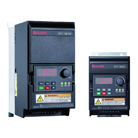
- Page 1 The Drive & Control Company Rexroth Frequency Converter VFC 3610 / VFC 5610 Quick Start Guide Edition 06 R912005518...
- Page 2 This document, as well as the data, specifications and other information set forth in it, are the exclusive property of Bosch Rexroth (Xi'an) Electric Drives and Controls Co., Ltd. It may not be reproduced or given to third parties without its consent.
-
Page 3: Table Of Contents
VFC 3610 / VFC 5610 Bosch Rexroth AG Table of Contents Table of Contents Page Mechanical Installation................Visual Check..................Ambient Conditions................Installation Conditions................2 Figures and Dimensions................. 3 1.4.1 Figures....................1.4.2 Dimensions.................... 1.4.3 DIN Rail Mounting.................. 5 Electric Installation................6 Overview of Electric Connections............ - Page 4 Bosch Rexroth AG VFC 3610 / VFC 5610 Table of Contents Page Parameter List..................3.3.1 Terminology and Abbreviation in Parameter List......... 3.3.2 Group b: System Parameters............... 24 b0: Basic system parameters............... 24 3.3.3 Group C: Power Parameters..............C0: Power control parameters............. 25 C1: Motor and system parameters............
-
Page 5: Mechanical Installation
VFC 3610 / VFC 5610 Bosch Rexroth AG Mechanical Installation 1 Mechanical Installation 1.1 Visual Check After unpacking the frequency converter, perform a thorough visual check. Check the following: The right device has been supplied ● The device has no damage ●... -
Page 6: Installation Conditions
Bosch Rexroth AG VFC 3610 / VFC 5610 Mechanical Installation 1.3 Installation Conditions The frequency converter must be installed vertically. If one frequency converter is arranged above another, make sure the upper limit of air temperature into the inlet is not exceeded (see 'Technical Data' in the Ope- rating Instructions). -
Page 7: Figures And Dimensions
VFC 3610 / VFC 5610 Bosch Rexroth AG Mechanical Installation 1.4 Figures and Dimensions 1.4.1 Figures Fig. 1-2: VFC x610 0K40...4K00 dimensions figure Fig. 1-3: VFC x610 5K50...18K5 dimensions figure 3/51 DOK-RCON04-VFC-X610***-QU06-EN-P... -
Page 8: Dimensions
: The complete type code for frequency converter is: ● VFCx610-xKxx-xPx-MNA-xx-NNNNN-NNNN, see "Appendix: Type Coding" in the Operating Instructions. E.g., type code for VFC 5610 5K50 (3P 400 VAC model) is: VFC5610-5K50-3P4-MNA-7P-NNNNN-NNNN. Model 3K00: ONLY available with VFC 3610. ●... -
Page 9: Din Rail Mounting
VFC 3610 / VFC 5610 Bosch Rexroth AG Mechanical Installation 1.4.3 DIN Rail Mounting Besides wall mounting with screws, Frequency Converter VFC x610 also pro- vides DIN rail mounting for models 0K40...7K50. Mounting buckle Disassembly handle Mounting rail Fig. 1-4: DIN rail mounting and disassembly... -
Page 10: Electric Installation
Bosch Rexroth AG VFC 3610 / VFC 5610 Electric Installation 2 Electric Installation 2.1 Overview of Electric Connections Fig. 2-1: Wiring diagram Information on cable size, fuse, screw torque, see chapter 2.2. ● Information on terminals, see chapter 2.3. ●... -
Page 11: Cable Specifications
VFC 3610 / VFC 5610 Bosch Rexroth AG Electric Installation 2.2 Cable Specifications 2.2.1 Power Connection Cable specification for international without USA / Canada ONLY USE copper wires of 90 ℃ or above with XLPE or EPR insu- ● lation according to IEC60364-5-52. -
Page 12: Cable Specification For Usa / Canada
Bosch Rexroth AG VFC 3610 / VFC 5610 Electric Installation Cable specification for USA / Canada ONLY USE copper wires of 75 ℃ or above according to UL 508C. ● It is recommended to use shielded cables to connect the motor. -
Page 13: Control Signal Connection
VFC 3610 / VFC 5610 Bosch Rexroth AG Electric Installation 2.2.2 Control Signal Connection The following requirements are applicable to signal connection: Flexible cables with wire end sleeves ● Cable cross-section: 0.2...0.75 mm ● Cable cross-section when using connectors with... -
Page 14: Terminals
Bosch Rexroth AG VFC 3610 / VFC 5610 Electric Installation 2.3 Terminals 2.3.1 Power Terminals Fig. 2-3: Power terminals (1P 200 VAC 0K40...2K20) Fig. 2-4: Power terminals (3P 400 VAC 0K40...4K00) Fig. 2-5: Power terminals (3P 400 VAC 5K50...18K5) Terminal... -
Page 15: Control Terminals
VFC 3610 / VFC 5610 Bosch Rexroth AG Electric Installation Fig. 2-6: Grounding and PE terminals 1: Grounding terminal for mains cables 2: Reserved for PE / shielding adapter (Order additionally) 3: Reserved for PE / shielding adapter (Order additionally) 4: Grounding terminal for motor cables 2.3.2 Control Terminals... -
Page 16: Control Terminals Description
Bosch Rexroth AG VFC 3610 / VFC 5610 Electric Installation Control terminals description Digital inputs Terminal Signal function Description Signal requirement Multi-function Inputs via opto-electric couplers: X1...X5 digital inputs See Group E1 24 VDC, 8 mA / 12 VDC, 4 mA Pulse input Pulse input: Max. -
Page 17: Digital Outputs
VFC 3610 / VFC 5610 Bosch Rexroth AG Electric Installation Digital outputs Terminal Signal function Description Signal requirement DO1a Open collector output: See Group E2 Open collector output or Max. 30 VDC, 50 mA pulse output DO1b COM is reference Pulse output Max. -
Page 18: Digital Input X1
Bosch Rexroth AG VFC 3610 / VFC 5610 Electric Installation Digital input X1...X5 NPN / PNP wiring Fig. 2-8: Digital input X1...X5 NPN / PNP wiring 14/51 DOK-RCON04-VFC-X610***-QU06-EN-P... -
Page 19: Digital Output Do1A, Do1B Load Pull-Up / Pull-Down Wiring
VFC 3610 / VFC 5610 Bosch Rexroth AG Electric Installation Digital output DO1a, DO1b load pull-up / pull-down wiring Fig. 2-9: Digital output DO1a, DO1b load pull-up / pull-down wiring Vcc supply can be provided externally or internally. For internal supply, ONLY USE +24 V and NEVER use +10 V or +5 V! Analog input terminals (AI1, AI2, +10 V, +5 V, Earth and GND) Fig. -
Page 20: Start-Up
Bosch Rexroth AG VFC 3610 / VFC 5610 Start-up 3 Start-up 3.1 LED Panel and Dust Cover 3.1.1 LED Panel Fig. 3-1: LED panel 16/51 DOK-RCON04-VFC-X610***-QU06-EN-P... -
Page 21: Dust Cover
VFC 3610 / VFC 5610 Bosch Rexroth AG Start-up 3.1.2 Dust Cover Fig. 3-2: Dust cover Frequency Converter VFC x610 are available with Dust Cover instead of LED Panel on demand. To operate frequency converters with Dust Cover, Order one LED Panel additionally, and then set the frequency con- ●... -
Page 22: Led Indicator
Bosch Rexroth AG VFC 3610 / VFC 5610 Start-up 3.1.3 LED Indicator Mode Power ① Power off Ready Green / Off Off / Green Run (FWD) Green Green Run (REV) Green Green Run pending Blinks in green DC-braking at start... -
Page 23: Operating Descriptions
VFC 3610 / VFC 5610 Bosch Rexroth AG Start-up 3.1.4 Operating Descriptions Fig. 3-3: Operating mode Fig. 3-4: Operating example Digit Shifting Function is provided for easier parameter selection and modification. Please refer to the Operating Instructions for de- tails. -
Page 24: Start-Up Procedure
Bosch Rexroth AG VFC 3610 / VFC 5610 Start-up 3.2 Start-up Procedure 3.2.1 Checking before Power-on Ambient conditions chapter 1.2 "Ambient Conditions" on page 1 Installation conditions chapter 1.3 "Installation Conditions" on page 2 chapter 2 "Electric Installation" on page 6... - Page 25 VFC 3610 / VFC 5610 Bosch Rexroth AG Start-up Code Name Setting range Default Min. Attri. 0: Forward/Reverse 1: Forward only E0.17 Direction control – Stop 2: Reverse only 3: Swap default direction 0: Linear mode Acceleration / deceleration E0.25 –...
-
Page 26: Control The Motor
Bosch Rexroth AG VFC 3610 / VFC 5610 Start-up 3.2.4 Control the Motor Step Operation Description Rotate the potentiometer counterclockwise Output frequency setting is 0.00 (leftwards) to the greatest extent Press <Run> button Control command active, 0.00 is displayed Rotate the potentiometer clockwise (right- The motor starts to run wards) slowly and till 5.00 is displayed... -
Page 27: Motor Parameters Auto-Tuning
VFC 3610 / VFC 5610 Bosch Rexroth AG Start-up 3.2.5 Motor Parameters Auto-Tuning For SVC control and applications with higher requirement to control accuracy in V/f control, motor parameter auto-tuning is necessary. Two modes of auto-tuning are available, static auto-tuning and rotational auto-tuning. The former mode is mainly used for V/f control and the latter is used ONLY for SVC control. -
Page 28: Parameter List
Bosch Rexroth AG VFC 3610 / VFC 5610 Start-up 3.3 Parameter List 3.3.1 Terminology and Abbreviation in Parameter List Code: Function / parameter code, written in bx.xx, Cx.xx, Ex.xx, Ux.xx, dx.xx... ● Name: Parameter name ● Default: Factory default ●... -
Page 29: Group C: Power Parameters
VFC 3610 / VFC 5610 Bosch Rexroth AG Start-up 3.3.3 Group C: Power Parameters C0: Power control parameters Code Name Setting range Default Min. Attri. Control mode 0: V/f control C0.00 – Stop (VFC 5610 only) 1: Sensorless vector control... -
Page 30: Bosch Rexroth Ag Vfc 3610 / Vfc
Bosch Rexroth AG VFC 3610 / VFC 5610 Start-up Setting range of C0.25: 0: Both disabled 1: Stall overvoltage protection enabled, resistor braking disabled 2: Stall overvoltage protection disabled, resistor braking enabled Setting range of C0.28: 0: Both input and output phase loss protection active... -
Page 31: C1: Motor And System Parameters
C1.74 0.0...400.0 min Stop time constant C1.75 Low speed derating frequency 0.10...300.00 Hz 25.00 0.01 C1.76 Zero speed load 25.0...100.0 % 25.0 ① : ONLY for VFC 5610, and motor load must be decoupled before ro- tational auto-tuning. 27/51 DOK-RCON04-VFC-X610***-QU06-EN-P... -
Page 32: C2: V/F Control Parameters
Bosch Rexroth AG VFC 3610 / VFC 5610 Start-up C2: V/f control parameters Code Name Setting range Default Min. Attri. 0: Linear mode C2.00 V/f curve mode 1: Square curve – Stop 2: User-defined curve C2.01 V/f frequency 1 0.00...[C2.03] Hz 0.00... -
Page 33: C3: Vector Control Parameters
VFC 3610 / VFC 5610 Bosch Rexroth AG Start-up C3: Vector control parameters Code Name Setting range Default Min. Attri. C3.00 Speed loop proportional gain 0.00...655.35 0.01 C3.01 Speed loop integral time 0.01...655.35 0.01 C3.05 Current loop proportional gain 0.1...1,000.0 C3.06 Current loop integral time... -
Page 34: Group E: Function Control Parameters
Bosch Rexroth AG VFC 3610 / VFC 5610 Start-up 3.3.4 Group E: Function Control Parameters E0: Set point and control parameters Code Name Setting range Default Min. Attri. E0.00 First frequency setting source 0...21 – Stop E0.01 First run command source 0...2... - Page 35 VFC 3610 / VFC 5610 Bosch Rexroth AG Start-up Code Name Setting range Default Min. Attri. E0.37 Start frequency holding time 0.0...20.0 s Stop 0.0...20.0 s E0.38 Start DC-braking time Stop (0.0: Inactive) E0.39 Start DC-braking current 0.0...150.0 % Stop Automatic start / stop frequency E0.41...
- Page 36 Bosch Rexroth AG VFC 3610 / VFC 5610 Start-up 20: Communication 21: Multi-speed settings Setting range of E0.01, E0.03: 0: Panel 1: Multi-function digital input 2: Communication Setting range of E0.04: 0: No combination 1: First frequency setting + second frequency setting 2: First frequency setting - second frequency setting Setting range of E0.06:...
-
Page 37: E1: Input Terminal Parameters
VFC 3610 / VFC 5610 Bosch Rexroth AG Start-up E1: Input terminal parameters Code Name Setting range Default Min. Attri. E1.00 X1 input 0...41 – Stop E1.03 X4 input E1.04 X5 input 0...47 – Stop E1.15 2-wire / 3-wire running control 0...4... - Page 38 Bosch Rexroth AG VFC 3610 / VFC 5610 Start-up 1: Multi-speed control input 1 2: Multi-speed control input 2 3: Multi-speed control input 3 4: Multi-speed control input 4 10: Acceleration / deceleration time 1 activation 11: Acceleration / deceleration time 2 activation...
- Page 39 VFC 3610 / VFC 5610 Bosch Rexroth AG Start-up 2: Curve1 for AI1, curve2 for AI2, curve1 for pulse input 3: Curve2 for AI1, curve2 for AI2, curve1 for pulse input 4: Curve1 for AI1, curve1 for AI2, curve2 for pulse input...
-
Page 40: E2: Output Terminal Parameters
Bosch Rexroth AG VFC 3610 / VFC 5610 Start-up E2: Output terminal parameters Code Name Setting range Default Min. Attri. E2.01 DO1 output selection 0...20 – Stop 0: Converter output frequency E2.02 DO1 pulse output selection 1: Converter output voltage –... - Page 41 VFC 3610 / VFC 5610 Bosch Rexroth AG Start-up Setting range of E2.01 (0...19) and E2.15 (0...18): 0: Converter ready 1: Converter running 2: Converter DC-braking 3: Converter running at zero speed 4: Speed arrival 5: Frequency level detection signal (FDT1)
-
Page 42: E3: Multi-Speed And Simple Plc Parameters
Bosch Rexroth AG VFC 3610 / VFC 5610 Start-up E3: Multi-speed and simple PLC parameters Code Name Setting range Default Min. Attri. 0: Inactive 1: Stop after selected cycle E3.00 Simple PLC running mode – Stop 2: Continuously cycling 3: Run with last stage after selected cy- E3.01 Simple PLC time multiplier 1...60... - Page 43 VFC 3610 / VFC 5610 Bosch Rexroth AG Start-up Code Name Setting range Default Min. Attri. E3.53 Multi-speed frequency 14 0.00...[E0.09] Hz 0.00 0.01 E3.54 Multi-speed frequency 15 0.00...[E0.09] Hz 0.00 0.01 E3.60 Stage 0 action – Stop 011, 012, 013, 014, 015, 016 ,017, E3.62 Stage 1 action...
-
Page 44: E4: Pid Control Parameters
Bosch Rexroth AG VFC 3610 / VFC 5610 Start-up E4: PID control parameters Code Name Setting range Default Min. Attri. E4.00 PID reference channel 0...9 – Stop 0: AI1 analog input E4.01 PID feedback channel 1: AI2 analog input –... -
Page 45: E5: Extended Function Parameters
VFC 3610 / VFC 5610 Bosch Rexroth AG Start-up E5: Extended function parameters Code Name Setting range Default Min. Attri. High resolution output current E5.01 5...500 ms filter time E5.02 User-defined speed scaling factor 0.01...100.00 1.00 0.01 E5.05 Pump dry protection ratio 0.0 %…... -
Page 46: E8: Standard Communication Parameters
Bosch Rexroth AG VFC 3610 / VFC 5610 Start-up E8: Standard communication parameters Code Name Setting range Default Min. Attri. E8.00 Communication protocol 0: Modbus – Stop Communication error E8.01 0.0...60.0 s (0.0: Inactive) Stop detection time Communication error 0: Freewheeling stop E8.02... - Page 47 VFC 3610 / VFC 5610 Bosch Rexroth AG Start-up 1: OC-1, overcurrent at constant speed 2: OC-2, overcurrent during acceleration 3: OC-3, overcurrent during deceleration 4: OE-1, overvoltage at constant speed 5: OE-2, overvoltage during acceleration 6: OE-3, overvoltage during deceleration...
-
Page 48: Group U: Panel Parameters
Bosch Rexroth AG VFC 3610 / VFC 5610 Start-up 3.3.5 Group U: Panel Parameters U0: General panel parameters Code Name Setting range Default Min. Attri. U0.00 Panel control direction 0: Forward; 1: Reverse – 0: Active only for panel control U0.01 Stop button mode... -
Page 49: Group D: Monitoring Parameters
VFC 3610 / VFC 5610 Bosch Rexroth AG Start-up 3.3.6 Group d: Monitoring Parameters Code Name Minimum unit d0.00 Actual output frequency 0.01 Hz d0.01 Actual speed 1 rpm d0.02 Setting frequency 0.01 Hz d0.03 Setting speed 1 rpm d0.04 User-defined setting speed d0.05... -
Page 50: Diagnosis
Bosch Rexroth AG VFC 3610 / VFC 5610 Diagnosis 4 Diagnosis 4.1 Display of LED Characters Character Display Character – Display – Tab. 4-1: Display of LED characters 4.2 Staus Code Code Description 8.8.8.8.8. Displayed at power on, detecting the operating panel '-' '--' '---' '----' '-----' During parameter backup…... -
Page 51: Error Code
VFC 3610 / VFC 5610 Bosch Rexroth AG Diagnosis 4.4 Error Code Nr. Code Name Description Output current above limit at motor running at constant 1 OC-1 Overcurrent at constant speed speed 2 OC-2 Overcurrent during acceleration Output current above limit at motor accelerating... - Page 52 Bosch Rexroth AG VFC 3610 / VFC 5610 48/51 DOK-RCON04-VFC-X610***-QU06-EN-P...
- Page 53 VFC 3610 / VFC 5610 Bosch Rexroth AG 49/51 DOK-RCON04-VFC-X610***-QU06-EN-P...
- Page 54 Bosch Rexroth AG VFC 3610 / VFC 5610 50/51 DOK-RCON04-VFC-X610***-QU06-EN-P...
- Page 55 VFC 3610 / VFC 5610 Bosch Rexroth AG Notes...
- Page 56 The Drive & Control Company Bosch Rexroth AG Electric Drives and Controls P.O. Box 13 57 97803 Lohr, Germany Bgm.-Dr.-Nebel-Str. 2 97816 Lohr, Germany Tel. +49 9352 18 0 +49 9352 18 8400 www.boschrexroth.com/electrics DOK-RCON04-VFC-X610***-QU06-EN-P...
Need help?
Do you have a question about the VFC 5610 and is the answer not in the manual?
Questions and answers
VFC 3610의 키패드에서 조작외 외부저항으로 제어하는 방법과 I/O조작 방법은요
To control the REXROTH VFC 5610 keypad with external resistance and operate I/O:
1. Keypad Control with External Resistance:
- The output frequency is set by the potentiometer on the operating panel by default.
- To change the frequency using an external resistor (potentiometer), connect it to the analog input terminals (e.g., AI1 or AI2).
- Use +10 V terminal for supply voltage and ensure proper connection to the analog input and ground.
- Adjust the potentiometer to control motor speed: clockwise to accelerate, counterclockwise to decelerate.
2. Operating I/O:
- Digital Inputs: Can be wired as NPN or PNP using internal or external power supply.
- For external supply, connect reference ground to terminal COM.
- Digital Outputs (DO1a, DO1b): Support load pull-up or pull-down wiring.
- For internal supply, use +24 V terminal only.
- Do not use +10 V or +5 V for digital outputs.
- Analog Inputs: For external control via variable voltage, connect analog signal to AI1 or AI2 with proper reference.
3. Startup Behavior:
- The converter energizes when power is connected.
- Press Run button or activate "Control by terminals" to start output.
- Use the Stop button to stop the motor.
4. Monitoring Parameters:
- In run mode: displays output frequency.
- In stop mode: displays setting frequency.
- Can be changed using parameters U1.00 and U1.10.
This answer is automatically generated
When start working automatically error cde appears on display is dE
What is the solution for SC and OC1 ??