Table of Contents
Advertisement
Quick Links
Download this manual
See also:
Instruction Manual
Advertisement
Table of Contents

Related Manuals for REXROTH EFC 3600


Summary of Contents for REXROTH EFC 3600
- Page 1 Electric Drives Linear Motion and and Controls Hydraulics Assembly Technologies Pneumatics Service Rexroth Frequency Converter R912003768 Edition 03 EFC 3600 Operating Instructions...
- Page 2 This document, as well as the data, specifications and other information set forth in it, are the exclusive property of Bosch Rexroth (Xi'an) Electric Drives and Controls Co., Ltd. It may not be reproduced or given to third parties with- out its consent.
- Page 3 Se non dovesse essere presente la documentazione nella vostra lingua, siete pregati di rivolgervi al rivenditore Bosch Rexroth competente. Español Los productos no se pueden poner en servicio hasta después de haber leído por completo, comprendido y tenido en cuenta la documentación y las advertencias...
- Page 4 Svenska Använd inte produkterna innan du har läst och förstått den dokumentation och de säkerhetsanvisningar som medföljer produkten, och följ alla anvisningar. Kontakta din Bosch Rexroth återförsäljare om dokumentationen inte medföljer på ditt språk. Suomi Ota tuote käyttöön vasta sen jälkeen, kun olet lukenut läpi tuotteen mukana toimitetut asiakirjat ja turvallisuusohjeet, ymmärtänyt ne ja ottanut ne...
- Page 5 若产品资料还未翻译成您本国语言,请联系 Bosch Rexroth 相应的销售伙伴。 日本語 本製品をお使いになる前に、必ず同封の文書および安全注意事項を全部お読みになり 理解した上で指示に従って本製品を使用していただきますようお願いいたします。 同封の文書がお客様の言語で書かれていない場合は、どうぞ Bosch Rexroth 製品の販 売契約店までお問い合わせください。 한국어 먼저 회사의 제품을 받으신 다음 제품과 함께 배송된 안내서 및 안전에 관한 지침서를 충분히 숙지하여 이를 준수하여 주십시오. 귀하의 모국어로 된 안내서가 배송되지 않았다면 Bosch Rexroth 대리점에 알려주시기 바랍니다. DOK-RCON03-EFC-3600***-IT03-EN-P...
- Page 6 Bosch Rexroth AG EFC 3600 DOK-RCON03-EFC-3600***-IT03-EN-P...
-
Page 7: Table Of Contents
The Scope of Supply................15 Transport of the Components............. 16 Storage of the Components..............16 Mounting and Installation..............17 EFC 3600 Dimensions Figure............... 17 EFC 3600 Dimensions................19 EFC 3600 Mounting................20 Block Diagram..................23 Notes on Main Circuit Wiring............... 24... - Page 8 Operating Example................41 Commissioning..................42 Checking and Preparation before Commissioning....... 42 Commissioning Process............... 43 EFC 3600 Basic Parameters Fast Settings........... 44 Restore Parameters to Factory Defaults..........45 Solutions for Simple Errors during Commissioning......45 Parameter Settings................46 Group b0: System Parameters............. 46 8.1.1...
- Page 9 EFC 3600 Bosch Rexroth AG Table of Contents Page 8.1.5 System Information................52 Group b1: Basic Parameters..............53 8.2.1 Basic Running Control................. 53 8.2.2 Acceleration/deceleration Control............59 8.2.3 Starting configuration................62 8.2.4 Stopping Configuration................ 64 Group S0: V/F Control................. 68 8.3.1...
- Page 10 Bosch Rexroth AG EFC 3600 Table of Contents Page 8.9.2 PID Control..................112 8.10 E4: Error and Protection..............115 8.10.1 Protection Configuration..............115 8.10.2 Error Reset..................120 8.10.3 Error Code Memory................120 8.10.4 System Status at the Latest Error............. 121 8.11...
- Page 11 EFC 3600 Bosch Rexroth AG Table of Contents Page 11.3.2 EMC-optimal Installation in Facility and Control Cabinet....151 11.3.3 Control Cabinet Mounting according to Interference Areas – Exem- plary Arrangements................153 11.3.4 Design and Installation in Area A – Interference-free Area of Control Cabinet....................
- Page 12 Bosch Rexroth AG EFC 3600 Table of Contents Page 13.1 Brief Introduction................184 13.2 ModBus Protocol................184 13.2.1 Protocol Description................184 13.2.2 ModBus Interface................186 13.2.3 ModBus Function and Message Format..........187 13.2.4 Communication Mapping Register Address Distribution....195 13.2.5 ModBus Communication Example............. 198 13.2.6 Special Notes..................
- Page 13 17.2.13 Group d: Monitoring Parameters............17.3 Appendix 3: Type Coding..............242 17.3.1 EFC 3600 Type Coding..............242 17.3.2 Type Coding of EFC 3600 Function Modules........243 17.3.3 Type Coding of EFC 3600 Accessories..........244 17.4 Appendix 4: Certification..............251 17.4.1 CE...................... 251 17.4.2 UL......................
- Page 14 Bosch Rexroth AG EFC 3600 DOK-RCON03-EFC-3600***-IT03-EN-P...
-
Page 15: Introduction To The Documentation
Do not attempt to install or put these products into operation until you have completely read, understood and observed the documents supplied with the product. If no documents in your language were supplied, please consult your Bosch Rexroth sales partner. Chapters and Contents Chapter Title... -
Page 16: Safety Instructions For Electric Drives And Controls
Bosch Rexroth AG EFC 3600 Safety Instructions for Electric Drives and Controls 2 Safety Instructions for Electric Drives and Controls 2.1 Definitions of Terms Documentation A documentation comprises the entire documentation used to inform the user of the product about the use and safety-relevant features for configuring, integrat- ing, mounting, installing, commissioning, operating, maintaining, repairing and decommissioning the product. -
Page 17: Explanation Of Signal Words And The Safety Alert Symbol
EFC 3600 Bosch Rexroth AG Safety Instructions for Electric Drives and Controls ments, as well as control and power circuits, which have been assembled for a specific application. A machine is, for example, intended for processing, treat- ment, movement or packaging of a material. The term "machine" also covers a combination of machines which are arranged and controlled in such a way that they function as a unified whole. -
Page 18: General Information
Read and understand these safety instructions and all user documentation prior to working with these components. If you do not have the user documenta- tion for the components, contact your responsible Bosch Rexroth sales partner. Ask for these documents to be sent immediately to the person or persons re- sponsible for the safe operation of the components. - Page 19 EFC 3600 Bosch Rexroth AG Safety Instructions for Electric Drives and Controls Bosch Rexroth is not liable for damages resulting from failure to observe the ● safety instructions. Read the operating, maintenance and safety instructions in your language be- ●...
-
Page 20: Hazards By Improper Use
Bosch Rexroth AG EFC 3600 Safety Instructions for Electric Drives and Controls The technical data, connection and installation conditions of the components ● are specified in the respective application documentations and must be fol- lowed at all times. National regulations which the user must take into account European countries: In accordance with European EN standards ●... - Page 21 EFC 3600 Bosch Rexroth AG Safety Instructions for Electric Drives and Controls Contact with parts conducting voltages above 50 volts can cause personal dan- ger and electric shock. When operating components of the electric drive and control system, it is unavoidable that some parts of these components conduct dangerous voltage.
-
Page 22: Protective Extra-Low Voltage As Protection Against Electric Shock
On components of an electric drive and control system provided by Bosch Rexroth, all connections and terminals with voltages between 5 and 50 volts are PELV ("Protective Extra-Low Voltage") systems. It is allowed to connect devices equipped with basic insulation (such as programming devices, PCs, notebooks, display units) to these connections. - Page 23 EFC 3600 Bosch Rexroth AG Safety Instructions for Electric Drives and Controls A risk assessment must be prepared for the installation or machine, with its spe- cific conditions, in which the components of the electric drive and control sys- tem are installed.
-
Page 24: Protection Against Magnetic And Electromagnetic Fields During Operation And Mounting
Bosch Rexroth AG EFC 3600 Safety Instructions for Electric Drives and Controls 2.4.4 Protection Against Magnetic and Electromagnetic Fields During Operation and Mounting Magnetic and electromagnetic fields generated by current-carrying conductors or permanent magnets of electric motors represent a serious danger to persons with heart pacemakers, metal implants and hearing aids. -
Page 25: Protection During Handling And Mounting
EFC 3600 Bosch Rexroth AG Safety Instructions for Electric Drives and Controls 2.4.6 Protection During Handling and Mounting Risk of injury by improper handling! Injury by crushing, shearing, cutting, hitting! Observe the relevant statutory regulations of accident prevention. ● Use suitable equipment for mounting and transport. -
Page 26: Important Directions For Use
The user alone carries all responsibility of the risks. Before using Bosch Rexroth products, make sure that all the pre-requisites for appropriate use of the products are satisfied. Personnel that in any way or form use our products must first read and un- ●... -
Page 27: Delivery And Storage
EFC 3600 Bosch Rexroth AG Delivery and Storage 4 Delivery and Storage 4.1 Product Identification 4.1.1 Checking Information on Packing Nameplate Check if the model information on the packing nameplate is the same as you or- dered immediately after receipt. If the model is wrong, please contact Bosch Rexroth distributor. -
Page 28: Checking Information On Frequency Converter Nameplate
4.1.2 Checking Information on Frequency Converter Nameplate Check if the model information on the frequency converter nameplate is the same as you ordered immediately after unpacking. If the model is wrong, please contact Bosch Rexroth distributor. Product series Production week: e.g. 12W39 means... -
Page 29: The Scope Of Supply
EFC 3600 Bosch Rexroth AG Delivery and Storage 4.2 The Scope of Supply Standard model Frequency Converter EFC 3600, protection class of IP20 ● (Mounting on the metal wall in control cabinet) Internal brake chopper ● Operating panel ● Safety instructions ●... -
Page 30: Transport Of The Components
When storing these components for a long period of time, remember to operate them once a year: Run frequency converter EFC 3600 under power U for at least 1 hour. ● For more information of electrolytic capacitors, please contact service. -
Page 31: Mounting And Installation
EFC 3600 Bosch Rexroth AG Mounting and Installation 5 Mounting and Installation 5.1 EFC 3600 Dimensions Figure Fig. 5-1: EFC 3600 figure of frame A, B and C 17/259 DOK-RCON03-EFC-3600***-IT03-EN-P... - Page 32 Bosch Rexroth AG EFC 3600 Mounting and Installation Fig. 5-2: EFC 3600 figure of frame D 18/259 DOK-RCON03-EFC-3600***-IT03-EN-P...
-
Page 33: Efc 3600 Dimensions
17.3 "Appendix 3: Type Coding" on page 242. ② : 2 screws are needed for mounting of EFC 3600 frame A, B or C. ③ : 4 screws are needed for mounting of EFC 3600 frame D. 19/259 DOK-RCON03-EFC-3600***-IT03-EN-P... -
Page 34: Efc 3600 Mounting
Fig. 5-3: EFC 3600 mounting EFC 3600 must be vertically installed. ● EFC 3600 has no side ventilation hole, which enables parallel ● mounting of EFC 3600 with zero distance. If one frequency converter is arranged above another, make sure ●... - Page 35 EFC 3600 Bosch Rexroth AG Mounting and Installation Frequency converter heat dissipation Heat dissipation Frame Model Rated output current [A] [BTU/h] 1-phase 200 V 0K40 0K75 1K50 2K20 3-phase 400 V 0K40 0K75 1K50 2K20 4K00 Tab. 5-2: Frequency converter heat dissipation The heat dissipation data in the above table were all tested at PWM frequency of 8 kHz with the frequency converter.
- Page 36 CAUTION Only operate the components in their allowed mounting modes. Allowed mounting mode of the components: Only the mounting mode G1 is allowed for EFC 3600. Please refer to the figure below. Mounting surface G3 Turned by 90° from vertical to horizontal...
-
Page 37: Block Diagram
EFC 3600 Bosch Rexroth AG Mounting and Installation 5.4 Block Diagram Fig. 5-5: Block diagram The communication interface shown in the figure above is RJ11 for ModBus communication; for PROFIBUS communication interface DB9, see chapter 13.3.3 "PROFIBUS Interface" on page 202. -
Page 38: Notes On Main Circuit Wiring
Bosch Rexroth AG EFC 3600 Mounting and Installation 5.5 Notes on Main Circuit Wiring Connect power supply only to the mains power supply terminals (L1, L2 and ● L3 for 3 phases; L1 and L2 for 1 phase). Connecting power supply to other terminals will damage the frequency converter. - Page 39 EFC 3600 Bosch Rexroth AG Mounting and Installation After connecting the power supply terminals, the motor and the control ter- ● minals, place the cover back before switching on the power. Take account of the following instructions: 1. Ensure that the power supply can provide appropriate voltage and current.
-
Page 40: Main Circuit Wiring Diagram
Bosch Rexroth AG EFC 3600 Mounting and Installation 5.6 Main Circuit Wiring Diagram Fig. 5-6: Main circuit wiring diagram ①: To select an appropriate fuse, please refer to tab. 5-4 "Fuse and cable dimensions" on page ②: Excessively frequent starting and stopping will shorten the life time of relay contacts and DC bus capacitors, and may destroy the resistor for capacitor charging and current limitation. -
Page 41: Main Circuit Terminals
EFC 3600 Bosch Rexroth AG Mounting and Installation 5.7 Main Circuit Terminals Fig. 5-7: Main circuit terminals (1x200 V) Fig. 5-8: Main circuit terminals (3x400 V) 5.8 Main Circuit Terminals Description Terminal Description 1-phase AC 200 V class L1, L2... -
Page 42: Cable And Fuse Dimensions
If, as a consequence of this, further requirement and cable designs arise that are not mentioned in this documentation, contact your Bosch Rexroth sales partner. 28/259 DOK-RCON03-EFC-3600***-IT03-EN-P... -
Page 43: Recommendation On Cable Dimensioning
EFC 3600 Bosch Rexroth AG Mounting and Installation 5.9.2 Recommendation on Cable Dimensioning 1. Depends on the power of a frequency converter. 2. For corresponding fuse data, see column “Nominal Current of Fuse [A]” in the table below. 1. The cable dimensions for inputs and outputs are based on sup- ply voltages of 1P 200 VAC / 3P 380 VAC. -
Page 44: Recommendation For Design Of The Fuses
Bosch Rexroth AG EFC 3600 Mounting and Installation 5.9.3 Recommendation for Design of the Fuses International except for USA/Canada: ● Class gL-gG; 500 V, 690 V; design NH, D (DIAZED) or D0 (NEOZED). In the case of error (e.g. ground fault at connections L+, L-), fuses ●... -
Page 45: Grounding Screw Removal Of Internal Emc Filter
EFC 3600 Bosch Rexroth AG Mounting and Installation 5.11 Grounding Screw Removal of Internal EMC Filter Step 1: Cut and remove the U-shape area as A indicated in the figure below. ● Step 2: Remove the screw as B indicated in the figure below. -
Page 46: Notes On Control Circuit Wiring
Bosch Rexroth AG EFC 3600 Mounting and Installation 5.12 Notes on Control Circuit Wiring Terminal GND is the shared terminal for analog signals, and SC is the shared ● terminal for digital signals. Do not ground these terminals. Shielded or twis-... -
Page 47: Control Circuit Terminals Description
EFC 3600 Bosch Rexroth AG Mounting and Installation 5.14 Control Circuit Terminals Description Type Terminal Signal function Description Signal requirement Activated with “closed” Multiple speed X1 ~ X5 see parameters E0.01 ~ 24 VDC 8 mA inputs via op- commands E0.05, chapter 8.6... -
Page 48: Npn / Pnp Switch Sw For The Digital Inputs
Bosch Rexroth AG EFC 3600 Mounting and Installation 5.15 NPN / PNP Switch SW for the Digital Inputs Fig. 5-13: NPN / PNP switch SW for the digital inputs The factory default setting of switch SW is NPN. ● For disassembly and mounting of the operating panel, see chapter ●... -
Page 49: Npn And Pnp Modes
EFC 3600 Bosch Rexroth AG Mounting and Installation 5.16 NPN and PNP Modes Fig. 5-14: NPN and PNP modes 35/259 DOK-RCON03-EFC-3600***-IT03-EN-P... -
Page 50: Analog Input Terminals (+10 V, Vr1, Gnd,+I)
Bosch Rexroth AG EFC 3600 Mounting and Installation 5.17 Analog Input Terminals (+10 V, Vr1, GND,+I) Fig. 5-15: Analog input terminals (+10 V, Vr1, GND,+I) For connections of low level analog signals, which are easily affec- ● ted by external interference, the wiring length should be as short as possible (less than 20 m). -
Page 51: Control Circuit Wiring Steps
EFC 3600 Bosch Rexroth AG Mounting and Installation 5.19 Control Circuit Wiring Steps Fig. 5-16: Control circuit wiring steps 37/259 DOK-RCON03-EFC-3600***-IT03-EN-P... -
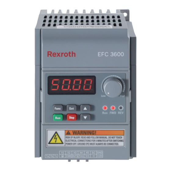
Page 52: Operating Panel
Bosch Rexroth AG EFC 3600 Operating Panel 6 Operating Panel 6.1 Figure and Description The operating panel is removable and composed of two areas: display and keys. The display shows mode settings and operation state of the frequency convert- er. The keys allow the user to program the frequency converter. -
Page 53: Led Indicator
EFC 3600 Bosch Rexroth AG Operating Panel 6.3 LED Indicator Fig. 6-3: LED indication description The LED indicator Run also blinks during dead zone time of forward and reverse rotation, period of automatic error reset and waiting time for restarting after power fault. -
Page 54: Menu Structure
Bosch Rexroth AG EFC 3600 Operating Panel 6.4 Menu Structure Fig. 6-4: Menu structure The digital operating panel can be used to toggle between menu ● options and set parameters with buttons Func, Set, ▲ and ▼. The monitoring display mode will be activated if there is no opera- ●... -
Page 55: Operating Mode
EFC 3600 Bosch Rexroth AG Operating Panel 6.5 Operating Mode Fig. 6-5: Operating mode 6.6 Operating Example Fig. 6-6: Operating example 41/259 DOK-RCON03-EFC-3600***-IT03-EN-P... -
Page 56: Commissioning
Bosch Rexroth AG EFC 3600 Commissioning 7 Commissioning 7.1 Checking and Preparation before Commissioning WARNING Ensure the plastic enclosure is in place before the device is powered on. Wait for at least 5 minutes after powering off to allow the DC capacitor being dis- charged, and do not remove the upper cover during this period. -
Page 57: Commissioning Process
Tab. 7-1: Commissioning process EFC 3600 has no internal contactor, and will be energized once ● the power supply is connected. When the Run key is pressed down (or "control by terminals" is activated), the frequency con- verter will give output. -
Page 58: Efc 3600 Basic Parameters Fast Settings
Bosch Rexroth AG EFC 3600 Commissioning 7.3 EFC 3600 Basic Parameters Fast Settings Using the operating panel to set the necessary parameters based on the applica- tion loads and specifications allows the frequency converter to start rapidly. A basic generic parameters fast setting table is given below. -
Page 59: Restore Parameters To Factory Defaults
EFC 3600 Bosch Rexroth AG Commissioning 7.4 Restore Parameters to Factory Defaults If the frequency converter fails to run the motor due to incorrect parameter set- tings, a simple solution is to initialize the parameters to factory defaults. Setting [b0.05]=1 will start initialization. -
Page 60: Parameter Settings
Bosch Rexroth AG EFC 3600 Parameter Settings 8 Parameter Settings 8.1 Group b0: System Parameters 8.1.1 Password and Access Control b0.00 User password Setting range 0 ~ 65535 Minimum unit Factory default Activate the user password protection: the default value of the password is 0 ●... - Page 61 EFC 3600 Bosch Rexroth AG Parameter Settings 0: Basic parameters. In this mode, only parameters in group b (b0 and b1) are ● visible. 1: Standard parameters. In this mode, parameters in group b and S (S0, S2 ● and S3) are visible.
-
Page 62: System Configuration
Bosch Rexroth AG EFC 3600 Parameter Settings 8.1.2 System Configuration b0.05 Parameter initialization Setting range 0 ~ 2 Minimum unit Factory default Used to restore parameters to factory defaults. A frequency converter can re- cord the recent 3 errors and the relevant variables for the last error for error di- agnosis. -
Page 63: Frequency Converter Configuration
EFC 3600 Bosch Rexroth AG Parameter Settings 8.1.3 Frequency Converter Configuration b0.20 Frequency converter rated voltage setting Setting range 200 V class: 200 ~ 240 V; 400 V class: 380 ~ 480 V Minimum unit Factory default 200 V class: 220 V; 400 V class: 380 V Used for analog output function selection "terminal output voltage". -
Page 64: Monitoring Display
Bosch Rexroth AG EFC 3600 Parameter Settings 8.1.4 Monitoring Display b0.30 Running monitoring display Setting range 0 ~ 70 Minimum unit Factory default b0.31 Stop monitoring display Setting range 0 ~ 70 Minimum unit Factory default 0: Output frequency ●... -
Page 65: Dok-Rcon03-Efc-3600***-It03-En-P
EFC 3600 Bosch Rexroth AG Parameter Settings – In this case, [d0.07] will be displayed when the frequency converter is in running monitoring mode. The setting of parameter b0.31 decides which parameter of group d will be dis- played in stop monitoring mode. -
Page 66: System Information
Bosch Rexroth AG EFC 3600 Parameter Settings [d0.15] = PID feedback x [b0.33] With: [d0.15]: PID feedback engineering value [b0.33]: PID reference / feedback coefficient Users may convert the PID engineering value to any other form they feel easy to understand via parameter b0.33. -
Page 67: Group B1: Basic Parameters
EFC 3600 Bosch Rexroth AG Parameter Settings 8.2 Group b1: Basic Parameters 8.2.1 Basic Running Control b1.00 The first frequency setting source Setting range 0 ~ 6 Minimum unit Factory default 0: Given by panel potentiometer ● Set the frequency by adjusting the potentiometer on the operating panel. - Page 68 Bosch Rexroth AG EFC 3600 Parameter Settings b1.01 Digital set frequency saving Setting range 0 ~ 3 Minimum unit Factory default Used to decide if the digital settings via ▲/▼ will be automatically saved at pow- er off or in stop mode.
- Page 69 EFC 3600 Bosch Rexroth AG Parameter Settings b1.05 Max. frequency Setting range 50.00 ~ 400.00 Hz Minimum unit 0.01 Hz Factory default 50.00 Hz b1.06 Upper frequency Setting range [b1.07] ~ [b1.05] Minimum unit 0.01 Hz Factory default 50.00 Hz b1.07...
- Page 70 Bosch Rexroth AG EFC 3600 Parameter Settings Fig. 8-1: [b1.08]=0 Fig. 8-2: [b1.08]=1 b1.10 Direction control Setting range 0 ~ 3 Minimum unit Factory default Used for general settings of direction control. It accepts all the direction control source (operating panel, communication and external terminal).
- Page 71 EFC 3600 Bosch Rexroth AG Parameter Settings This parameter is only applicable for operations by the operating panel. 0: Forward rotation ● 1: Reverse rotation ● The relationship between [b1.10] and [b1.11] is: Fig. 8-3: Relationship between [b1.10] and [b1.11] Direction control [b1.10]...
- Page 72 2: First frequency setting - second frequency setting ● EFC 3600 has two frequency setting sources: the first frequency setting source b1.00 and the second frequency setting source b1.16. It is allowed to use any or the combination of them.
-
Page 73: Acceleration/Deceleration Control
EFC 3600 Bosch Rexroth AG Parameter Settings b1.16 Second frequency setting source Setting range 0 ~ 6 Minimum unit Factory default 0: Given by panel potentiometer ● 1: Given by panel digital setting ● 2: Given by external analog input voltage (AIV) ●... - Page 74 Parameter Settings Fig. 8-5: Acceleration / Deceleration time For EFC 3600, acceleration / deceleration time is defined as the time from zero to the Max. frequency and from the Max. frequency to zero. 4 groups of acceler- ation / deceleration time are available, which can be selected by external termi- nals.
- Page 75 EFC 3600 Bosch Rexroth AG Parameter Settings Fig. 8-6: Linear mode [b1.22]=1: S-curve ● The output frequency is increased or decreased in an S-curve (the S-curve mode is used to achieve smooth start or stop) as shown in figure below.
-
Page 76: Starting Configuration
Bosch Rexroth AG EFC 3600 Parameter Settings 8.2.3 Starting configuration b1.30 Starting mode Setting range 0 ~ 2 Minimum unit Factory default b1.31 Starting frequency Setting range 0.00 ~ 50.00 Hz Minimum unit 0.01 Hz Factory default 0.05 Hz b1.32... - Page 77 EFC 3600 Bosch Rexroth AG Parameter Settings Set frequency Fig. 8-8: Start directly "Starting frequency holding time" b1.32 needs to be set as a non- zero value when the motor needs to be started with certain starting frequency. [b1.30]=1: Braking before start ●...
-
Page 78: Stopping Configuration
Bosch Rexroth AG EFC 3600 Parameter Settings The frequency converter firstly identifies the rotation speed and direction of the motor and then starts with the current frequency of the motor to realize smooth starting without shock to the rotating motor. - Page 79 EFC 3600 Bosch Rexroth AG Parameter Settings The frequency converter decelerates to stop according to the defined decel- eration time. – If an error happens due to too fast deceleration, extend the decel- eration time or calculate if additional brake resistors are required.
- Page 80 Bosch Rexroth AG EFC 3600 Parameter Settings a stop command is active, and ● [b1.40] = 0, and ● output frequency ≤ [b1.41], and ● digital input “Stopping DC-braking enabled” is active, or [b1.42] > 0. ● When [b1.42] > 0 and digital input “Stopping DC-braking enabled”...
- Page 81 EFC 3600 Bosch Rexroth AG Parameter Settings b1.44: Reserved b1.45 Overexcitation deceleration gain Setting range 1.00 ~ 1.40 Minimum unit 0.01 Factory default 1.00 b1.46 ~ b1.49: Reserved Used for the fine tuning of over excitation deceleration to obtain a better level of over excitation in V/F control mode.
-
Page 82: Group S0: V/F Control
Bosch Rexroth AG EFC 3600 Parameter Settings 8.3 Group S0: V/F Control 8.3.1 V/F Curve S0.00 V/F control mode Setting range 0 ~ 2 Minimum unit Factory default 0: Linear mode ● This mode refers to linear voltage / frequency control, which is suitable for normal constant torque loads as shown in the figure below. - Page 83 EFC 3600 Bosch Rexroth AG Parameter Settings Fig. 8-13: Square curve 2: User-defined multipoint curve ● Users can define a V/F curve with S0.01 ~ S0.06 for special loads of dewater- ing machines, centrifuges, etc. Fig. 8-14: User-defined multipoint curve...
- Page 84 Bosch Rexroth AG EFC 3600 Parameter Settings S0.01 V/F frequency 1 Setting range 0.00 Hz ~ [S0.03] Minimum unit 0.01 Hz Factory default 0.00 Hz S0.02 V/F voltage 1 Setting range 0.0 % ~ 120.0 % (of rated motor voltage) Minimum unit 0.1 %...
- Page 85 EFC 3600 Bosch Rexroth AG Parameter Settings Fig. 8-15: [S0.05] "V/F frequency 3" above [S2.00] "motor rated frequency" Fig. 8-16: [S0.05] "V/F frequency 3" below [S2.00] "motor rated frequency" In this case, the output voltage is limited to 100 % even if [S0.06] "V/F voltage 3"...
-
Page 86: Enhanced V/F Control
Bosch Rexroth AG EFC 3600 Parameter Settings 8.3.2 Enhanced V/F Control S0.20 Rated motor slip frequency Setting range 0.00 ~ 20.00 Hz Minimum unit 0.01 Hz Factory default 0.00 Hz Used to compensate the speed difference caused by the load in V/F control, and to ensure that the rotator’s speed is close to the synchronous speed with rated... - Page 87 EFC 3600 Bosch Rexroth AG Parameter Settings S0.21 Voltage boost Setting range 0.0 % ~ 20.0 % (of rated motor voltage) Minimum unit 0.1 % Factory default 5.0 % To obtain higher output torque and better stabilization, especially in low speed range, the voltage generated at the motor resistor must be taken into account.
- Page 88 Bosch Rexroth AG EFC 3600 Parameter Settings Fig. 8-20: Square V/F curve manual voltage boost For user-defined curve, the boost rule is the same with linear V/F curve. [S0.21]=0.0 %: automatic voltage boost ● Determines automatically the percentage of output voltage boost based on the output frequency and the load current.
- Page 89 EFC 3600 Bosch Rexroth AG Parameter Settings Fig. 8-22: Square V/F curve auto voltage boost S0.22 I*R boost factor Setting range 0 % ~ 320 % Minimum unit Factory default 100 % Used for further adjustment of the voltage boost. Its default value is 100 % which means no adjustment is needed.
-
Page 90: No-Trip Control
Bosch Rexroth AG EFC 3600 Parameter Settings Used to suppress the motor vibration in the case of light load or no load. In- creasing of this value will bring better effect of vibration suppression (anti hunt- ing), but too much increase will cause unstable running of the motor. Default value of 0 % means no vibration suppression. - Page 91 EFC 3600 Bosch Rexroth AG Parameter Settings Current limitation control is deactivated in any case. [S0.30]=1: OFF at constant speed. ● Current limitation control works during Acc. and Dec., but is deactivated at constant speed. [S0.30]=3: ON at constant speed.
-
Page 92: Group S2: Motor Parameters
Bosch Rexroth AG EFC 3600 Parameter Settings 8.4 Group S2: Motor Parameters 8.4.1 Motor Nameplate Parameters S2.00 Rated motor frequency Setting range 5.00 ~ 400.00 Hz Minimum unit 0.01 Hz Factory default 50.00 Hz S2.01 Rated motor rotation speed Setting range... -
Page 93: Motor Physical Data
EFC 3600 Bosch Rexroth AG Parameter Settings 8.4.2 Motor Physical Data S2.10 Stator resistance Setting range 0.00 ~ 50.00 Ω Minimum unit 0.01 Ω Factory default Depends on model S2.11 Rotator resistance Setting range 0.00 ~ 50.00 Ω Minimum unit 0.01 Ω... -
Page 94: Motor Thermal Protection
Bosch Rexroth AG EFC 3600 Parameter Settings 8.4.3 Motor Thermal Protection S2.20 Sensor type Setting range 0: PTC; 1: NTC Minimum unit Factory default S2.21 Input channel of motor temperature Setting range 0: Invalid; 1: Analog input voltage Minimum unit Factory default S2.22... - Page 95 EFC 3600 Bosch Rexroth AG Parameter Settings For a good resolution of temperature with continuous sensors (in ● general: NTCs), the value of resistor R in the figure should be close to the sensor resistance at the motor temperature limit.
-
Page 96: Group S3: Running Parameters
Bosch Rexroth AG EFC 3600 Parameter Settings 8.5 Group S3: Running Parameters 8.5.1 Jogging Parameters S3.00 Jogging frequency Setting range 0.00 Hz ~ [b1.05] Minimum unit 0.01 Hz Factory default 5.00 Hz S3.01 Jogging acceleration time Setting range 0.1 ~ 6,000.0s Minimum unit 0.1s... -
Page 97: Skip Frequency
EFC 3600 Bosch Rexroth AG Parameter Settings vated during jogging reverse / forward, the frequency converter will STOP ac- cording to the setting of “Stopping mode” [b1.40]. 8.5.2 Skip Frequency S3.05 Skip frequency 1 Setting range 0.00 Hz ~ [b1.06] Minimum unit 0.01 Hz... -
Page 98: Restarting After Power Fault
Bosch Rexroth AG EFC 3600 Parameter Settings If the set frequency is in the hysteresis range (including the boun- ● daries) of defined skip frequency, the frequency is set to upper / lower limit of skip frequency range; If the skip frequency range is set to 0.00 Hz, no skip frequency ●... -
Page 99: Brake Chopper Control
EFC 3600 Bosch Rexroth AG Parameter Settings [S3.15] = 0: the frequency converter will remain static, even if a running com- ● mand exists after power on. To start the frequency converter, please cancel and reactivate the running command. If the frequency converter was running in 3-wire control mode be- ●... -
Page 100: Additional Running Control
Bosch Rexroth AG EFC 3600 Parameter Settings 8.5.5 Additional Running Control S3.30 Forward and reverse rotation dead zone time Setting range 0.0 ~ 60.0s Minimum unit 0.1s Factory default 4.0s S3.31: Reserved S3.30 represents the waiting time when the frequency converter switches from forward / reverse rotation to reverse / forward rotation. - Page 101 EFC 3600 Bosch Rexroth AG Parameter Settings 3. Set S3.32 "UP / DOWN setting ratio" for the frequency change rate of ter- minals UP / DOWN. Fig. 8-29: External terminals Up / Down settings The combination of the control terminals are described as below:...
-
Page 102: Group E0: Input Terminal Parameters
Bosch Rexroth AG EFC 3600 Parameter Settings 8.6 Group E0: Input Terminal Parameters 8.6.1 Multi-function Digital Input Terminals E0.00 2-wire / 3-wire running control Setting range 0 ~ 2 Minimum unit Factory default In order to run the frequency converter with "2-wire / 3-wire running control", b1.02 / b1.17 needs to be set as 1. - Page 103 EFC 3600 Bosch Rexroth AG Parameter Settings Fig. 8-31: 2-wire control_2 Running status Inactive Inactive Stop Inactive Active Stop Active Inactive Forward Active Active Reverse [E0.00]=2: 3-wire control ● An additional terminal needs to be configured as "3-wire running control" and connected as below: Fig.
- Page 104 Bosch Rexroth AG EFC 3600 Parameter Settings – Preselect the direction before setting RUN command, otherwise direc- tion will change (with a possible "dead zone time"). When setting E0.00 "2-wire / 3-wire running control", 3-wire con- ● trol can only be selected after the 3-wire input terminal has been mapped.
- Page 105 EFC 3600 Bosch Rexroth AG Parameter Settings 8 multi-speeds are available with the combinations of the above 3 terminals. Fig. 8-33: Given by multi-speed Corresponding frequency Command frequency and Acc. / Dec. time parameter Multi-speed frequency 0 b1.04, E2.35 Multi-speed frequency 1 E2.10, E2.37...
- Page 106 Bosch Rexroth AG EFC 3600 Parameter Settings Acc. / Dec. time Acc. / Dec. time Selected Acc. / Dec. time terminal 2 terminal 1 Acceleration time 1 is selected (b1.20) Inactive Inactive Deceleration time 1 is selected (b1.21) Acceleration time 2 is selected (E2.00)
- Page 107 EFC 3600 Bosch Rexroth AG Parameter Settings [E2.30] Xi = 15 Simple PLC status Inactive Inactive 16: Simple PLC paused ● When the terminal is switched on, the PLC running is paused and the fre- quency converter runs at zero speed; if the terminal is switched off at this time, the frequency converter resumes the status before the PLC pause.
-
Page 108: Analog Input Channel Gain
Bosch Rexroth AG EFC 3600 Parameter Settings This function works in the same manner as the operating panel error reset function does, which allows remote error reset. "External RESET input" de- pends on the edge of the input signal (signal changes from inactive to active). -
Page 109: Analog Input Filtering Time
EFC 3600 Bosch Rexroth AG Parameter Settings 8.6.3 Analog Input Filtering Time E0.15 Analog channel filtering time Setting range 0.000 ~ 2.000s Minimum unit 0.001s Factory default 0.100s E0.16 ~ E0.19: Reserved 8.6.4 Analog Input Curve Configuration E0.20 Analog setting curve selection... - Page 110 Bosch Rexroth AG EFC 3600 Parameter Settings Setting range 0.00 Hz ~ [b1.06] Minimum unit 0.01 Hz Factory default 0.00 Hz E0.27 Curve 2 max. reference Setting range [E0.25] ~ 100.0 % Minimum unit 0.1 % Factory default 100.0 % E0.28...
- Page 111 EFC 3600 Bosch Rexroth AG Parameter Settings Fig. 8-35: Characteristics curve 1 E0.25 ~ E0.28 are used to define characteristics of curve 2. See figure below: ● Fig. 8-36: Characteristics curve 2 97/259 DOK-RCON03-EFC-3600***-IT03-EN-P...
-
Page 112: Group E1: Output Terminal Parameters
Bosch Rexroth AG EFC 3600 Parameter Settings 8.7 Group E1: Output Terminal Parameters 8.7.1 Multi-function Output Terminals E1.00 OUT1 output Setting range 0 ~ 18 Minimum unit Factory default E1.02 Relay output Setting range 0 ~ 18 Minimum unit Factory default E1.01, E1.03: Reserved... - Page 113 EFC 3600 Bosch Rexroth AG Parameter Settings Fig. 8-37: Simple PLC phase completion indication If the running time of one of the stages is so short that it finishes be- fore the “phase completion” signal of the previous stage is deactiva- ted, the signal remains active and the pulse duration calculation is restarted.
- Page 114 Bosch Rexroth AG EFC 3600 Parameter Settings See parameters E1.10 and E1.12. 13: Stopped by the external error ● This signal is activated when the error "E-St" is generated, and deactivated when the error is reset. For "E-St", see "External digital input" group.
-
Page 115: Frequency Detection
EFC 3600 Bosch Rexroth AG Parameter Settings 8.7.2 Frequency Detection E1.04 Frequency arriving at detection width Setting range 0.00 ~ 400.0 Hz Minimum unit 0.01 Hz Factory default 2.50 Hz This function is used to detect the difference between the output frequency and the set frequency. - Page 116 Bosch Rexroth AG EFC 3600 Parameter Settings Minimum unit 0.01 Hz Factory default 1.00 Hz When the output frequency exceeds the frequency set by E1.05 or E1.07, the digital output "frequency level detection signal 1 or 2 (FDT1 or FDT2)" becomes active until the output frequency is lower than the value set by (E1.05 - E1.06)
-
Page 117: Overload Pre-Warning
EFC 3600 Bosch Rexroth AG Parameter Settings 8.7.3 Overload Pre-warning E1.09 Frequency converter overload pre-warning level setting Setting range 20.0 % ~ 200.0 % (of rated frequency converter current) Minimum unit 0.1 % Factory default 110.0 % E1.10 Motor pre-warning level setting Setting range 100.0 % ~ 250.0 % (of rated motor current) -
Page 118: External Signal Counter
Bosch Rexroth AG EFC 3600 Parameter Settings 8.7.4 External Signal Counter E1.13 Middle count value Setting range 0 ~ [E1.14] Minimum unit Factory default E1.14 Target count value Setting range [E1.13] ~ 9999 Minimum unit Factory default E1.15 ~ E1.29: Reserved The corresponding digital output for "Middle / Target count value reached"... -
Page 119: Analog Output Terminal
EFC 3600 Bosch Rexroth AG Parameter Settings 8.7.5 Analog Output Terminal E1.30 FM1 analog output selection Setting range 0 ~ 7 Minimum unit Factory default E1.31 FM1 channel mode Setting range 0: 0 ~ 10 V; 1: 2 ~ 10 V... -
Page 120: Group E2: Multi-Speed And Simple Plc
Bosch Rexroth AG EFC 3600 Parameter Settings 8.8 Group E2: Multi-speed and Simple PLC 8.8.1 Acceleration/deceleration time 2, 3 and 4 E2.00 Acceleration time 2 Setting range 0.1 ~ 6,000.0s Minimum unit 0.1s Factory default 5.0s E2.01 Deceleration time 2 See E2.00 "Acceleration time 2"... - Page 121 EFC 3600 Bosch Rexroth AG Parameter Settings See parameter E2.10 "Multi-speed frequency 1" E2.17 ~ E2.29: Reserved Parameters E2.10 ~ E2.16 together with b1.04 are used to set the frequencies in multi-speed control and simple PLC. Multi-speed control ● 8 multiple speeds can be set by multi-speed control terminals, together with forward / reverse control terminals (FWD-CM and REV-CM) and acceleration / deceleration terminals.
-
Page 122: Simple Plc Basic Control
Bosch Rexroth AG EFC 3600 Parameter Settings 8.8.3 Simple PLC Basic Control E2.30 Simple PLC running mode Setting range 0 ~ 3 Minimum unit Factory default 0: Inactive. ● Simple PLC control is inactive. 1: Mode 1. ● Simple PLC stops after one cycle. In this mode, the frequency converter de- celerates to 0.00 Hz after the last stage and a STOP signal is generated. - Page 123 EFC 3600 Bosch Rexroth AG Parameter Settings Minimum unit 0.1s Factory default 20.0s E2.37 Stage 1 action selection See "Stage 0 action selection" E2.38 Stage 1 running time See "Stage 0 running time" E2.39 Stage 2 action selection See "Stage 0 action selection"...
- Page 124 Bosch Rexroth AG EFC 3600 Parameter Settings – 2: Acceleration time 2, set with parameter E2.00 – 3: Acceleration time 3, set with parameter E2.02 – 4: Acceleration time 4, set with parameter E2.04 Display 0 (right most): ● – 1: Deceleration time 1, set with parameter b1.21 –...
-
Page 125: Group E3: Pid Control
EFC 3600 Bosch Rexroth AG Parameter Settings 8.9 Group E3: PID Control 8.9.1 PID Basic Configuration PID control is a common approach used in process controls such as flow con- trol, pressure control, temperature control and other process controls. Propor-... -
Page 126: Pid Control
Bosch Rexroth AG EFC 3600 Parameter Settings E3.01 PID feedback channel Setting range 0 ~ 1 Minimum unit Factory default 0: Analog input current ● 1: Analog input voltage ● Both of them have the nature of frequency, the corresponding reference fre- quency is related to parameters E0.10 ~ E0.28. - Page 127 EFC 3600 Bosch Rexroth AG Parameter Settings – Decides the gain of deviation. – Larger P means larger scale and faster response, but too large P leads to vibration. – P cannot eliminate deviation completely. Ti: Integral time ● – Used to eliminate the deviation.
- Page 128 Bosch Rexroth AG EFC 3600 Parameter Settings change in the trend. When the output reaches its frequency limit, the integra- tion stops. 1: Continue integral regulation ● The integral value responds to the changes between reference and feedback values. When the output reaches the maximum frequency limit, the integrator continues up to its possible numerical integration limit, not the maximum fre- quency limit.
-
Page 129: E4: Error And Protection
EFC 3600 Bosch Rexroth AG Parameter Settings 8.10 E4: Error and Protection 8.10.1 Protection Configuration E4.00: Reserved E4.01 Overvoltage prevention setting Setting range 0 ~ 2 Minimum unit Factory default 0: Both disabled ● 1: Stall protection enabled, braking disabled ●... - Page 130 Bosch Rexroth AG EFC 3600 Parameter Settings Model Hysteresis voltage [V] 1P 200 V 3P 400 V When the brake chopper is controlled by the hysteresis voltage, the switching pattern is shown as below: Fig. 8-47: Switching pattern_hysteresis voltage When the duty cycle is set as 100 %, the switching will be only according to the hysteresis.
- Page 131 EFC 3600 Bosch Rexroth AG Parameter Settings Fig. 8-48: Stall overvoltage prevention level_during deceleration Excessive low settings of this parameter may not bring a successful motor deceleration. E4.03 Stall overcurrent prevention level Setting range 20.0 % ~ 250.0 % (of rated frequency converter output current) Minimum unit 0.1 %...
- Page 132 Bosch Rexroth AG EFC 3600 Parameter Settings Fig. 8-49: Stall overcurrent prevention level_during acceleration At constant speed When the output current exceeds the stall prevention level [E4.03], the fre- ● quency converter starts deceleration with the defined deceleration time. When the output current drops below [E4.03], the frequency converter accel- ●...
- Page 133 EFC 3600 Bosch Rexroth AG Parameter Settings "Low speed derating frequency" means that when the frequency is higher ● than [E4.04], the allowed continuous current is the rated current [S2.04]. When the frequency is lower than [E4.04], the allowed continuous current is linear reduced to zero speed load [S2.23] at standstill.
-
Page 134: Error Reset
Bosch Rexroth AG EFC 3600 Parameter Settings 8.10.2 Error Reset E4.15 Number of error reset attempts Setting range 0 ~ 3 Minimum unit Factory default E4.16 Interval between reset attempts Setting range 2 ~ 60s Minimum unit Factory default E4.17 ~ E4.19: Reserved... -
Page 135: System Status At The Latest Error
EFC 3600 Bosch Rexroth AG Parameter Settings 8.10.4 System Status at the Latest Error E4.30 Output frequency at latest error Display range 0.00 Hz ~ [b1.05] E4.31 Setting frequency at latest error Display range 0.00 Hz ~ [b1.05] E4.32 Output current at latest error Display range 0.0 ~ 1,000.0 A... -
Page 136: Group H0: Communication
Bosch Rexroth AG EFC 3600 Parameter Settings 8.11 Group H0: Communication H0.00 Communication protocol Setting range 0 ~ 1 Minimum unit Factory default 0: ModBus ● 1: ModBus / PROFIBUS ● It is ModBus for EFC3600-xKxx-xPx-MDA-7P-NNNN models; it is PROFIBUS for EFC3600-xKxx-xPx-PDA-7P-NNNN models. - Page 137 EFC 3600 Bosch Rexroth AG Parameter Settings H0.03 Local address Setting range ModBus: 1 ~ 247; PROFIBUS: 1 ~ 126 Minimum unit Factory default H0.04 ~ H0.07: Reserved In ModBus communication, the maximum number of frequency converters in ● the network is 247 (0 is broadcast address).
-
Page 138: Diagnosis
Monitoring parameters will be displayed on panel after a successful startup, which are parameter" decided by b0.30 and b0.31. 9.2 Diagnosis on Parameter Backup For EFC 3600, all user parameter settings can be saved as backup to and read out from the operating panel. Displayed message Diagnosis "-""--""---""----"... -
Page 139: In Run State
CPU voltage dropped to power down level, soft restart will be activated again and this message will be reset automatically. 9.4 Diagnosis on Warnings EFC 3600 has totally 4 kinds of warning messages as shown in the table below: Displayed Diagnosis... -
Page 140: Diagnosis On Errors
Diagnosis 9.5 Diagnosis on Errors 9.5.1 Error Description and Solution When EFC 3600 detects a status or situation that affects or prevents correct op- eration, an error message will be generated, as shown below: OC-1: Overcurrent at constant speed Possible reason... - Page 141 EFC 3600 Bosch Rexroth AG Diagnosis Possible reason Solution Over excitation Reduce [b1.45] Wrong motor parameter setting Correct motor parameters setting OE-1: Overvoltage at constant speed Possible reason Solution Surge voltage from power supply Check input power supply Motor to earth short circuit causes...
- Page 142 Bosch Rexroth AG EFC 3600 Diagnosis OL-1: Frequency converter overload Possible reason Solution Long time overload Reduce overload time, reduce load Excessive proportion of V/F curve Adjust V/F proportion and torque boost Motor power and frequency con- Motor power has to match with frequency converter power verter power do not match ●...
- Page 143 EFC 3600 Bosch Rexroth AG Diagnosis EEP-: Flash read/write error Possible reason Solution Try to backup the data with the operating panel, and then con- Flash memory in a bad condition tact with service SPI-: SPI communication problem Possible reason...
- Page 144 Bosch Rexroth AG EFC 3600 Diagnosis Ot: Motor over temperature Possible reason Solution ● Check load Excessive load or bad cooling ● Provide a better cooling condition Temperature sensor defect Check the motor temperature feedback signal Different motor with different maximum temperature, configure Wrong protection level external division circuit and set the protection level (S2.22)
- Page 145 EFC 3600 Bosch Rexroth AG Diagnosis OH: Frequency converter over temperature Possible reason Solution ● Reduce ambient temperature, improve ventilation and heat dissipation; clear dust, cotton wadding in air ducts; Frequency converter (heat sink) tem- check fan and its power supply connection (if available) perature is higher than max.
- Page 146 Bosch Rexroth AG EFC 3600 Diagnosis FFE-: Firmware does not match Possible reason Solution Operating panel may be placed to the frequency converter with older/ Contact with service newer firmware I/O board may be removed to another device Contact with service...
- Page 147 EFC 3600 Bosch Rexroth AG Diagnosis UE-1: Undervoltage during running Possible reason Solution Power failure during running Check input power supply Main circuit capacitor deterioration Contact with service UH: Frequency converter under temperature Possible reason Solution Provide a reasonable ambient temperature that Ambient temperature is lower than -15 °C...
- Page 148 Bosch Rexroth AG EFC 3600 Diagnosis CE8-: Communication problem on I/O board (No communication frames re- ceived) Possible reason Solution EMC problem Remove the environmental interference or EMI Defect on I/O board Replace the I/O board or contact with service...
- Page 149 EFC 3600 Bosch Rexroth AG Diagnosis CE9-: Firmware version error Possible reason Solution Firmware version of I/O board does not Contact with service match with others in the system OE-4: Overvoltage during stop Possible reason Solution ● Increase deceleration time Excessive inertia on the load ●...
-
Page 150: Error Reactions Of The Frequency Converter
Bosch Rexroth AG EFC 3600 Diagnosis 9.5.2 Error Reactions of the Frequency Converter If an error happens in running state, the frequency converter has to perform a suitable error reaction. For general errors, the frequency converter will free- wheel to stop. Some errors may be associated with special error reaction (e.g. -
Page 151: Technical Data
EFC 3600 Bosch Rexroth AG Technical Data 10 Technical Data 10.1 General Technical Data Input 1 AC 200 ~ 240 V (-10 % / +10 %) (TN-Net) Power supply voltage 3 AC 380 ~ 480 V (-15 % / +10 %) (TN-Net) Power supply frequency 50 ~ 60 Hz (±5 %) - Page 152 Bosch Rexroth AG EFC 3600 Technical Data Automatic PWM frequency adaptation, main and auxiliary refer- ence, slip compensation, torque boost, automatic voltage stabili- zation selection, DC brake, restarting after power fault immedi- Main control functions ately, intelligent fan control, 2-wire / 3-wire control, quick start- up, parameter copy, PID control, multi-speed control, no-trip control, etc.
-
Page 153: Electrical Data
0K40 means 0.4 kW. ● 10.3 Derating of Electrical Data 10.3.1 Derating and Ambient Temperature The ambient temperature for EFC 3600 is -10 ~ 50 ℃. If the ambient temperature is within this range, there will be no need for de- ● rating. -
Page 154: Derating And Mains Voltage
1 % power derating every 2 V decreasing when mains voltage < 200 V. 10.3.3 Derating and Output Current For the whole power range of EFC 3600 from 0K40 to 4K00, current derating based on pulse frequency is unnecessary. 140/259... -
Page 155: Electromagnetic Compatibility (Emc)
EFC 3600 Bosch Rexroth AG Electromagnetic Compatibility (EMC) 11 Electromagnetic Compatibility (EMC) 11.1 EMC Requirements 11.1.1 General Information The electromagnetic compatibility (EMC) or electromagnetic interference (EMI) includes the following requirements: Sufficient noise immunity of an electric installation or an electric device ●... - Page 156 Bosch Rexroth AG EFC 3600 Electromagnetic Compatibility (EMC) Minimum immunity requirements for PDSs intended for use in the second envi- ronment Basic standard Performance Port Phenomenon for test Level (acceptance method criterion) 4 kV CD or 8 kV AD IEC 61000-4-2...
- Page 157 EFC 3600 Bosch Rexroth AG Electromagnetic Compatibility (EMC) Minimum immunity requirements for PDSs intended for use in the first environ- ment Basic standard Performance Port Phenomenon for test Level (acceptance method criterion) 4 kV CD or 8 kV AD IEC 61000-4-2...
-
Page 158: Noise Emission Of The Drive System
Bosch Rexroth AG EFC 3600 Electromagnetic Compatibility (EMC) Evaluation criterion Evaluation criterion Explanation (abbreviated form from EN 61800-3) Deviations within allowed range Automatic recovery after interference Switched off without automatic recovery. Device remains undamaged Tab. 11-3: Evaluation criterion 11.1.3 Noise Emission of the Drive System... - Page 159 EFC 3600 Bosch Rexroth AG Electromagnetic Compatibility (EMC) Curves of limit IEC / EN In this CISPR 11 Explanation value 61800-3 document characteristic One of the following 3 requirements must have been fulfilled: Mains connection current>400 A, ● IT mains or required dynamic drive...
- Page 160 Bosch Rexroth AG EFC 3600 Electromagnetic Compatibility (EMC) 1.1 C3 2 3.2 C2 1 environment, QP, I>100 A (class environment, AV (1 environment, A, group 2, I>100 A) even if source of interference in 2 1.2 C3 2 environment, AV, I>100 A (class A, environment) (class A, group 1) group 2, I>100 A)
- Page 161 EN 61800-3 has to be observed. According to IEC 61800-3, components of EFC 3600 drive system are products of category C3: with internal EMC filter ●...
-
Page 162: Ensuring The Emc Requirements
EFC 3600 with an external EMC filter. Minimum immunity requirements in the second environment according to ● product standard EN 61800-3 have been complied with for EFC 3600 with in- ternal and external EMC filters. Applicability for End Product Measurements of the drive system with an arrangement typical for the system are not in all cases applicable to the status in a machine or installation. -
Page 163: Emc Measures For Design And Installation
Case 1: Delivery of the drive system. ● According to the regulations, EFC 3600 drive system is complied with product standard EN 61800-3 C3 (with internal EMC filters) or EN 61800-3 C1 (with external EMC filters). The drive system is listed in the declaration of EMC conformity. - Page 164 Bosch Rexroth AG EFC 3600 Electromagnetic Compatibility (EMC) Control Cabinet Grounding Connect all metal parts of the cabinet with one another over the largest possi- ble surface area to establish a good electrical connection. This, too applies to the mounting of the external mains filter. If required, use serrated washers which cut through the paint surface.
-
Page 165: Emc-Optimal Installation In Facility And Control Cabinet
EFC 3600 Bosch Rexroth AG Electromagnetic Compatibility (EMC) Digital Signal Lines Ground the shields of digital signal lines at both ends (transmitter and receiver) over the largest possible surface area and with low impedance. This avoids low frequency interference current (in the mains frequency range) on the shield. - Page 166 Bosch Rexroth AG EFC 3600 Electromagnetic Compatibility (EMC) Division into Areas (zones) Exemplary arrangements in the control cabinet: See fig. 11-3 "Control cabinet mounting according to interference areas – exemplary arrangements" on page 153. We distinguish three areas: 1. Interference-free area of control cabinet (area A):...
-
Page 167: Control Cabinet Mounting According To Interference Areas - Exem- Plary Arrangements
EFC 3600 Bosch Rexroth AG Electromagnetic Compatibility (EMC) 11.3.3 Control Cabinet Mounting according to Interference Areas – Ex- emplary Arrangements Fig. 11-3: Control cabinet mounting according to interference areas – exemplary arrange- ments 153/259 DOK-RCON03-EFC-3600***-IT03-EN-P... -
Page 168: Design And Installation In Area A - Interference-Free Area Of Control Cabinet
Bosch Rexroth AG EFC 3600 Electromagnetic Compatibility (EMC) 11.3.4 Design and Installation in Area A – Interference-free Area of Con- trol Cabinet Arrangement of the Components in the Control Cabinet Comply with a distance of at least 200 mm (distance d1 in the figure): Between components and electrical elements (switches, pushbuttons, fuses, ●... - Page 169 EFC 3600 Bosch Rexroth AG Electromagnetic Compatibility (EMC) Routing and Connecting a Neutral Conductor (N) If a neutral conductor is used together with a three-phase connection, it must not be installed unfiltered in areas B and C, in order to keep interference off the mains.
-
Page 170: Design And Installation In Area B - Interference-Susceptible Area Of Control Cabinet
Bosch Rexroth AG EFC 3600 Electromagnetic Compatibility (EMC) See also "Division into Areas (zones)" on page 0 Point of Connection for Environment Grounding Conductor at Machine, Installa- tion, Control Cabinet The equipment grounding conductor of the power cable of the machine, installa-... -
Page 171: Ground Connections
EFC 3600 Bosch Rexroth AG Electromagnetic Compatibility (EMC) Influence of the Motor Power Cable The longer the motor cable, the greater its leakage capacitors. To comply with a certain EMC limit value, the allowed leakage capacitance of he mains filter is limited. -
Page 172: Installing Signal Lines And Signal Cables
Bosch Rexroth AG EFC 3600 Electromagnetic Compatibility (EMC) tion points, remove the lacquer so that there is safe electrical contact over a large surface area. You achieve contact over a large surface area by means of bare connection surfaces or several connection screws. For screw connections, you can establish the contact to lacquered surfaces by using tooth lock wash- ers. -
Page 173: General Measures Of Radio Interference Suppression For Relays, Contactors, Switches, Chokes And Inductive Loads
EFC 3600 Bosch Rexroth AG Electromagnetic Compatibility (EMC) Connect the shield of analog signal lines at one end over a large surface area, normally in the control cabinet at the analog device. Make sure the connection to ground/housing is short and over a large surface area. -
Page 174: Accessories
Bosch Rexroth AG EFC 3600 Accessories 12 Accessories 12.1 Mains Choke 12.1.1 Mains Choke Selection EFC 3600 model Mains choke type 0K40-1P2 FENL01.1E-2100-N0010-N-240 0K75-1P2 1K50-1P2 FENL01.1E-0700-N0030-N-240 2K20-1P2 0K40-3P4 FENL01.1E-2800-N0005-N-480 0K75-3P4 1K50-3P4 FENL01.1E-2000-N0007-N-480 2K20-3P4 FENL01.1E-1400-N0010-N-480 4K00-3P4 FENL01.1E-0930-N0015-N-480 Tab. 12-1: Mains choke selection 12.1.2 Dimensions... - Page 175 EFC 3600 Bosch Rexroth AG Accessories Fig. 12-2: FENL01.1E-0700-N0030-N-240 161/259 DOK-RCON03-EFC-3600***-IT03-EN-P...
- Page 176 Bosch Rexroth AG EFC 3600 Accessories Fig. 12-3: FENL01.1E-(2800-N0005/2000-N0007/1400-N0010)-N-480 162/259 DOK-RCON03-EFC-3600***-IT03-EN-P...
- Page 177 EFC 3600 Bosch Rexroth AG Accessories Fig. 12-4: FENL01.1E-0930-N0015-N-480 163/259 DOK-RCON03-EFC-3600***-IT03-EN-P...
-
Page 178: Electrical Data
Bosch Rexroth AG EFC 3600 Accessories 12.1.3 Electrical data 2100- 0700- 2800- 2000- 1400- 0930- Description N0010 N0030 N0005 N0007 N0010 N0015 Rated voltage AC 200 V /50 Hz AC 380 V /50 Hz Rated current [A] Rated inductance [mH] 0.93... -
Page 179: Emc Filter
Bosch Rexroth AG Accessories 12.2 EMC Filter 12.2.1 The Function of EMC Filter EMC filters are used to reduce radio interference and mains pollution. 12.2.2 External EMC Filter Type EFC 3600 model External EMC filter type 0K40-1P2 E0006-A-240 0K75-1P2 E0010-A-240... - Page 180 Bosch Rexroth AG EFC 3600 Accessories Fig. 12-5: E0006-A-240 166/259 DOK-RCON03-EFC-3600***-IT03-EN-P...
- Page 181 EFC 3600 Bosch Rexroth AG Accessories Fig. 12-6: E0010-A-240 167/259 DOK-RCON03-EFC-3600***-IT03-EN-P...
- Page 182 Bosch Rexroth AG EFC 3600 Accessories Fig. 12-7: E0020-A-240_E0025-A-240 168/259 DOK-RCON03-EFC-3600***-IT03-EN-P...
- Page 183 EFC 3600 Bosch Rexroth AG Accessories Fig. 12-8: E0008-A-480 Fig. 12-9: E0020-A-480 169/259 DOK-RCON03-EFC-3600***-IT03-EN-P...
- Page 184 Bosch Rexroth AG EFC 3600 Accessories Electrical data Using EMC filters in mains grounded via outer conductor. When using EMC filters in mains grounded via outer conductor, use an isolating transformer between mains and EMC filter. Description Degree of protection ac- –...
-
Page 185: Brake Resistor
EFC 3600 Bosch Rexroth AG Accessories 12.3 Brake Resistor 12.3.1 Brief Introduction Energy regenerated when a 3-phase AC motor is decelerated (the frequency is reduced) is recovered and fed into the frequency converter. To prevent over voltage of the frequency converter, an external brake resistor may be used. A power transistor discharges the DC bus voltage energy (braking voltage thresh- old at approx. - Page 186 Bosch Rexroth AG EFC 3600 Accessories EFC 3600 Brake Brake resistor frequency converter chopper Model Type- Typecode Qty. Typecode Parameter Qty. code [kW] 0K40-1P2 Internal – 0060-N400R-D 400 Ω/60 W 0.75 0K75-1P2 Internal – 0100-N190R-D 190 Ω/100 W 1K50-1P2 Internal –...
- Page 187 EFC 3600 Bosch Rexroth AG Accessories In the tables, the recommended resistance of the brake resistor is ● 100 % braking torque, selected according to necessity. If the ac- tually needed torque is not 100 %, the resistance of the brake re- sistor in the table should be adjusted in inverse proportion, i.e.
-
Page 188: Brake Resistor In Aluminum Housing
Bosch Rexroth AG EFC 3600 Accessories 12.3.3 Brake Resistor in Aluminum Housing Fig. 12-11: Brake resistor in aluminum housing 174/259 DOK-RCON03-EFC-3600***-IT03-EN-P... - Page 189 EFC 3600 Bosch Rexroth AG Accessories Dimensions [mm] 0500-N065R-D – 1.5 M6 1.03 0500-N180R-D – 1.5 M6 1.03 0500-N330R-D – 1.5 M6 1.03 0400-N095R-D – 1.5 M6 0400-N500R-D – 1.5 M6 0300-N065R-D – 1.5 M6 0.62 0300-N330R-D – 1.5 M6 0.62...
-
Page 190: Motor Choke
Bosch Rexroth AG EFC 3600 Accessories 12.4 Motor Choke 12.4.1 Motor Choke Selection EFC 3600 model Motor choke type 0K40-1P2 0K40-3P4 FEML01.1E-1400-N0005-N-480 0K75-3P4 0K75-1P2 FEML01.1E-1000-N0007-N-480 1K50-3P4 1K50-1P2 FEML01.1E-0700-N0010-N-480 2K20-3P4 2K20-1P2 FEML01.1E-0470-N0015-N-480 4K00-3P4 Tab. 12-8: Motor choke selection 176/259 DOK-RCON03-EFC-3600***-IT03-EN-P... -
Page 191: Dimensions
EFC 3600 Bosch Rexroth AG Accessories 12.4.2 Dimensions Fig. 12-12: FEML01.1E-(1400-N0005/1000-N0007/0700-N0010)-N-480 177/259 DOK-RCON03-EFC-3600***-IT03-EN-P... - Page 192 Bosch Rexroth AG EFC 3600 Accessories Fig. 12-13: FEML01.1E-0470-N0015-N-480 178/259 DOK-RCON03-EFC-3600***-IT03-EN-P...
-
Page 193: Electrical Data
EFC 3600 Bosch Rexroth AG Accessories 12.4.3 Electrical data Description 1400-N0005 1000-N0007 0700-N0010 0470-N0015 Rated voltage AC 380 V /50 Hz Rated current [A] Rated inductance [mH] 0.47 Dielectric strength 3,000 V / 5 mA / 10s Insulation resistance ≥ 100 MΩ... - Page 194 Bosch Rexroth AG EFC 3600 Accessories Recommended opening dimensions at control cabinet Fig. 12-14: Recommended opening dimensions at control cabinet Mounting the plate and the operating panel Step 1: Push the mounting plate into the opening in the direction perpendicular to the control cabinet, the back view is as below.
- Page 195 EFC 3600 Bosch Rexroth AG Accessories Fig. 12-16: Fix the mounting plate Step 3: Push the operating panel in the direction perpendicular to the mounting plate, the front view is as below. Fig. 12-17: Mount the operating panel Step 4: Connect the operating panel to the frequency converter with the con- nection cable and fix the cable connector on the mounting plate with 2 M3x10 screws.
-
Page 196: Operating Panel Cable For Control Cabinet Mounting
Bosch Rexroth AG EFC 3600 Accessories Fig. 12-18: Connect and fix the cable 12.6.2 Operating Panel Cable for Control Cabinet Mounting The cable FRKS0005/001,0, which is 1 m long (see chapter 17.3 "Appendix 3: Type Coding" on page 242), is used to connect the operating panel for control cabinet mounting with the frequency converter. - Page 197 EFC 3600 Bosch Rexroth AG Accessories Dimensions and connection figure Fig. 12-19: Shielded cable connection with accessories 183/259 DOK-RCON03-EFC-3600***-IT03-EN-P...
-
Page 198: Communication Protocols
EFC 3600 Communication Protocols 13 Communication Protocols 13.1 Brief Introduction EFC 3600 frequency converters provide standard RS485 communication port to realize the communication between the master and slaves via ModBus or ① PROFIBUS protocol. With the help of a PC, a PLC or an external computer a "single master/multiple slaves"... - Page 199 EFC 3600 Bosch Rexroth AG Communication Protocols Transmission The transmission is of RTU (Remote Terminal Unit) mode with frames containing no message header or end mark. A typical RTU frame format is shown below: Slave address Function code Data 1 byte...
-
Page 200: Modbus Interface
Bosch Rexroth AG EFC 3600 Communication Protocols 13.2.2 ModBus Interface ModBus RJ11 communication interface for MDA models Fig. 13-1: ModBus RJ11 communication interface ModBus DB9 communication interface for PDA models Fig. 13-2: ModBus DB9 communication interface Signal Signal Signal Not used... -
Page 201: Modbus Function And Message Format
Supported functions The main function of ModBus is to read and to write parameters. Different func- tion codes decide different operation requests. ModBus functions managed by EFC 3600 and their limits are shown in the table below: Code Function name Broadcast Max. - Page 202 Bosch Rexroth AG EFC 3600 Communication Protocols Number Number Last word Address of 1 word val- CRC16 Slave of bytes value word 0x10 of words – Hi | Lo Hi | Lo Hi | Lo Hi | Lo Lo | Hi Tab.
- Page 203 EFC 3600 Bosch Rexroth AG Communication Protocols Function example Function 0x03: Read N register words, range: 1 ~ 16 Example: It is necessary to read 2 continuous words starting from communica- tion register 0100H of the slave frequency converter addressed at 01H. The frame structure is described in the tables below.
- Page 204 Bosch Rexroth AG EFC 3600 Communication Protocols Function 0x06: Write one register word Frequent writing may damage the internal regis- CAUTION ters! When data is written into the internal registers, there is a limit on the writing ● times. The register address may be damaged once the writing times is beyond the writing limit.
- Page 205 EFC 3600 Bosch Rexroth AG Communication Protocols Function 0x08: Diagnostics Example: To test the communication loop of 2 continuous words 1234H and 5678H with frequency converter slave address 01H, the frame structure is de- scribed in the tables below: Message start Transmission time for 3.5 bytes...
- Page 206 Bosch Rexroth AG EFC 3600 Communication Protocols Function 0x10: Write N register words, range 1 ~ 16 Example: To modify 2 continuous registers start from 0114H with words 0032H and 0032H with slave frequency converter address 01H. The frame structure is...
- Page 207 EFC 3600 Bosch Rexroth AG Communication Protocols Message start Transmission time for 3.5 bytes Slave address ModBus function code Higher byte of read register start address Lower byte of read register start address Higher byte of read register number Lower byte of read register number...
- Page 208 Error code Exception code CRC16 Lo | Hi Exception codes for EFC 3600 frequency converters: 1=Parameter cannot be modify owing to user password locked ● 2=The function requested is not recognized by the slave, i.e. not equal to 3, 6, ●...
-
Page 209: Communication Mapping Register Address Distribution
To read out the module temperature (d0.16) of EFC 3600 frequency converter, use register address 0x0D10 (0x0D = Group d0, index 0x10=16). To set V/f curve mode (S0.00) of EFC 3600 frequency converter, use register ad- dress 0x0200 (0x02 = Group S0, index 0). - Page 210 Bosch Rexroth AG EFC 3600 Communication Protocols Communication control registers The address of command word register for communication control is 0x4000. This register is write-only. The frequency converter is controlled through writing data into the address. The definition of each bit is shown in table below:...
- Page 211 EFC 3600 Bosch Rexroth AG Communication Protocols Communication state feedback registers (0x5000) The frequency converter state can be monitored by reading the register. This register is read-only. The definition of each bit is shown in the table below: Value Description 15 ~ 8 –...
-
Page 212: Modbus Communication Example
Bosch Rexroth AG EFC 3600 Communication Protocols 13.2.5 ModBus Communication Example One slave address is 01H. The frequency setting of the frequency converter has been set to "Given by communication" and the RUN command source is set to "Inputting commands by communication". It is required for the motor connected to the frequency converter to run with 50 Hz (forward rotation). -
Page 213: Special Notes
EFC 3600 Bosch Rexroth AG Communication Protocols 13.2.6 Special Notes 1. The external computer can not write to function codes b0.06 "Parameter replication", b0.30 "running monitoring display" and b0.31 "Stop monitor- ing display". 2. b0.00 "User password" and b0.05 "Parameter initialization" do not support multiple write including single write in multiple write;... - Page 214 Bosch Rexroth AG EFC 3600 Communication Protocols Recommendations on networking Use shielded twisted pair cable to connect RS485 links. ● ModBus cable should be adequately away from power cables (30 cm in mini- ● mum). Avoid crossing of ModBus cables and power cables and use orthogonal cross- ●...
-
Page 215: Profibus Protocol
PROFIBUS-FMS (Fieldbus Message Specifications), PROFIBUS-DP (Distributed Peripheral Equipment) and PROFIBUS-PA (Process Automation). EFC 3600 PDA models support PROFIBUS-DP Protocol. PROFIBUS is widely used in various industries such as manufacturing automa- tion and process automation, building, transportation, electric power, etc. -
Page 216: Profibus Interface
Bosch Rexroth AG EFC 3600 Communication Protocols 13.3.3 PROFIBUS Interface Fig. 13-4: PROFIBUS DB9 interface Terminal sign Terminal name Function description – Reserved – Reserved PROFIBUS_B PROFIBUS terminal_B PROFIBUS data cable B Request for signal sending – Power- – Power+ –... -
Page 217: Relationship Between Communication Rate And Cables
PPO data type PROFIBUS-DP defines data structure for periodical data communication as PPO (the Parameter Process date Object). EFC 3600 PDA models support 5 PPO types shown in figure below. PPO message is divided into two data areas in terms of transmission data contents: Parameter area (PKW area): read or write a parameter of a of slave. - Page 218 Bosch Rexroth AG EFC 3600 Communication Protocols Fig. 13-5: PPO type PKW parameter area PKW parameter area description This data area is composed of ID, IND, VALUE_high and VALUE_low, as shown in figure below. They are used to read or modify the parameter of a parameter of a frequency converter, but only one parameter can be read or modified each time.
- Page 219 EFC 3600 Bosch Rexroth AG Communication Protocols Request data frame in PKW area Word Identifier Value Description 15 ~ 8 Reserved No request 7 ~ 0 Read Write 15 ~ 8 Group No. for parameter Index No. of function code within the...
- Page 220 Bosch Rexroth AG EFC 3600 Communication Protocols Error message after execution failure in PKW area Error code Meaning Reason Password locked User password is locked Invalid command code Command codes (bit15 to 12 of ID) are not 0, 1 or 2.
- Page 221 EFC 3600 Bosch Rexroth AG Communication Protocols Example 2 Modifying value of parameter b1.20 'Acceleration time 1'. 0x01 is the parameter group, 0x14 is the index No. of the function code within the parameter group. If the modifying value is 0x0064, then request and response data frames in PKW...
- Page 222 Bosch Rexroth AG EFC 3600 Communication Protocols Examples for operation of PZD process data area Example 1 The master communicates with the slave via PPO4. We need set monitoring pa- rameters corresponding to PZD3 - PZD6, see fig. 13-5 "PPO type" on page 204.
- Page 223 EFC 3600 Bosch Rexroth AG Communication Protocols Communication parameter configuration Communication related parameter settings Parameter Name Setting range of parameter b1.00 First frequency setting source 5: Set by communication b1.02 First RUN command source 2: Set control commands by communication b1.16...
- Page 224 Bosch Rexroth AG EFC 3600 Communication Protocols Parameter configuration of master For master related parameter configuration, refer to descriptions for master. The address configured for slave in the master should be consistent with the pa- rameter address configured for the slave. Communication baud rate and PPO type are determined by the master.
-
Page 225: Maintenance
EFC 3600 Bosch Rexroth AG Maintenance 14 Maintenance 14.1 Safety Instructions High electric voltage! Risk of death or severe WARNING bodily injury by electric shock! Only those trained and qualified to work with or on electrical equipment are ● permitted to operate, maintain and repair this equipment. -
Page 226: Periodic Inspection
Bosch Rexroth AG EFC 3600 Maintenance 14.3 Periodic Inspection In addition to daily inspection, periodic inspection of frequency converters is al- so necessary. The inspection cycle should be less than 6 months. For operation details, please see table below: Inspection... -
Page 227: Operating Panel Removal And Mounting
EFC 3600 Bosch Rexroth AG Maintenance 14.4 Operating Panel Removal and Mounting Fig. 14-1: Operating panel removal 213/259 DOK-RCON03-EFC-3600***-IT03-EN-P... - Page 228 Bosch Rexroth AG EFC 3600 Maintenance Fig. 14-2: Operating panel mounting 214/259 DOK-RCON03-EFC-3600***-IT03-EN-P...
-
Page 229: Fan Removal And Mounting
EFC 3600 Bosch Rexroth AG Maintenance 14.5 Fan Removal and Mounting Fig. 14-3: Fan removal 215/259 DOK-RCON03-EFC-3600***-IT03-EN-P... - Page 230 Bosch Rexroth AG EFC 3600 Maintenance Fig. 14-4: Fan mounting 216/259 DOK-RCON03-EFC-3600***-IT03-EN-P...
-
Page 231: Service And Support
EFC 3600 Bosch Rexroth AG Service and Support 15 Service and Support Our worldwide service network provides an optimized and efficient support. Our experts offer you advice and assistance should you have any queries. You can contact us 24/7. Service Germany Our technology-oriented Competence Center in Lohr, Germany, is responsible for all your service-related queries for electric drive and controls. -
Page 232: Environmental Protection And Disposal
Bosch Rexroth AG EFC 3600 Environmental Protection and Disposal 16 Environmental Protection and Disposal 16.1 Environmental Protection Production Processes The products are made with energy- and resource-optimized production pro- cesses which allow re-using and recycling the resulting waste. We regularly try to replace pollutant-loaded raw materials and supplies by more environment- friendly alternatives. - Page 233 Used batteries can contain hazardous substances, which can harm the environ- ment or the people´s health when they are improper stored or disposed of. After use, the batteries or accumulators contained in Rexroth products have to be properly disposed of according to the country-specific collection.
-
Page 234: Appendix
Bosch Rexroth AG EFC 3600 Appendix 17 Appendix 17.1 Appendix 1: Abbreviations Rexroth EFC 3600 Frequency Converter drive system is composed of individual parts (components) for application in different circumstances. EFC 3600: EFC 3600 frequency converter ● FPCC: Operating panel ●... -
Page 235: Group B0: System Parameters
EFC 3600 Bosch Rexroth AG Appendix 17.2.2 Group b0: System Parameters Password and access control Code Name Setting range Min. unit Default Attri. b0.00 User password 0 ~ 65535 RUN/STOP Manufacturer b0.01 0 ~ 65535 STOP password 0: Basic parameters 1: Standard parameters b0.02 Access authority setting... - Page 236 Bosch Rexroth AG EFC 3600 Appendix Frequency converter configuration Code Name Setting range Min. unit Default Attri. 200 V: 200 ~ 240 V 220 V Rated frequency convert- b0.20 STOP er voltage setting 400 V: 380 ~ 480 V 380 V b0.21 Carrier frequency...
-
Page 237: Group B1: Basic Parameters
EFC 3600 Bosch Rexroth AG Appendix 17: Firmware version 1 18: Firmware version 2 19: Firmware version 3 20: Actual carrier frequency 70: High resolution output current System information Code Name Setting range Min. unit Default Attri. b0.40 Cumulative running time... - Page 238 Bosch Rexroth AG EFC 3600 Appendix Code Name Setting range Min. unit Default Attri. Second command b1.17 0 ~ 2 STOP source b1.03, b1.12 ~ b1.14, b1.18 ~ b1.19 Reserved Setting range of b1.00 and b1.16: 0: Given by panel potentiometer...
- Page 239 EFC 3600 Bosch Rexroth AG Appendix Starting configuration Code Name Setting range Min. unit Default Attri. 0: Start directly b1.30 Starting mode 1: Braking before start STOP 2: Start with speed capture b1.31 Starting frequency 0.00 ~ 50.00 Hz 0.01 Hz 0.05 Hz...
-
Page 240: Group S0: V/F Control
Bosch Rexroth AG EFC 3600 Appendix 17.2.4 Group S0: V/F control V/F curve Code Name Setting range Min. unit Default Attri. 0: Linear mode S0.00 V/F curve mode 1: Square curve STOP 2: User-defined multipoint curve S0.01 V/F frequency 1 0.00 Hz ~ [S0.03]... -
Page 241: Group S2: Motor Parameters
EFC 3600 Bosch Rexroth AG Appendix No-trip control Code Name Setting range Min. unit Default Attri. 0: OFF S0.30 Current limitation control 1: OFF at constant speed STOP 3: ON at constant speed Automatic current limitation 20 % ~ 250 % (of rated fre- S0.31... -
Page 242: Group S3: Running Parameters
Bosch Rexroth AG EFC 3600 Appendix Motor physical data Code Name Setting range Min. unit Default Attri. S2.10 Stator resistance 0.00 ~ 50.00 Ω 0.01 Ω STOP S2.11 Rotator resistance Depends S2.12 Leakage inductance 0.00 ~ 200.00 mH 0.01 mH... - Page 243 EFC 3600 Bosch Rexroth AG Appendix Skip frequency Code Name Setting range Min. unit Default Attri. S3.05 Skip frequency 1 0.00 Hz ~ [b1.06] 0.01 Hz 0.00 Hz STOP S3.06 Skip frequency 2 0.00 Hz ~ [b1.06] 0.01 Hz 0.00 Hz STOP S3.07 Skip frequency 3...
-
Page 244: Group E0: Input Terminals
Bosch Rexroth AG EFC 3600 Appendix 17.2.7 Group E0: Input Terminals Multi-function digital input terminals Code Name Setting range Min. unit Default Attri. 0: Forward/stop, reverse/stop E0.00 2-wire/3-wire running control 1: Forward/reverse, run/stop STOP 2: 3-wire control E0.01 Terminal X1 STOP E0.02 Terminal X2... - Page 245 EFC 3600 Bosch Rexroth AG Appendix Analog input channel gain Code Name Setting range Min. unit Default Attri. Analog input voltage (AIV) channel gain E0.10 0.00 ~ 10.00 0.01 1.00 RUN/STOP Analog input current (AIC) channel gain E0.12 0.00 ~ 10.00 0.01...
-
Page 246: Group E1: Output Terminals
Bosch Rexroth AG EFC 3600 Appendix 17.2.8 Group E1: Output Terminals Multi-function output terminals Code Name Setting range Min. unit Default Attri. E1.00 OUT1 output 0: Frequency converter ready for running 1: Frequency converter is running 2: DC braking indication... - Page 247 EFC 3600 Bosch Rexroth AG Appendix Overload pre-warning Code Name Setting range Min. unit Default Attri. 20.0 % ~ 200.0 % (of rated Frequency converter over- E1.09 frequency converter cur- 0.1 % 110.0 % STOP load pre-warning level setting rent) 100.0 % ~ 250.0 %...
-
Page 248: Group E2: Multi-Speed And Simple Plc
Bosch Rexroth AG EFC 3600 Appendix 17.2.9 Group E2: Multi-speed and Simple PLC Acceleration/deceleration time 2, 3 and 4 Code Name Setting range Min. unit Default Attri. E2.00 Acceleration time 2 0.1s 10.0s RUN/STOP E2.01 Deceleration time 2 0.1s 10.0s RUN/STOP E2.02 Acceleration time 3... - Page 249 EFC 3600 Bosch Rexroth AG Appendix PLC stage control Code Name Setting range Min. unit Default Attri. E2.35 Stage 0 action selection STOP E2.37 Stage 1 action selection STOP 011, 012, 013, 014, 021, E2.39 Stage 2 action selection 022, 023, 024, 031, 032,...
-
Page 250: Group E3: Pid Control
Bosch Rexroth AG EFC 3600 Appendix 17.2.10 Group E3: PID Control PID basic configuration Code Name Setting range Min. unit Default Attri. 0: No PID control 1: Panel potentiometer 2: Panel digital setting 3: Analog input voltage (AIV) E3.00 PID reference channel... -
Page 251: Group E4: Error And Protection
EFC 3600 Bosch Rexroth AG Appendix 17.2.11 Group E4: Error and Protection Protection configuration Code Name Setting range Min. unit Default Attri. E4.01 Overvoltage prevention setting 0 ~ 2 STOP 200V class: 300 ~ 390 V 390 V Stall overvoltage prevention E4.02... - Page 252 Bosch Rexroth AG EFC 3600 Appendix Error code memory Code Name Setting range Min. unit Default Attri. E4.20 Last error type read only E4.21 Second last error type 0 ~ 51 read only E4.22 Third last error type read only E4.23 ~ E4.29...
- Page 253 EFC 3600 Bosch Rexroth AG Appendix 28: PSr-, problem with power supply on the main board 31: ESS-, soft start error 32: CE5-, internal problem on main board 33: UE-1, undervoltage during run 34: UH, frequency converter under temperature 35: FHE-, manufacturer parameter defect or mismatch to hardware...
-
Page 254: Group H0: Communication
Bosch Rexroth AG EFC 3600 Appendix 17.2.12 Group H0: Communication General communication configuration Code Name Setting range Min. unit Default Attri. 0: ModBus H0.00 Communication protocol STOP 1: ModBus / PROFIBUS ① 0: 1200 bps 1: 2400 bps 2: 4800 bps H0.01 Baud rate... -
Page 255: Group D: Monitoring Parameters
EFC 3600 Bosch Rexroth AG Appendix 17.2.13 Group d: Monitoring Parameters Monitoring parameters Code Name Setting range Min. unit Default Attri. d0.00 Output frequency 0.00 ~ 400.00 Hz 0.01 Hz 0.00 Hz read only d0.01 Output velocity 0 ~ 65535 rps... -
Page 256: Appendix 3: Type Coding
Bosch Rexroth AG EFC 3600 Appendix 17.3 Appendix 3: Type Coding 17.3.1 EFC 3600 Type Coding Fig. 17-1: EFC 3600 type coding 242/259 DOK-RCON03-EFC-3600***-IT03-EN-P... -
Page 257: Type Coding Of Efc 3600 Function Modules
EFC 3600 Bosch Rexroth AG Appendix 17.3.2 Type Coding of EFC 3600 Function Modules Operating panel type coding Fig. 17-2: Operating panel type coding 243/259 DOK-RCON03-EFC-3600***-IT03-EN-P... -
Page 258: Type Coding Of Efc 3600 Accessories
Bosch Rexroth AG EFC 3600 Appendix 17.3.3 Type Coding of EFC 3600 Accessories Mains choke type coding Fig. 17-3: Mains choke type coding 244/259 DOK-RCON03-EFC-3600***-IT03-EN-P... - Page 259 EFC 3600 Bosch Rexroth AG Appendix External EMC filter type coding Fig. 17-4: External EMC filter type coding 245/259 DOK-RCON03-EFC-3600***-IT03-EN-P...
- Page 260 Bosch Rexroth AG EFC 3600 Appendix Interface adapter type coding Fig. 17-5: Interface adapter type coding Interface adapter cable type coding Fig. 17-6: Interface adapter cable type coding 246/259 DOK-RCON03-EFC-3600***-IT03-EN-P...
- Page 261 EFC 3600 Bosch Rexroth AG Appendix Operating panel cable type coding Fig. 17-7: Operating panel cable_FRKS0005 Fig. 17-8: Operating panel cable_FRKS0004 247/259 DOK-RCON03-EFC-3600***-IT03-EN-P...
- Page 262 Bosch Rexroth AG EFC 3600 Appendix Operating panel mounting plate for control cabinet Fig. 17-9: Operating panel mounting plate for control cabinet 248/259 DOK-RCON03-EFC-3600***-IT03-EN-P...
- Page 263 EFC 3600 Bosch Rexroth AG Appendix Brake resistor type coding Fig. 17-10: Braking resistor type coding 249/259 DOK-RCON03-EFC-3600***-IT03-EN-P...
- Page 264 Bosch Rexroth AG EFC 3600 Appendix Motor choke type coding Fig. 17-11: Motor choke type coding 250/259 DOK-RCON03-EFC-3600***-IT03-EN-P...
-
Page 265: Appendix 4: Certification
CE conformity regarding EMC product standard EN 61800-3 (IEC 61800-3: 2004) Tab. 17-2: Conformity and standards CE label Fig. 17-12: CE label High-voltage test According to standard EN 61800-5-1, all EFC 3600 components are tested with high voltage. 251/259 DOK-RCON03-EFC-3600***-IT03-EN-P... - Page 266 Rexroth”. UL listing Fig. 17-13: UL listing UL standard UL 508C Company name BOSCH REXROTH (XIAN) ELECTRIC DRIVES AND CONTROLS CO., LTD. Category name Power Conversion Equipment File number E328841 UL ratings For using the components in the scope of UL, take the UL ratings of the individ- ual component into account.
-
Page 267: Rcm
CAN, ABN or ARBN ABN / IRDN 89003258384 Category EFC 3600 complies with the applicable requirements detailed in EN 61800-3:2004 (Category 3 limits) and is not intended to be used directly on a low-voltage public network which supplies domestic premises. Radio frequency interference is expected if used on such a network, in which supplementary mit- igation measures are required. - Page 268 Bosch Rexroth AG EFC 3600 254/259 DOK-RCON03-EFC-3600***-IT03-EN-P...
-
Page 269: Index
Chapters and Contents....1 EFC 3600 Basic Parameters Check and Preparation before Fast Settings......... 44 Commissioning......42 EFC 3600 Dimension Figure..17 Checking Information on Fre- EFC 3600 Dimensions....19 quency Converter Nameplate..14 EFC 3600 Mounting...... 20 Checking Information on EFC 3600 Type Coding.... - Page 270 Bosch Rexroth AG EFC 3600 Index Error code and exception code. . 193 Installing Signal Lines and Sig- Error message after execution nal Cables........158 failure in PKW area..... 206 Interface adapter cable type Example of parameter opera- coding......... 246 tion in PKW area......
- Page 271 The Scope of Supply ....15 PROFIBUS Protocol....201 Transmission....... 185 PROFIBUS-DP communication Transport of the Components..16 parameters......... 209 Type Coding of EFC 3600 Ac- Protective extra-low voltage... 8 cessories........244 Protocol Description....184 Type of PROFIBUS cable.... 202 PZD process data area....207 UL..........
- Page 272 Bosch Rexroth AG EFC 3600 258/259 DOK-RCON03-EFC-3600***-IT03-EN-P...
- Page 273 EFC 3600 Bosch Rexroth AG Notes...
- Page 274 Bosch Rexroth (Xi’an) Electric Drives and Controls Co., Ltd. No. 3999, Shangji Road, Economic and Technological Development Zone, 710021 Xi’an, P.R. China Phone +49 9352 40 5060 Fax +49 9352 18 4941 service.svc@boschrexroth.de www.boschrexroth.com DOK-RCON03-EFC-3600***-IT03-EN-P...
Need help?
Do you have a question about the EFC 3600 and is the answer not in the manual?
Questions and answers
كيف اغير التردد
To change the frequency on the REXROTH EFC 3600, follow one of these two methods:
1. Using the Panel (UP/DOWN Arrows):
- Set parameter b0.05 = 1 (Load standard parameters).
- Set b0.02 = 2 (Access authority setting).
- Set b1.00 = 1 (Frequency set via panel arrows).
- Use the UP ▲ arrow to increase and the DOWN ▼ arrow to decrease the frequency.
- Press the RUN button to start and STOP button to stop.
2. Using External I/O (UP/DOWN/ZERO Inputs):
- Set b0.05 = 1 and b0.02 = 2.
- Set b1.00 = 4 (Frequency via external UP/DOWN).
- Set b1.02 = 1 (Run commands via external I/O).
- Assign terminals in parameters E0.01 to E0.03 as follows:
- E0.01 = 9 (UP command)
- E0.02 = 10 (DOWN command)
- E0.03 = 11 (ZERO command)
- Use external signals on these terminals to adjust the frequency.
You may also adjust the frequency change rate using S3.32 and set the initial frequency with S3.33.
This answer is automatically generated