Table of Contents
Advertisement
Quick Links
Advertisement
Table of Contents

Related Manuals for LifeGear F1 Body/BENCH


Summary of Contents for LifeGear F1 Body/BENCH
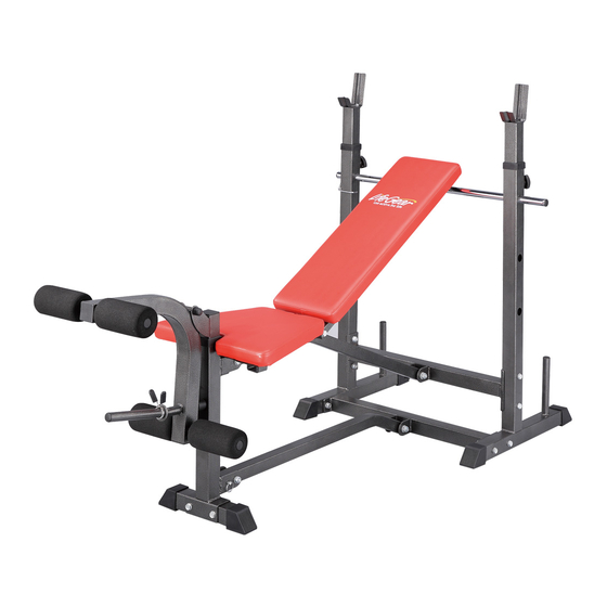
- Page 1 LifeGear F1 body/BENCH ITEM NO.: 76100 OWNER’S MANUAL IMPORTANT: Read all instructions carefully before using this product. Retain this owner’s manual for future reference. The specifications of this product may vary from this photo, subject to change without notice. 2014, Aug.
-
Page 2: Table Of Contents
TABLE OF CONTENTS WARRANTY ------------------------------------------------------------------------------- 2 IMPORTANT SAFETY INSTRUCTIONS ------------------------------------------- 3 PARTS LIST ------------------------------------------------------------------------------- 4 HARDWARE PACKING LIST --------------------------------------------------------- 5 TOOLS ------------------------------------------------------------------------------------- 5 OVERVIEW DRAWING ---------------------------------------------------------------- 6 ASSEMBLY INSTRUCTIONS -------------------------------------------------------- 7 ADJUSTMENTS ------------------------------------------------------------------------- 13 STORAGE --------------------------------------------------------------------------------- 14 MAINTENANCE -------------------------------------------------------------------------- 14 WARM UP AND COOL DOWN ROUTINE ----------------------------------------- 15... -
Page 3: Warranty
ONE YEAR LIMITED WARRANTY LifeGear Inc. warrants to the original purchaser that this product is free from defects in material and workmanship when used for the purpose intended, under the conditions that it has been installed and operated in accordance with LifeGear's Owner's Manual. LifeGear's obligation under this warranty is limited to replacing or repairing free of charge, any parts which may prove to be defective under normal home use. -
Page 4: Important Safety Instructions
IMPORTANT SAFETY INSTRUCTIONS Basic precautions should always be followed, including the following important safety instructions when using this equipment. Read all instructions before using this equipment. Read all instructions and follow it carefully before using this equipment. Make sure the equipment is properly assembled and tightened before use. -
Page 5: Parts List
PARTS LIST Description Qty No. Description 001 Rear Frame 2 023 Leg Developer End Cap 50x50 002 Adjustable Weight Crutch 2 024 Bumper 003 Upper Support Tube 1 025 Spring Clip 004 Lower Support Tube 1 026 Triangle Knob 005 Adjustable Bar 1 027 Round Knob 006 Seat Support Tube 1 028 Square End Cap 25x25... -
Page 6: Hardware Packing List
HARDWARE PACKING LIST Hardware Bag (32) Hexagon Bolt (33) Washer Ø10 (34) Hexagon Nylon (35) Hexagon Bolt 4 PCS M10x80 Lock Nut M10 M10x70 2 PCS 2 PCS 8 PCS (36) Hexagon Bolt (37) Hexagon Bolt (38) Hexagon Bolt (39) Hexagon Bolt M10x75 M10x140 M10x190... -
Page 7: Overview Drawing
OVERVIEW DRAWING 41 32 28 41... -
Page 8: Assembly Instructions
ASSEMBLY INSTRUCTIONS Tool: 2 Wrenches (17-19) Step 1 Attach the Upper Support Tube (3) onto the Rear Frames (1) with four M10x70 Hexagon Bolts (35), four M10 Hexagon Nylon Lock Nuts (41), and eight Ø10 Washers (42). Tighten bolts and nuts with two 17-19 Wrenches provided. Attach the Lower Support Tube (4) onto the Rear Frames (1) with four M10x70 Hexagon Bolts (35), four M10 Hexagon Nylon Lock Nuts (41), and eight Ø10 Washers (42). - Page 9 Tool: 2 Wrenches (17-19) Step 2 Attach the Front Frame (10) onto the Front Base Tube (9) with two M10x75 Hexagon Bolts (36), two M10 Hexagon Nylon Lock Nuts (41), and four Ø10 Washers (42). Tighten bolts and nuts with two 17-19 Wrenches provided. Install two Foot End Caps (19) onto the Front Base Tube (9).
- Page 10 (32) Hexagon Bolt M10x80 (33) Washer Ø10 (34) Hexagon Nylon Lock Nut M10 2 PCS 4 PCS 2 PCS (19) Foot End Cap (43) Ring Pin Ø10x65 2 PCS 1 PC ․․․․․․․․․․․․․․․․․․․․․․․․․․․․․․․․․․․․․․․․ Tool: 2 Wrenches (17-19) Step 3 Attach two Seat Pad Tubes (17) and two Backrest Tubes (16) onto the center bar of the Seat Support Tube (6) with one M10x190 Hexagon Bolt (38), one M10 Hexagon Nylon Lock Nut (41), and two Ø10 Washers (42).
- Page 11 Tool: 2 Wrenches (17-19) Step 4 Attach the U Shaped Seat Adjustment (8) onto the Seat Pad Tubes (17) with one M10x140 Hexagon Bolt (37), one M10 Hexagon Nylon Lock Nut (41), and two Ø10 Washers (42). Tighten bolt and nut with two 17-19 Wrenches provided. Insert the Ø10x65 Ring Pin (43) into the holes on the U Shaped Seat Adjustment (8) and Seat Support Tube (6) to lock the Seat Pad Tubes (17) in place.
- Page 12 Tool: 2 Wrenches (10-14) Step 5 Attach the Backrest (14) onto the Backrest Tubes (16) with four M6x40 Hexagon Bolts (39) and four Ø6 Washers (40). Tighten bolt and nut with one 10-14 Wrench provided. Attach the Seat Pad (15) onto the Seat Pad Tubes (17) with four M6x40 Hexagon Bolts (39) and four Ø6 Washers (40).
- Page 13 Tool: 2 Wrenches (17-19) Step 6 Insert the Leg Height Adjustable Tube (13) into the top square hole of the Front Frame (10). Adjust the position and insert the Round Knob (27). Turn the Round Knob (27) in the clockwise direction to tighten. Attach the Leg Developer (12) onto the Leg Height Adjustable Tube (13) with one M10x75 Hexagon Bolt (36), one M10 Hexagon Nylon Lock Nut (41), and two Ø10 Washers (42).
-
Page 14: Adjustments
ADJUSTMENTS Round Knob Adjusting the Leg Height Adjustable Tube Turn the Round Knob in a counterclockwise direction until it can be pulled out. Pull out the Round Knob and then slide the Leg Height Adjustable Tube up or down direction to the suitable position. -
Page 15: Storage
STORAGE For your storage convenience, the bench can be folded up to place in a storage area. Remove the Adjustable Bar (5) from the Rear Frames (1) and pull out the Ring Pin (43) from the Front Frame (10). Then pull the Seat Support Tube (6) and Base Support Tube (7) all the way up in the vertical position. -
Page 16: Warm Up And Cool Down Routine
WARM UP AND COOL DOWN ROUTINE The WARM-UP is an important part of any workout. The purpose of warming up is to prepare your body for exercise and to minimize injuries. Warm up for two to five minutes before aerobic exercising. It should begin every session to prepare your body for more strenuous exercise by heating up and stretching your muscles, increasing your circulation and pulse rate, and delivering more oxygen to your muscles. - Page 17 QUADRICEPS STRETCH With one hand against a wall for balance, reach behind you and pull your right foot up. Bring your heel as close to your buttocks as possible. Hold for 15 counts and repeat with left foot. INNER THIGH STRETCH Sit with the soles of your feet together and your knees pointing outward.
Need help?
Do you have a question about the F1 Body/BENCH and is the answer not in the manual?
Questions and answers