
Subscribe to Our Youtube Channel
Related Manuals for SSV Works Polaris RZR XP 1000


Summary of Contents for SSV Works Polaris RZR XP 1000
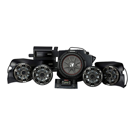
- Page 1 Disassembly, Wire and Amplifier Plate Installation Glovebox Subwoofer Installation Kick Panel Speakers Installation Cage Mount Speakers Installation MRB3 and Dash Kit Installation...
- Page 3 All SSV Works enclosures are covered by a limited lifetime warranty against defects in instructions completely before material or workmanship. All SSV Works Electronics are covered by a limited 1 year warranty installation to avoid possible injury, or against defects in material or workmanship. All Kicker Speakers are covered by a limited 1 damage to the accessory or vehicle.
- Page 4 PANELS AND DASH DISASSEMBLY A. Remove all seats by releasing the handle behind each seat, B. Disconect the negative battery cable from the battery. push forward slightly while lifting up. C. Remove hood by turning locking pins and lifting up. D.
- Page 5 PANELS AND DASH DISASSEMBLY G. Remove the factory dash pocket by first extracting the 10mm bolt on the dash frame (G1). Then pull out the dash pocket with bracket attached (G2) - NOTE this bracket will no longer be used for any part of this installation. Save this screw as it will be use later during the amp plate installation. Extract (2) screws securing the sub dash (G3).
- Page 6 RUNNING AMP POWER CABLE AND REAR SPEAKER WIRE A. Unwrap the tape and pull the rubber wire grommet out of the firewall. B. Pull the MRB3 POWER and GROUND wires through the rubber grommet and feed through the hole in the firewall to the power strip located on the opposite side of the firewall.
- Page 7 RUNNING AMP POWER CABLE AND REAR SPEAKER WIRE TOP VIEW UNDERNEATH VIEW E. Route the front speaker wire through the opening where the firewall and roll cage bar meet on both the driver and passenger side. Leave these wires loose until the front speaker pods are to be installed.
- Page 9 WARRANTY INFORMATION: Please read and understand these All SSV Works enclosures are covered by a limited lifetime warranty against defects in material or instructions completely before workmanship. All SSV Works Electronics are covered by a limited 1 year warranty against defects installation to avoid possible injury, or in material or workmanship.
- Page 10 A. Remove the ten T40 Torx bolts that secure the 2 piece fender. B. Remove the two 10mm bolts that secure factory glove box and Note: there is one screw inside the fender well. Remove the remove the factory glove box two additional screws from the striker plate, slide fender up the cage rail and secure C.
- Page 11 H. For 2014 model year vehicles remove the factory glove box G. For 2015-up model year vehicles, install the supplied bracket using door latch. Mount the latch to the supplied bracket and the short screws provided and adjust forward or back so glove box secure to the enclosure using the short screws provided latch closes tight J.
- Page 13 All SSV Works enclosures are covered by a limited lifetime warranty against defects in instructions completely before material or workmanship. All SSV Works Electronics are covered by a limited 1 year warranty installation to avoid possible injury, or against defects in material or workmanship. All Kicker Speakers are covered by a limited 1 damage to the accessory or vehicle.
- Page 14 A. Using the utility knife or another cutting tool cut off the two plastic factory nubs in the foot well, cut these as smooth as you can to the panel. NOTE: If pod does not come pre-installed with speaker, do not use provided paper templates. Use the pod mounting holes as your drill template. Hold the pod in position and mark the drill holes through the empty pod using a scribe tool.
- Page 15 C. Drill a pilot hole at the places just marked with a 1/8” drill bit. Then follow up by using a 1/4” drill bit in the lower pilot hole (for mounting the pod) and a 1/2” drill bit in the upper pilot hole (for speaker cable). D.
- Page 16 E. Drill a pilot hole at the places just marked with a 1/8” drill bit. Then follow up by using a 1/4” drill bit for both pilot holes (for mounting the pod). F. Route the speaker cable attached to the pod through the inside G.
- Page 17 RZ3-F65 2017 Polaris RZR Kick Pod, Cut Template Driver Outside Template Drill Point Drill Point Cut along parimeter...
- Page 21 RZ3-F65 2017 Polaris RZR Kick Pod, Cut Template Passenger Outside Template Drill Point Drill Point Cut along parimeter...
- Page 25 All SSV Works enclosures are covered by a limited lifetime warranty against defects instructions completely before in material or workmanship. All SSV Works Electronics are covered by a limited 1 year installation to avoid possible injury, or warranty against defects in material or workmanship. All Kicker Speakers are covered damage to the accessory or vehicle.
- Page 26 A. Find the best orientation for the speaker on your bar and B. Loosely install the clamp base to the cage mount pod with the screw in the Set Screws in the OPPOSITE holes of where the two (2) M6 hex head bolts and washers, place the cage mount clamp will install into.
- Page 27 D. From the rear of the center console, route the B-H1150 E. Route the speaker wire away from any moving parts and any harness up to each speaker pod and connect. sharp metal, then connect to the amplifi er F. Connect the B-H1151 speaker harness to the amplifi er...
- Page 29 All SSV Works enclosures are covered by a limited lifetime warranty against defects in instructions completely before material or workmanship. All SSV Works Electronics are covered by a limited 1 year warranty installation to avoid possible injury, or against defects in material or workmanship. All Kicker Speakers are covered by a limited 1 damage to the accessory or vehicle.
- Page 30 A. Take the MRB3 Remote and pass the din cable through the dash kit panel. Once MRB3 remote is laying fl at on the dash panel pass (2) M3 Screws through the remote and kit panel. Flip the kit around and use (2) M3 washers and (2) M3 Nuts to secure the MRB3 down into position. Do not over tighten the nuts, this can cause damage to the dash kit panel.
- Page 31 Polaris RZR XP 1000 & 900 USB/AUX Input Port A. Unscrew and remove the plastic nut from the port. Make sure to B. Make sure all harness connectors are unplugged from the dash open the fuse holder and remove the fuse so the nut will fi t through it.
- Page 32 40A fuse, screw the 2 screws back in and reattach the fuse holder top. column away from the drive shaft. THIS CONCLUDES THE INSTALLATION PROCESS. REPLACE THE FACTORY PANELS AND SEATS. QUESTIONS? PLEASE CONTACT SSV WORKS AT 818-991-1778 OR EMAIL SUPPORT@SSVWORKS.COM © 2018 SSV Works, Oxnard, CA 93030 RZ3-5K Rev. D 2-1-18...
Need help?
Do you have a question about the Polaris RZR XP 1000 and is the answer not in the manual?
Questions and answers