Advertisement
Quick Links
SSV WORKS, 2610 Calle Quetzal, Camarillo, CA 93012
www.SSVworks.com | Phone: 818-991-1778 | Fax: 866-293-6751
4
pg
Panel
Disassembly
6
pg
Dash Speaker Panel
Installation
7
pg
JVC MR1
Installation
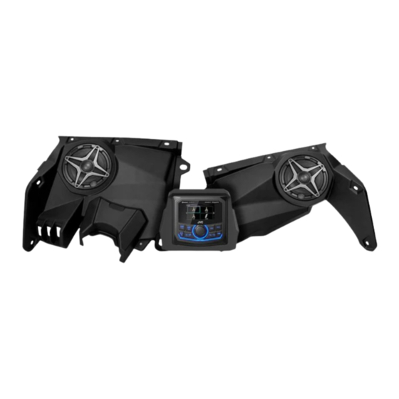
2017-2024 Can Am Maverick X3
Maverick X3
X32-PHZ1A
Phase 1, A-Spec, 2-Speaker
Audio Kit with JVC MR1
1
Advertisement

Related Manuals for SSV Works X32-PHZ1A


Summary of Contents for SSV Works X32-PHZ1A
- Page 1 X32-PHZ1A 2017-2024 Can Am Maverick X3 Phase 1, A-Spec, 2-Speaker Audio Kit with JVC MR1 SSV WORKS, 2610 Calle Quetzal, Camarillo, CA 93012 www.SSVworks.com | Phone: 818-991-1778 | Fax: 866-293-6751 Maverick X3 Panel Disassembly Dash Speaker Panel Installation JVC MR1...
-
Page 2: Parts List
All SSV Works enclosures are covered by a limited lifetime warranty against defects in instructions completely before material or workmanship. All SSV Works Electronics are covered by a limited 1 year warranty installation to avoid possible injury, or against defects in material or workmanship. Labor for replacement of defective components damage to the accessory or vehicle. - Page 3 All SSV Works enclosures are covered by a limited lifetime warranty against defects instructions completely before in material or workmanship. All SSV Works Electronics are covered by a limited 1 year installation to avoid possible injury, or warranty against defects in material or workmanship. Labor for replacement of defective damage to the accessory or vehicle.
- Page 4 PANELS AND DASH DISASSEMBLY A. To remove the seat, use a 13mm socket and wrench to remove front (2) bolt and nut, and use a 18mm socket to remove (2) rear nuts and seat belt nut ( repeat on other seat) B.
- Page 5 E. Remove gas cover on the passenger side to expose a 10mm nut. Unscrew with a wrench and T30 torx driver. E2. Using panel removal tool unsnap (2) push clips on the driver and passenger side dash covers. Unscrew the (4) T30 screws on the passenger side, and (7) T30 screws on the driver side.
- Page 6 DASH SPEAKER PANEL INSTALLATION TOOLS NEEDED FOR INSTALLATION - T20 & T30 Torx Driver - 8, 10 & 13mm Socket Wrench Refer to the X3-DP6K installation manual included in the kit for a detailed installation process of the dash speaker panels. RUNNING WIRE HARNESSES JVC MR1 POWER HARNESS Connect the B-H2368 SSV to JVC adapter...
- Page 7 DASH SPEAKER PANEL AUDIO CABLES Run the B-H2368 SSV to JVC adapter harness from the JVC radio to the B-H1909 front speaker harness and plug in the dash panel speakers. DASH KIT ASSEMBLY A. Set the base plate on the dash. Press the (4) drill guides onto the base plate B.
- Page 8 D. Reset the base plate, trace the outline of the baseplate circle. E. Cut out the traced circle. Limit speed and depth of cutting device to avoid damaging any wiring. F. Place (4) M6 T30 screws and washers into each drilled hole. Fasten G.
- Page 9 J. Place the MR1 into the DMR1. When placing the MR1 into the dash K. Secure the MR1 with the (4) M3.5 screws provided with the MR1. mount, feed slack wiring back into the dash cavity cut out. This will The top (2) screws will thread into the DMR1.
- Page 10 MR1 power harness to the B-H1909 front speaker harness. THIS CONCLUDES THE INSTALLATION PROCESS. REPLACE THE FACTORY PANELS AND SEATS. QUESTIONS? PLEASE CONTACT SSV WORKS AT 818-991-1778 OR EMAIL SUPPORT@SSVWORKS.COM © 2024 SSV Works, Camarillo, CA 93012 X32-PHZ1A 7-30-24...
Need help?
Do you have a question about the X32-PHZ1A and is the answer not in the manual?
Questions and answers