
Subscribe to Our Youtube Channel
Related Manuals for enphase IQ6-60-2-US


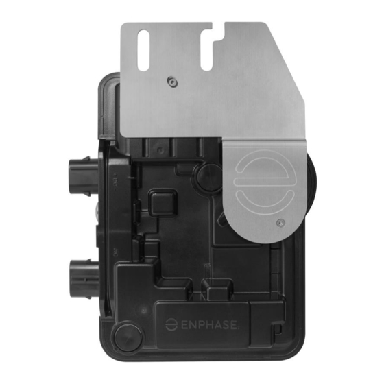
Summary of Contents for enphase IQ6-60-2-US
- Page 1 INSTALLATION AND OPERATION MANUAL Enphase IQ 6 and IQ 6+ Micros December 27, 2017 141-00034-01...
-
Page 2: Fcc Compliance
User documentation is updated frequently; Check the Enphase website (enphase.com/support) for the latest information. To ensure optimal reliability and to meet warranty requirements, the Enphase Microinverter must be installed according to the instructions in this manual. For warranty text refer to enphase.com/warranty. -
Page 3: Table Of Contents
Step 6: Connect the Microinverters ........................ 18 Step 7: Terminate the Unused End of the Cable.................... 19 Step 8: Complete Installation of Junction Box or an Enphase Q Aggregator ..........20 Step 9: Connect the PV Modules ........................20 Step 10: Energize the System ........................21 Set Up and Activate Monitoring ........................ - Page 4 Specifications ..............................35 IQ6-60-2-US Microinverter Specifications ....................35 IQ6PLUS-72-2-US Microinverter Specifications ..................38 Q Cable Specifications ..........................40 Enphase Connector Ratings ........................40 Enphase Installation Map ..........................41 Sample Wiring Diagram: ..........................42 © 2017 Enphase Energy Inc. All rights reserved. 141-00034-01...
-
Page 5: Important Safety Information
Double-insulated Safety and Advisory Symbols To reduce the risk of electric shock, and to ensure the safe installation and operation of the Enphase IQ System, the following safety symbols appear throughout this document to indicate dangerous conditions and important safety instructions. - Page 6 IQ 6 / IQ 6+ Micro Installation and Operation Do not use Enphase equipment in a manner not specified by the manufacturer. Doing so may cause DANGER: Risk of death or injury to persons, or damage to equipment. electric shock.
-
Page 7: Pv Rapid Shutdown Equipment (Pvrse)
When installing the Enphase Q Cable, secure any loose cable to minimize tripping hazard. When looping the Enphase Q Cable, do not form loops smaller than 4.75” (12 cm) in diameter. NOTES: Provide support for the Enphase Q-Cable every 1.8m (6 feet). -
Page 8: The Enphase Iq System
The Enphase IQ System The Enphase IQ System includes: • Enphase IQ 6 and/or IQ 6+ Micros The smart grid ready IQ6 and IQ6+ Micros convert the DC output of the PV module into grid-compliant AC power. • Enphase IQ Envoy™ (ENV-IQ-AM1-240) The Enphase IQ Envoy is a communication device that provides network access to the PV array. -
Page 9: How The Enphase Iq 6 And Iq 6+ Micros Work
PV module. System Monitoring Once you install the Enphase IQ Envoy and provide an internet connection through a broadband router or modem, the Enphase IQ Microinverters automatically begin reporting to Enlighten. Enlighten presents current and historical system performance trends, and informs you of PV system status. -
Page 10: Planning For Microinverter Installation
IQ 6 / IQ 6+ Micro Installation and Operation Planning for Microinverter Installation The Enphase IQ 6 Micro is compatible with 60-cell PV modules, and the IQ 6+ Micro supports PV modules with 60 or 72 Cells. Both install quickly and easily. The microinverter housing is designed for... -
Page 11: Branch Circuit Capacity
Select the correct wire size based on the distance from the beginning of the microinverter AC branch circuit to the breaker in the load center. Enphase recommends a voltage rise total of less than 2% for the sections from the microinverter AC branch circuit to the breaker in the load center. -
Page 12: Lightning And Surge Suppression
For this reason, Enphase recommends that you protect your system with a lightning and/or surge suppression device. In addition to having some level of surge suppression, it is also important to have insurance that protects against lightning and electrical surges. -
Page 13: Parts And Tools Required
• Enphase Installer Toolkit Download the Enphase Installer Toolkit mobile app and open it to log in to your Enlighten account. With this app, you can scan microinverter serial numbers and connect to the IQ Envoy to track system installation progress. To download, go to enphase.com/toolkit... -
Page 14: Enphase Microinverter Installation
IQ 6 / IQ 6+ Micro Installation and Operation Enphase Microinverter Installation Installing the Enphase IQ 6 and IQ 6+ Micros involves several key steps. Each step listed here is detailed in the following pages. Step 1: Position the Enphase Q Cable... -
Page 15: Step 1: Position The Enphase Q Cable
208 V Single-Phase 183 to 229 VAC B. Install an Enphase Q Aggregator or junction box at a suitable location on the racking. See the Enphase Q Aggregator Quick Install Guide. C. Provide an AC connection from the Enphase Branch Aggregator back to the electricity network using equipment and practices as required by local jurisdictions. -
Page 16: Step 3: Mount The Microinverters
6 mm (¼”) mounting hardware: 5 N m (45 to 50 in-lbs.) • 8 mm (5/16”) mounting hardware: 9 N m (80 to 85 in-lbs.) • When using UL 2703 mounting hardware, use the manufacturer’s recommended torque value DC Connector AC Connector © 2017 Enphase Energy Inc. All rights reserved. 141-00034-01... -
Page 17: Step 4: Create An Installation Map
Each Enphase Microinverter, Envoy, and Battery have a removable serial number label. Build the installation map by peeling the serial number labels from the microinverter mounting plates and placing the labels on the map. You will also place the Enphase IQ Envoy and IQ Battery serial number on the map after installation. -
Page 18: Step 5: Manage The Cabling
Step 6: Connect the Microinverters A. Connect the microinverter. Listen for a click as the connectors engage. B. Cover any unused connector with Enphase Sealing Caps. Listen for a click as the connectors engage. WARNING: Risk of electric shock. Risk of fire. Install sealing caps on all unused AC connectors as these connectors become live when the system is energized. -
Page 19: Step 7: Terminate The Unused End Of The Cable
IQ 6 / IQ 6+ Micro Installation and Operation Step 7: Terminate the Unused End of the Cable Terminate the unused end of the Enphase Q Cable as follows. 13mm Terminator Body A. Remove 13 mm (½ inch) of the cable sheath from the conductors. -
Page 20: Step 8: Complete Installation Of Junction Box Or An Enphase Q Aggregator
Step 8: Complete Installation of Junction Box or an Enphase Q Aggregator A. Connect the Enphase Q Cable into the Enphase Q Aggregator. The Enphase Q Cable uses the following wiring color code. A ground lug is provided on the Q Aggregator for convenient module/rack/balance of system (BOS) grounding. -
Page 21: Step 10: Energize The System
“DC Resistance Low – Power Off Condition” on page 22. Set Up and Activate Monitoring Refer to the Enphase IQ Envoy Quick Install Guide to install the IQ Envoy and set up system monitoring and grid management functions. This guide leads you through the following: •... -
Page 22: Troubleshooting
If a microinverter registers a “DC Resistance Low - Power Off” condition, you can attempt to clear this condition. If the condition does not clear after you perform the following procedure, contact Enphase Energy customer support at enphase.com/en-us/support/contact. -
Page 23: Other Faults
The app then indicates that a clear message was sent. Other Faults All other faults are reported to the Envoy. Refer to the Enphase IQ Envoy Installation and Operation Manual at enphase.com/support for troubleshooting procedures. -
Page 24: Troubleshoot An Inoperable Microinverter
L1, L2 to ground 106 to 132 VAC E. Using an Enphase disconnect tool, disconnect the AC cable for the microinverter in question from the Enphase Q Cable. F. Verify that utility power is present at the microinverter by measuring line to line and line to ground at the Enphase Q Cable connector. -
Page 25: Disconnect A Microinverter
NOTE: Take care when measuring DC current as most clamp-on meters must be zeroed first and tend to drift with time. E. Disconnect the PV module DC wire connectors from the microinverter using the Enphase disconnect tool. F. If present, loosen and/or remove any bonding hardware. -
Page 26: Install A Replacement Microinverter
• Do not mount the microinverter upside down. • Do not expose the AC or DC connectors (on the Enphase Q Cable connection, PV module, or the microinverter) to rain or condensation before the connectors are mated. C. Torque the mounting fasteners to the values shown. Do not over torque. - Page 27 K. Log in to Enlighten to use Enlighten’s Array Builder to add the newly detected microinverter to the virtual array. L. Ship the old microinverter to Enphase using the supplied return-shipping label. © 2017 Enphase Energy Inc. All rights reserved.
-
Page 28: Ordering Replacement Parts
These parts are available from your Enphase distributor. Enphase Q Cable Planning and Ordering The Enphase Q Cable is a continuous length of 12 AWG, double insulated, outdoor-rated cable with integrated connectors for microinverters. These connectors are preinstalled along the Q Cable at intervals to accommodate varying PV module widths. -
Page 29: Enphase Q Cable Accessories
IQ 6 / IQ 6+ Micro Installation and Operation Enphase Q Cable Accessories The Enphase Q Cable is available with several accessory options for ease of installation, including: • Enphase Q Aggregator: (Q-BA-3-1P-60) Aggregates up to three fully populated 20A branch circuits and supports solar arrays of up to 11.5kWac with a single rooftop aggregator... -
Page 30: Technical Data
Technical Data Technical Considerations Be sure to apply the following when installing the Enphase IQ 6 and/or IQ 6+ Micro System: WARNING: Risk of equipment damage. You must match the DC operating voltage range of the PV module with the allowable input voltage range of the Enphase Microinverter. -
Page 31: Grid Interconnection Details
Grid Interconnection Details Both the Enphase IQ 6 and the IQ 6+ Microinverter are grid support interactive inverters. This type of inverter is also known as a Grid Support Utility Interactive Inverter (GSUII). The IQ 6 and IQ 6+ also comply with California Rule 21 - 2016 and Hawaii Rule 14H - 2017. -
Page 32: Volt Var Characteristics
Low voltage 1 - magnitude percentage Low voltage 2 - time 149.800 0.000 150.0 Low voltage 2 - magnitude percentage Low voltage 3 - time 29.800 0.000 30.0 Low voltage 3 - magnitude percentage © 2017 Enphase Energy Inc. All rights reserved. 141-00034-01... -
Page 33: Sa10: Low/High Frequency Ride Through (L/H Frt) And Must Trip Settings
Adjustment Range Units Minimum AC EPS voltage range P.U. 0.80 Maximum EUT input voltage P.U. 1.20 AC power Reactive power absorption (inductive, under excited) Reactive power production (capacitive, overexcited) Slope VAr/V Deadband © 2017 Enphase Energy Inc. All rights reserved. 141-00034-01... -
Page 34: Sa14: Frequency-Watt (Fw)
SA15: Volt-Watt (VW) Adjustment Range Units Adjustment range of the start of the curtailment function 130.0 121.0 Adjustment range of the stop of the curtailment function 138.0 123.0 Slope of voltage curtailment %Prated/V © 2017 Enphase Energy Inc. All rights reserved. 141-00034-01... -
Page 35: Specifications
Extended frequency range Maximum AC output over current protection device No enforced DC/AC ratio. See the compatibility calculator at enphase.com/en-us/support/module-compatibility Nominal Voltage Range can be extended if required by the utility. © 2017 Enphase Energy Inc. All rights reserved. 141-00034-01... - Page 36 When using UL 2703 mounting hardware, use the manufacturer’s recommended torque value Cooling Natural convection - no fans Relative humidity range 4% to 100% condensing Approved for wet locations Pollution degree © 2017 Enphase Energy Inc. All rights reserved. 141-00034-01...
- Page 37 NEC 690. Integrated AC disconnect The AC connector has been evaluated and approved for use as the load-break disconnect required by NEC 690. © 2017 Enphase Energy Inc. All rights reserved. 141-00034-01...
-
Page 38: Iq6Plus-72-2-Us Microinverter Specifications
Low AC voltage trip limit accuracy Frequency trip limit accuracy ±0.1 Trip time accuracy milliseconds ±33 Overvoltage class AC port AC port backfeed under single fault Power factor at rated power © 2017 Enphase Energy Inc. All rights reserved. 141-00034-01... - Page 39 The DC connector has been evaluated and approved for use as the load-break disconnect required by NEC 690. Integrated AC disconnect The AC connector has been evaluated and approved for use as the load-break disconnect required by NEC 690. © 2017 Enphase Energy Inc. All rights reserved. 141-00034-01...
-
Page 40: Q Cable Specifications
Cable connector dimensions Enphase Connector Ratings Enphase connectors in the following table have a maximum current of 20A, a maximum OCPD of 20 A, and an ambient temperature range of -40° to +79° C (-40° to +174.2° F). Part Number... -
Page 41: Enphase Installation Map
IQ 6 / IQ 6+ Micro Installation and Operation Enphase Installation Map © 2017 Enphase Energy Inc. All rights reserved. 141-00034-01... -
Page 42: Sample Wiring Diagram
IQ 6 / IQ 6+ Micro Installation and Operation Sample Wiring Diagram: © 2017 Enphase Energy Inc. All rights reserved. 141-00034-01...
Need help?
Do you have a question about the IQ6-60-2-US and is the answer not in the manual?
Questions and answers