Advertisement
Q U I C K I N S T A L L G U I D E
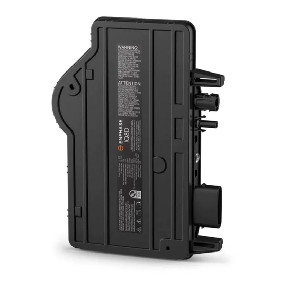
Install Enphase IQ8D Microinverters
To install Enphase IQ8D Microinverters, read and follow all warnings and instructions in this guide and in the Commercial PV Design Guide IQ8D Micro-
inverter System at: enphase.com/support. Each IQ8D Microinverter supports two series-connected PV modules, and is a small commercial solution for
grid-tied, three-phase, 208 V PV applications. Safety warnings are listed on the back page of this guide.
The Enphase IQ8D Microinverter listed in this guide do not require grounding electrode conductors (GEC), and equipment grounding conductors (EGC). The
IQ8D Microinverter has a Class II double-insulated rating, which includes ground fault protection (GFP). To support GFP, use only PV modules equipped with
DC cables labeled PV Wire or PV Cable.
IMPORTANT: The Enphase IQ8D Microinverters include AC and DC connectors integrated into the microinverter bulkhead. The AC port of the IQ8D
microinverter connects to an Enphase QD Cable. Enphase IQ8D Microinverter bulkhead and adapter cable male, female DC connectors must only be
mated with the identical type and manufacturer brand of male/female connector. IQ8D Microinverter has Enphase EN4 bulkhead for DC connection and
bulkhead adapter cable for EN4 to Staubli MC4 connection. The EN4 Bulkhead has been evaluated by UL for intermatability with TE PV4-S SOLARLOK
connectors.
Note: Installer must check the manufacturing date of the products to ensure that the installation date is within one year of the manufactured date of
the products. Contact your local distributor to validate the date code.
PREPARATION
A ) Download the Enphase Installer App and open it to log in
to your Enphase Installer App account. With this app, you
can scan microinverter serial numbers and connect to
the Enphase IQ8D Commercial Gateway to track system
installation progress. To download, go to
installerapp
or scan the QR code at right.
B ) Refer to the following table and check PV module electrical compati-
bility at: enphase.com/en-us/support/module-compatibility.
Model
DC connector
IQ8D-72-E-US EN4 Locking
(TE PV4S-SOLARLOK)
C ) In addition to the Enphase Microinverters, PV modules and racking,
you will need these Enphase items:
• Enphase IQ8D Commercial Gateway (model ENV-IQ8D-AM3-3P):
required to monitor solar production.
• Enphase Mobile Connect™ (model CELLMODEM-M1-06-SP-05 or
CELLMODEM-M1-06-AT-05) 4G-based LTE-M modem. Contact
Enphase for data plan options.
• If your PV modules have TE PV4S SOLARLOK connectors, you may
plug them directly into the IQ8D Microinverter with EN4 bulkhead. An
Enphase bulkhead adapter (ECA-EN4-S22 : EN4 (TE PV4-S SOLARLOK)
150mm/5.9" to Staubli MC4 adapter cable pair) is provided by default
with the IQ8D for PV modules with Staubli MC4 connectors. For other
connections, the following Enphase DC adapter options are available.
DC Adapter Cable
EN4 (TE PV4-S SOLARLOK)
150mm/5.9" to Staubli MC4 (Default
Supply)
EN4 (TE PV4-S SOLARLOK) to
150mm/5.9" non-terminated cable
(Pack of 12 pairs - Optional)
EN4 (TE PV4-S SOLARLOK)
1000mm/39.4" to Staubli MC4 (Pack
of 12 pairs - Optional)
EN4 (TE PV4-S SOLARLOK)
1800mm/70.9" to Staubli MC4 (Pack
of 12 pairs - Optional)
EN4 (TE PV4-S SOLARLOK)
2700mm/106.3" to Staubli MC4 (Pack
of 12 pairs - Optional)
• Tie wraps or QD Cable clips (ET-CLIP-100).
• Enphase Sealing Caps (QD-SEAL-10): for any unused connectors on the
Enphase QD Cable.
• Enphase Terminator (QD-TERM-10): Typically 1 Terminator (End feeding
branch circuit) or 2 Terminator (Center feeding branch circuit) required
per branch circuit.
• Enphase Center tap adapter cable QD-LINKFW-10 (For IQ8D systems
with 15.1 ft QD Cable SKU (QD-12-42-63).
enphase.com/
PV module cell count
Pair with two series-
connected 60- or 72-cell PV
modules with full or split cell
configuration
Part
Model SKU
number
860-
ECA-EN4-S22
00311
860-
ECA-EN4-FW-12
00777
860-
ECA-EN4-S22-10-12
00792
860-
ECA-EN4-S22-18-12
00793
860-
ECA-EN4-S22-27-12
00794
Enphase Field Wireable Connectors: Male QD-CONN-10M and Female
•
QD-CONN-10F.
• Enphase disconnect tool (QD-DISC-10).
• Enphase QD cable (as listed in the following table):
Cable model
Connector
SKU
spacing
QD-12-10-150
1.4 m (4.6 ft)
QD-12-20-135
2.4 m (7.9 ft)
QD-12-42-63
4.6 m (15.1 ft)
D ) Field wireable connectors are pre-installed at the ends of the QD cables
to increase the cable length beyond the connector limit mentioned in
above table. The field wireable connectors are protected with sealing
caps. The sealing caps must be removed only when you are increasing
cable length using the field wireables at the cable end.
Warning: Do not remove sealing caps from the cable end field wireable
connectors if they are not used to increase cable length.
E ) Check that you have these other items:
• AC junction box.
• Tools: screwdrivers, wire cutter, voltmeter, torque wrench, sockets,
Screwdriver with blade width 4 mm to 3.2 mm (1/8") and wrenches
for mounting hardware.
F ) Protect your system with lightning / surge suppression devices. It is also
important to have insurance that protects against lightning / electrical surges.
G ) Plan your AC branch circuits with a maximum of 9 IQ8D Microinverters
per three-phase branch, with each branch protected by a 3-pole 20A
over-current protection device (OCPD).
Maximum microinverters per 20A branch circuit
Three Phase
H ) Size the AC wire gauge to account for voltage rise. Select the correct
wire size based on the distance from the beginning of the Enphase
QD Cable to the breaker in the load center. Design for a voltage rise
total of less than 2% for these sections. Refer to the IQ8D Voltage Rise
Technical Brief at
enphase.com/support
Best practice: Center-feed the branch circuit to minimize voltage rise in a
fully-populated branch.
DC connector
AC junction box
PV module
Connectors
orientation
per box
Portrait
150
Landscape
135
Landscape
63
ballast
IQ8D (3 Phase 208 VAC)
9 micros
for more information.
Enphase Terminator
Enphase QD Cable
Enphase IQ8D Microinverter
AC connector
Advertisement
Table of Contents

Subscribe to Our Youtube Channel
Related Manuals for enphase IQ8D


Summary of Contents for enphase IQ8D
- Page 1 Install Enphase IQ8D Microinverters To install Enphase IQ8D Microinverters, read and follow all warnings and instructions in this guide and in the Commercial PV Design Guide IQ8D Micro- inverter System at: enphase.com/support. Each IQ8D Microinverter supports two series-connected PV modules, and is a small commercial solution for grid-tied, three-phase, 208 V PV applications.
-
Page 2: Installation
Position the Enphase QD Cable Vertical Mount A ) Plan each cable segment to allow the drop connectors on the Enphase QD Cable to align with IQ8D Microinverter connected in series with two PV modules. Allow extra length for slack, cable turns, and any obstructions. -
Page 3: Terminate The Unused End Of The Cable
It is a best practice to center-feed the AC supply to the microinverter branch tors. circuit to limit voltage rise to less than 2% for the site. For IQ8D Microinverter B ) Slide the hex nut onto the cable. The grommet inside the terminator system installations with 15.1 ft QD Cable SKU (QD-12-42-63), the voltage rise... -
Page 4: Pv Rapid Shutdown Equipment (Pvrse)
IQ8D Microinverter has detected a PV panel which is operating Flashing outside arc-safe region. B ) Connect positive and negative DC lead from each PV module to the IQ8D orange Microinverter bulkhead DC connectors directly or using the adapter cables. -
Page 5: Microinverter Safety
WARNING: Risk of equipment damage. Enphase male and mount the microinverter upside down. Do not expose female connectors must only be mated with the identical the AC or DC connectors (on the Enphase QD Cable type and brand of male/female connector. IQ8D Microin- ✓...
Need help?
Do you have a question about the IQ8D and is the answer not in the manual?
Questions and answers