enphase IQ8 Design Manual
Commercial microinverter grid-tied pv system
Hide thumbs
Also See for IQ8:
- Installation manual ,
- Installation and operation manual (49 pages) ,
- Installation and commissioning manual (16 pages)
Table of Contents
Advertisement
Advertisement
Table of Contents
Troubleshooting

Related Manuals for enphase IQ8


Summary of Contents for enphase IQ8
- Page 1 DESIGN GUIDE IQ8 Commercial Microinverter grid-tied PV system design guide...
-
Page 2: Corporate Headquarters Contact Information
User documentation is updated frequently; check the Enphase website for the latest information. https:/ /enphase.com/installers/resources/documentation To ensure optimal reliability and to meet warranty requirements, the Enphase microinverter must be installed according to the instructions in this manual. For warranty text refer to enphase.com/installers/resources/warranty... -
Page 3: Table Of Contents
Design considerations for voltage rise ................. 19 2.3.1 Recommendations ........................19 2.3.2 IQ8 Commercial VRise for 208 VAC in QD Cable ..............20 2.3.3 Center tap connection scenarios ....................21 2.3.4 Advantages of center feeding QD Cable AC branch circuit..........22 IQ Gateway Commercial 2 ..................... - Page 4 7.2.1 Method 1: Clear the error using the Enphase Installer Portal ..........61 7.2.2 Method 2: Use the Enphase Installer App to clear the condition ..........61 Troubleshoot an inoperable microinverter ................61 Disconnect a microinverter ....................62 Install a replacement microinverter ..................63 Appendix A: Ampacity calculations for IQ8 Commercial Microinverter system .....
- Page 5 IQ8 Commercial Microinverter grid-tied PV system Branch circuit current calculations ..................64 Appendix B: Phase balancing in IQ8 Commercial installations using the three-phase QD Cable phase rotation ..........................66 AC QD Cable for IQ8 Commercial Microinverter ..............66 9.1.1 Phase rotation for QD Cable ...................... 66 9.1.2...
-
Page 6: Important Safety Information
Double Insulated Safety and advisory symbols To reduce the risk of electric shock, and to ensure the safe installation and operation of the IQ8 Series Microinverters system, the following safety symbols appear throughout this document to indicate dangerous conditions and important safety instructions. -
Page 7: Iq8 Commercial Microinverters Safety Instruction
You must protect each microinverter AC branch circuit with a 20 A maximum breaker as appropriate. Do not use Enphase equipment in a manner not specified by the manufacturer. Doing DANGER: Risk of so may cause death or injury to persons or damage to equipment. - Page 8 DC voltage of the Enphase microinverter. Refer to the Enphase compatibility calculator to verify PV module electrical compatibility with microinverter. Use IQ8 Commercial Series Microinverters only with compatible PV modules as per the Enphase compatibility calculator. Using an electrically incompatible PV module voids Enphase warranty.
- Page 9 • Avoid overly tight bending radii. The minimum bend radii for the DC cable is 8 times cable outer diameter. • Avoid overly tight-sized cable clips for routing. © 2023 Enphase Energy Inc. All rights reserved. November 2023 USG-00026-1.0...
-
Page 10: Enphase Iq8 Commercial Pv System
• Enphase Installer Portal and Enphase Installer App This guide describes the safe installation and operation of the IQ8 Commercial Series Microinverters. NOTE: To ensure optimal reliability and to meet warranty requirements, Enphase microinverters must be installed according to the instructions in this guide. - Page 11 IQ8 Commercial Microinverter grid-tied PV system The following table lists the system components. Table 1: IQ8 Commercial Microinverters system components System Enphase model SKU details component IQ8 Commercial Microinverter IQ8P-3P-72-E-US IQ8H-3P-72-E-US Microinverter ECA-EN4-S22: EN4 (TE PV4-S SOLARLOK) 150 mm/5.9" to Staubli MC4 (Default Supply) ECA-EN4-FW-10-12: EN4 (TE PV4-S SOLARLOK) to 1000 mm/39.4”...
-
Page 12: Iq8 Commercial System Design Considerations
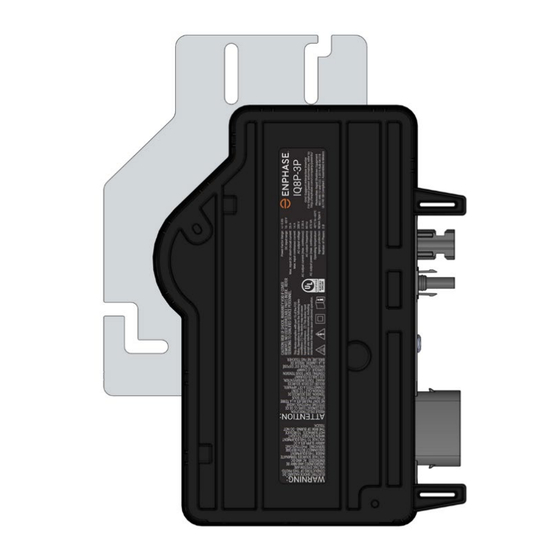
480 watts. Figure 2: IQ8 Commercial Microinverters IQ8 Commercial Microinverters have an output configuration of a 4-pin (L1, L2, L3, and N) AC connector with power on two pins and phase sensing on the other two pins. Three-phase configuration and phase balancing are achieved using the three-phase QD Cable. The following topics describe the design considerations for IQ8 Commercial Microinverters. -
Page 13: Enphase Frame Mount Bracket
For the EN4 to Staubli MC4 connection, DC adapter cables (Part number: ECA-EN4-S22) of length 150 mm (5.91 in) are provided by default with IQ8 Commercial Microinverter. For installations where DC cables from the PV modules are unable to reach the IQ8 Commercial Microinverter, installers can order longer EN4 to Staubli MC4 adapter cables. -
Page 14: Number Of Microinverters Per Branch Circuit
This arrangement alternates between connectors for each drop to achieve self-phase balancing. The QD Cable 4-pin male connectors plug directly into the IQ8 Commercial Microinverters, whose double insulated rating requires no grounding conductors. -
Page 15: Three-Phase Qd Cable Specifications, Cable Types, And Ordering Options
Max voltage count per spacing QD-12-13-120 277 VAC 1.7 m (5.6 ft) Portrait QD-12-20-120 277 VAC 2.4 m (7.9 ft) Landscape QD-12-25-108 277 VAC 2.9 m (9.5 ft) Landscape © 2023 Enphase Energy Inc. All rights reserved. November 2023 USG-00026-1.0... -
Page 16: Design Considerations For Qd Cable Selection
QD Cable if they are not used to increase cable length. 2.2.2 Design considerations for QD Cable selection Each IQ8 Commercial Microinverter supports one compatible PV module. IQ8 Commercial Microinverter system supports multiple positioning and orientation options for PV modules through multiple QD Cable SKUs. -
Page 17: Design Considerations For Qd Accessories
Figure 6: Three-phase Field Wireable QD Connector QD Cable Clip The Enphase QD Cable Clip (ET-CLIP-100) can support one or two QD Cables or Raw QD Cables to a solar mounting rail. This clip has been evaluated with a large selection of racking systems and works with most available rail-based racking systems. - Page 18 Figure 7: QD Cable Clip QD Sealing Caps Cover any unused QD Cable connector with Enphase watertight QD Sealing Caps (QD-SEAL-10). Listen for a click as the connectors engage. Install QD Sealing Caps on all unused AC connectors because these connectors become live when the system is energized.
-
Page 19: Design Considerations For Voltage Rise
This section describes the voltage rise guidelines for dedicated PV branch circuits and methods for calculating the AC line voltage rise when using the Enphase IQ8 Commercial Microinverters and the Enphase QD Cable. Applying proper voltage rise calculations during your system design helps prevent nuisance voltage out-of-range trip issues due to high line voltage conditions. -
Page 20: Iq8 Commercial Vrise For 208 Vac In Qd Cable
2.3.2 IQ8 Commercial VRise for 208 VAC in QD Cable Refer to the following tables to find the VRise in QD Cable for your project based on the number of IQ8 Commercial Microinverters in an AC Branch Circuit. Table 8 through Table 15 below provide VRise values for the IQ8 Commercial Microinverters in an AC branch circuit (with a maximum of 9 microinverters per branch circuit) for multiple QD Cable options. -
Page 21: Center Tap Connection Scenarios
QD connectors for microinverter connection. Select the center tap connector such that a maximum of nine IQ8 Commercial Microinverters are installed on either side of the center tap connector to limit voltage rise <1% in the QD Cable. In case the circuit length itself is less than nine microinverters, the circuit shall be end-terminated, leaving the QD Center Tap connectors unused. -
Page 22: Advantages Of Center Feeding Qd Cable Ac Branch Circuit
Enphase recommends that the total percentage of voltage rise in the AC wiring be a maximum of 2%, with (an inclusive) less than 1% voltage rise in the QD Cable. A fully populated IQ8 Commercial branch circuit has 12 microinverters with IQ8P-3P and 15 microinverters with IQ8H-3P on the AC Branch circuit. -
Page 23: Iq Gateway Commercial 2
Select the center tap connector such that a maximum of 9 IQ8 Commercial Microinverters are installed on either side of the center tap connector to limit voltage rise <1% in the QD Cable. Do not exceed branch circuit sizing mentioned on Page 1 in this guide. -
Page 24: Wiring Iq Gateway Commercial 2 Env2-Iqc2-Am3-3P For Three-Phase Applications
Enphase IQ Microinverter systems use power line communications (PLC) to communicate module-level data between the microinverters and the gateway. The PLC signal is at 110 kHz in an IQ8 Commercial System. In a commercial-scale system, the IQ Gateway Commercial 2 is continuously polling the microinverters for their recent power production, temperature, voltage, amperage, and frequency data. -
Page 25: Design Considerations For Sites With Power Export Limit Requirements
PEL values. Primary Protection An Enphase IQ8 Commercial system can support the Power Export limit by using a PEL Grid profile and an IQ Gateway Commercial 2 with Production CTs installed at solar PV subpanels and Consumption CTs installed at/near the utility service location. -
Page 26: Multiple Gateway Systems
Coupling of the signals can occur between the conductors and conduits when run together, especially on long conduit and wire runs. NOTE: Do not use the PLC scan function on IQ Gateway Commercial 2 to detect IQ8 Commercial Microinverters for a multiple gateway installation. -
Page 27: Internet Connection Options
2.7 Power line filters Enphase offers a 400 A power line filter for IQ8 Commercial System installation. QD-LCF-400-3P is specific for the IQ System power line communication (PLC) frequency. You can use it to filter electrical noise or signals between multiple IQ Gateway Commercial 2s and their respective communication domains and/or noise sources from loads or other devices in commercial and industrial settings. -
Page 28: 400 A Filter (Sku: Qd-Lcf-400-3P)
2.7.1 400 A filter (SKU: QD-LCF-400-3P) The filter must be protected by a 400 A or smaller OCPD. When installing a power line filter in an IQ8 Commercial System, the IQ8 Commercial Microinverters and the IQ Gateway Commercial 2 must ALL be located on the load side of the filter. -
Page 29: Iq8 Commercial System Layout Design
You can consider any array configuration, module orientation, azimuth, and tilt angle for the PV modules. Please note that IQ8 has a single Maximum Power point tracking, and if connected with two series connected modules, both the panels should have the same orientation, azimuth, and tilt angle for maximizing power output. -
Page 30: Pv Load Center Configuration And Location
Microinverters per branch circuit. In case you are skipping a connector, ensure that each branch circuit has IQ8 Commercial Microinverters as multiples of 3 per phase, that is, L1- L2, L2-L3, L3-L1 and within the maximum recommended number of microinverters per 3- pole 20 A circuit. -
Page 31: Location Of Pv Load Center
If you need to extend the leads, refer to the Enphase IQ Gateway Commercial 2 Installation and Operation Guide at enphase.com/support. Do not extend the leads of the production CT. -
Page 32: Iq8 Commercial Microinverter Installation
IQ8 Commercial Microinverter grid-tied PV system 4 IQ8 Commercial Microinverter installation 4.1 Parts and tools required In addition to the IQ8 Commercial Microinverters, PV modules, and racking, you will need the following. Enphase BOM Table 16: QD Cable types/ordering options Enphase IQ Gateway Commercial 2 Required to monitor production. -
Page 33: Iq8 Commercial Microinverter Installation
9. Energize the system. Step 1: Position the Enphase QD Cable A. Plan each cable segment to allow connectors on the QD Cable to align with each IQ8 Commercial Microinverter connected to the PV module. Allow extra length for slack, cable turns, and any obstructions. - Page 34 E. Ensure microinverters are oriented in the correct direction with the correct side facing the solar PV module (bracket side up). F. The Enphase Frame Mount bracket allows you to attach an IQ8 Commercial Microinverter easily and rapidly to the PV module frame. Use the Frame Mount bracket in rail-less or ballasted solar installations.
- Page 35 IQ8 Commercial Microinverter grid-tied PV system Figure 15: Frame Mount bracket The Enphase Frame Mount bracket comes in two sizes, 35 mm (EFM- 35 MM) and 40 mm (EFM-40MM), depending upon the thickness (depth) of the PV module frame. •...
- Page 36 Step 5: Provide an AC connection to the branch circuit Method A: Center-feeding the branch circuit Enphase recommends that the total percentage of voltage rise in the AC wiring be a maximum of 2%, with (an inclusive) less than 1% voltage rise in the QD Cable.
- Page 37 183 to 229 VAC 220 VAC three-phase 198 to 242 VAC Figure 18: Center feeding of AC branch circuit Figure 19: Center feeding of AC branch circuit with link FW connector © 2023 Enphase Energy Inc. All rights reserved. November 2023 USG-00026-1.0...
- Page 38 Use the Enphase three-phase Field Wireable QD Connectors (QD-CONN-10M and QD-CONN- 10F) for end feeding the AC supply to IQ8 Commercial Microinverter branch circuits. OR installers can use off-the-shelf junction boxes for end feeding or center feeding the three-phase AC supply to IQ8 Commercial Microinverter branch circuit.
- Page 39 E/W), racking hardware used for mounting the module, and microinverter mounting hardware. In installations where DC cables from the PV modules are unable to reach the IQ8 Commercial Microinverter, installers can use optional 1-meter EN4 to MC4 extension cable SKUs, which are available in both terminated and non-terminated options.
- Page 40 DC cable length due to the split junction box at the center of the PV module. • Enphase male and female connectors must only be mated with the identical type and manufacturer brand of male/female connector. IQ8 Commercial Microinverter has an Enphase EN4 bulkhead for DC connection and bulkhead adapter cable for EN4 to MC4 connection.
- Page 41 C. Check the LED on the connector side of the microinverter. NOTE: Installers may see numerous ACVOOR (AC voltage out of range) events during the commissioning of IQ8 Commercial Systems if the grid has higher impedance or is operating in a region with wide voltage or frequency regulation.
-
Page 42: Iq8 Commercial System Startup And Commissioning
5 IQ8 Commercial System startup and commissioning 5.1 Startup and commissioning using the Enphase Installer App IQ8 Commercial PV System should be commissioned using Enphase Installer App Version 3.29 or later. • You can install the application using the below links or scan the QR code here. -
Page 43: System Activation Using The Enphase Installer Portal
Enlighten, contact your Enlighten administrator. B. In your Enlighten Dashboard, on the Activations widget, click Add a New System. C. In the Enphase Installer Portal interface, under site activation, select whether the system is residential or commercial. -
Page 44: Array Builder Using Enphase Installer Portal
Figure 24: System activation using Enphase Installer 5.1.2 Array Builder using Enphase Installer Portal Use the Enphase Array Builder to build your virtual array. You can find a link to Array Builder on the System Activation form or on the Settings page. - Page 45 If that doesn’t work, contact Enphase Support. C. In the Enphase Installer Portal or Enphase Installer App user interface, under site activation, select whether the system is residential or commercial.
- Page 46 IQ8 Commercial Microinverter grid-tied PV system NOTE: Do not use the PLC scan function on the gateway to detect the IQ8 Commercial Microinverters. G. You can assign the scanned microinverters to the array. • Array Builder in Enphase Installer App or Enphase Installer Portal supports the assignment of two panels to a microinverter.
- Page 47 F. It will show up on the available Wi-Fi networks as Gateway, with the appended digits being the final numbers of the gateway serial number. Tap this network to connect. G. After connection, the Enphase Installer App will show your phone connected to the gateway but not to the web.
- Page 48 • Repeat steps Step D to Step G to reconnect to the gateway. • Enphase Installer App will take approximately 10 minutes to correctly display system metrics (including web connectivity) after reboot. • The gateway requires a means of communicating to the web to display internet connectivity.
- Page 49 D. While in the consumption meter wizard, turn ON the PV and a known load in the home to confirm consumption rises as expected, and select the meter location (solar + load)s. E. To commission the CTs, see How do I use the meter wizard in the Enphase Installer App to configure production and consumption CTs?.
- Page 50 Array Builder. • FFT scan (PLC Communication scan): The Enphase Installer App provides a way to do the Powerline communication analysis. This enables the user to troubleshoot and identify conditions where the Power Line Communications (PLC) is degraded or disrupted by noise in the frequency band that the PLC uses for communication.
-
Page 51: Iq8 Commercial System Monitoring And Maintenance
IQ8 Commercial Microinverter grid-tied PV system 6 IQ8 Commercial System monitoring and maintenance 6.1 System details 6.1.1 Kiosk view The system summary page contains the following information: Dollar value created; Energy generated; System name, Location, and Last Updated time; Environmental Benefits; and Map view. - Page 52 IQ8 Commercial Microinverter grid-tied PV system Figure 26: System energy data Figure 27: Array energy data © 2023 Enphase Energy Inc. All rights reserved. November 2023 USG-00026-1.0...
- Page 53 Figure 29: Phase-wise energy C. Installers can compare the energy and power data between any two time periods based on selected time-period inputs. Figure 30: Energy and power data comparison © 2023 Enphase Energy Inc. All rights reserved. November 2023 USG-00026-1.0...
-
Page 54: Array Details
D. The telemetry graph provides an option to see multiple parameters in a line graph, as shown in the following graph. The installer can select multiple parameters, as shown at the bottom of the graph. The Enphase Installer Portal also offers an option to include events-related details to be included in the telemetry graph. - Page 55 IQ8 Commercial Microinverter grid-tied PV system Figure 33: Array-level phase connection details B. Enphase Installer Portal provides a view of two modules per micro-level production and power data in landscape/portrait/landscape-portrait mode of array view. You can filter microinverters based on gateway and subarrays.
- Page 56 Figure 36: Microinverter-level data E. Enphase Installer Portal provides an array view where the array information like array type, azimuth, tilt, and a number of microinverters are shown. © 2023 Enphase Energy Inc. All rights reserved.
-
Page 57: Troubleshooting Using Enphase Installer Portal And Enphase Installer App
Installer App 6.3.1 Identifying crosstalking microinverters in the array Enphase Installer Portal highlights the microinverters in array view that are communicating with multiple gateways that are reporting or have reported at least once in the last 30 minutes. Figure 38: Enlighten screen during commissioning in Array Builder ©... -
Page 58: Powerline Communication Analysis Fft Scan
Figure 39: Enlighten screen after commissioning 6.3.2 Powerline communication analysis FFT scan The Enphase Installer App provides a way to do Powerline communication analysis. This enables the user to troubleshoot and identify conditions where the Power Line Communications (PLC) is degraded or disrupted by noise in the frequency band that the PLC uses for communication. -
Page 59: Initiate Rma In Enphase Installer Portal
6.3.3 Initiate RMA in Enphase Installer Portal Enphase Installer Portal provides an option to initiate an RMA within the array view so that the installers can initiate an RMA with automated user flow. A Request Return link is provided when the user clicks on the module to initiate an RMA. -
Page 60: Troubleshooting Of Iq8 Commercial Microinverter
WARNING: Risk of electric shock. Do not attempt to repair the Enphase microinverter; it contains no user-serviceable parts. If it fails, contact Enphase Support to obtain an RMA (return merchandise authorization) number and start the replacement process. 7.1 LED Operation The following section describes LED indications. -
Page 61: Method 1: Clear The Error Using The Enphase Installer Portal
Figure 43: Enphase Installer App to clear DC Resistance Low condition All other faults are reported to the gateway. Refer to the Enphase IQ Gateway Commercial 2 Installation and Operation Manual at enphase.com/support for troubleshooting procedures. -
Page 62: Disconnect A Microinverter
J. Attach an ammeter clamp to one conductor of the DC cables from the PV module to measure the microinverter current. This will be under one amp if the AC is disconnected. K. Verify the PV module DC voltage is within the allowable range as mentioned in IQ8 Commercial Microinverter specifications. -
Page 63: Install A Replacement Microinverter
Status LED on the connector side of the microinverter. Use the Enphase Installer App mobile app to delete the old microinverter serial number from the Enphase IQ Gateway Commercial 2 database. In the Enphase Installer App, once connected to the gateway: Tap Micros >... -
Page 64: Appendix A: Ampacity Calculations For Iq8 Commercial Microinverter System
IQ Gateway Commercial 2 database. J. Add the new microinverter serial number to the gateway database using the Enphase Installer App camera scan to scan the IQ8 Commercial barcode and assign the device in the array builder. - Page 65 3-pole 20 A over-current protection device (OCPD). In case you are skipping a connector, ensure that each branch circuit has a maximum of four IQ8 Commercial Microinverters (IQ8P-3P) per phase connection, that is, L1-L2, L2-L3, L3-L1. You can check the marking on connectors C1 (L1-L2), C2 (L2-L3), and C3 (L3-L1) to count the number of microinverters per phase in a branch circuit.
-
Page 66: Appendix B: Phase Balancing In Iq8 Commercial Installations Using The Three-Phase Qd Cable Phase Rotation
Enphase IQ8 Commercial Microinverters has a 4-pin output configuration (L1, L2, L3, and neutral sense) with power on two pins and sensing on the other two pins. The single-phase IQ8 Commercial Microinverter achieves the three-phase configuration and phase balancing using the three-phase QD Cable phase rotation. -
Page 67: Cable Configurations For Qd Cabling Skus
• If the number of microinverters in the IQ8 Commercial Microinverter system is not in multiples of 3, then the number of microinverters across each phase (L1-L2, L2-L3 & L3-L1) may differ by a maximum of 1 microinverter per phase if no connectors in QD Cable are skipped during installation. -
Page 68: Appendix C: Specifications
Enphase Installer App provides phase connection details during the array builder or commissioning process. Validate your imbalance expectations through the Enphase Installer App. Enphase Installer App shall be able to share a consolidated report of all microinverters with each phase connection. Figure 47: Enphase Installer App phase connection 10 Appendix C: Specifications 10.1 IQ8 Commercial Microinverters... - Page 69 265 mm × 200 mm × 35 mm (10.4" × Dimensions (H x W x D) without bracket 7.8" × 1.4") without bracket Weight 1.56 kg (3.4 lbs) 1.56 kg (3.4 lbs) © 2023 Enphase Energy Inc. All rights reserved. November 2023 USG-00026-1.0...
-
Page 70: Qd Cables
5. Qualified per UL subject 9703. 7. For field wiring of UL-certified DC connectors. 8. Enphase IQ8 Commercial Microinverter bulkhead and adapter cable male and female DC connectors must only be mated with the identical type and manufacturer brand of male/female connector. -
Page 71: Iq Gateway Commercial 2
-40° to 65°C (-40° to 149°F) Ambient temperature range -40° to 46°C (-40° to 115°F) if installed in an enclosure IP30. For installation indoors or in an NRTL- Environmental rating certified, NEMA-type 3R enclosure. © 2023 Enphase Energy Inc. All rights reserved. November 2023 USG-00026-1.0... -
Page 72: Appendix D: Photovoltaic Hazard Control System
To enable the installed system as a Photovoltaic Hazard Control System (PVHCS), perform the following tasks. Before installing or using the Enphase microinverter in a system, read all instructions and cautionary markings in the technical descriptions on the Enphase equipment and all other photovoltaic (PV) equipment. - Page 73 QD-12-20-120 840- Listed, QD AC Cables Enphase E486080 00736 UL9703 QD-12-25-108 840- Listed, QD AC Cables Enphase E486080 00737 UL9703 QD-12-RAW-300 (DG Listed, QD AC Cables Enphase E500984 Cable) UL3003 © 2023 Enphase Energy Inc. All rights reserved. November 2023 USG-00026-1.0...
- Page 74 PV rapid shutdown must be installed and operational, including activation devices and required markings. Enphase IQ8 Commercial Series Microinverter is UL Listed as PV rapid shut down equipment and conforms with NEC Section 690.12 rapid shutdown of PV Systems for AC and DC conductors when installed according to the following requirements: •...
-
Page 75: Revision History
November 2023 Initial release. Preliminary release. © 2023 Enphase Energy. All rights reserved. Enphase, the e and CC logos, IQ, and certain other marks listed at https://enphase.com/trademark-usage-guidelines are trademarks of Enphase Energy, Inc. in the US and other countries. Data subject to change.
Need help?
Do you have a question about the IQ8 and is the answer not in the manual?
Questions and answers