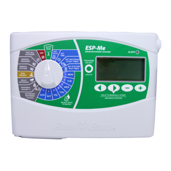
Rain Bird ESP-6LX+ Installation, Programming, And Operation Manual

Rain Bird ESP-6LX+ Installation, Programming, And Operation Manual

Esp-lx+ series; esp-lxi+ series
Table of Contents

Advertisement

Installation, Programming, & Operation Guide
ESP-LX+ & LXi+ Installation, Programming, & Operation Guide
ESP-LX+ and ESP-LXi+
Rain Bird Sales, Inc. - Turf Products
970 W. Sierra Madre, Azusa, CA 91702
www.rainbird.com
Indoor / Outdoor Models
ESP-6LX+
ESP-16LX+
ESP-8LX+
ESP-20LX+
ESP-12LX+ ESP-24LX+
Indoor Models
ESP-8LXi+
ESP-12LXi+
ESP-16LXi+
1
P/N 634415-B

Advertisement

Table of Contents
loading

Summary of Contents for Rain Bird ESP-6LX+

  • Page 1 Indoor / Outdoor Models ESP-6LX+ ESP-16LX+ ESP-8LX+ ESP-20LX+ ESP-12LX+ ESP-24LX+ Indoor Models ESP-8LXi+ ESP-12LXi+ ESP-16LXi+ Rain Bird Sales, Inc. - Turf Products ESP-LX+ & LXi+ Installation, Programming, & Operation Guide 970 W. Sierra Madre, Azusa, CA 91702 www.rainbird.com P/N 634415-B...
  • Page 2 * Additional discount not valid on clearance items, bundles or store specials. Discount applies to controller products only. Cannot be combined with other store discount codes. Valid at the Rain Bird Online Store only. Subject to change without notice. ® Registered trademark of Rain Bird Corporation.
  • Page 3: Table Of Contents

    TABLE O. CONTENTS Introduction ..................2 Run Program(s) Manually ............34 LX+ and LXi+ Series Controllers ..........2 Run Station(s) Manually .............. 35 Controller Stations ..............2 Run Test Program ............... 36 Station Layout ................3 Rapid Station Test Routine — RASTER™ ........... 37 Controls, Switches, and Indicators ..........
  • Page 4 WARNING: A CIRCUIT BREAKER OR CUTO.. SWITCH IS TO BE ATTENTION: UN DISJONCTEUR OU UN INTERRUPTEUR DOIT ETRE PROVIDED IN THE .IXED WIRING TO ISOLATE THE CONTROL- INSTALLE SUR LE PRIMAIRE POUR ISOLER LE PROGRAMMATEUR. LER. LA MEMOIRE EST MAINTENUE GRACE A UNE BATTERIE RE- MEMORY IS RETAINED BY A BATTERY, WHICH IS TO BE DIS- CHARGEABLE A DISPOSER SELON LA REGLEMENTATION POSED O.
  • Page 5: Introduction

    The ESP (Extra Simple Programming) -LX+, -LXi+ Series “remote ready” icon (shown at right) can be controller is an irrigation timing system for residential and light connected to Rain Bird’s Radio .requency (R.) commercial use. receivers (RM-1R & RMX-1R). The ESP-LX+ comes in 6-, 8-, 12-, 16-, 20-, or 24-station models, designed for either indoor or outdoor use.
  • Page 6: Station Layout

    Station Layout ESP-LX+ & LXi+ Installation, Programming, & Operation Guide...
  • Page 7: Controls, Switches, And Indicators

    Controls, Switches, and Indicators This illustration shows the controls, switches, and indicators on ESP-LX+ and LXi+ controllers, including: .ault LED — flashes when the controller senses a station short circuit. Clear .ault Button — used to turn off the .ault LED and clear the flashing LCD Error indicator after the fault has been corrected.
  • Page 8 Watering Suspended by Sensor LED — glows when watering is prevented by a moisture sensor. Sensor Bypass Switch — used to tell the controller to obey or ignore input from a moisture sensor system. (Sensor systems are optional.) Stations Slide Switch — used to select one of the station rows around the Programming Dial.
  • Page 9: Programming The Controller

    PROGRAMMING THE CONTROLLER Definitions Start time(s) - the time(s) of day that the program Programming is the process of telling the controller exactly • when and how long you want to water. The controller opens begins; this is the time that the first station in the program and closes the remote control valves according to the pro- begins watering;...
  • Page 10: Programming Checklist

    Programming Checklist To program the ESP-LX+ or LXi+ controller for the first time, we recommend that you complete the following steps in order. .or your convenience, a check-off box ( ) is provided for each step. .ill out Programming Chart ..........Page 8 Set master valve / pump starts for each station (optional).
  • Page 11: Ill Out Programming Chart

    .ill Out Programming Chart for 5 minutes. The entire program takes about an hour. Before you begin programming, fill out the Programming Chart Enter the watering run time (in hours and minutes) for each and attach it to the inside of the controller door. A sample station assigned to Program A.
  • Page 13: Clear All Program Information

    Clear All Program Information To ensure you begin with a “clean” setup, clear the controller of all existing program settings. Turn the dial to “O...” Hold down “ON” and “MAN. START/ADV.” for about seven seconds until the display reads INITSYS and then begins to scroll.
  • Page 14: Set Time

    Set Time Before you can program the controller, you must set its internal clock to the correct time and date. Turn the dial to “TIME & CALENDAR.” The hour digits in the display flash. Press ñ or ò to set the current hour. Make sure the AM/ PM indicator is set to the correct designation.
  • Page 15: Set Date

    Set Date Press “MAN. START/ADV.” until the date (1/JAN/95) shows in the display. The month flashes in the display. Press ñ or ò to set the current month. Press “MAN. START/ADV.” The day number flashes in the display. Press ñ or ò to set the current day of the month. Press “MAN.
  • Page 16: Select Program

    Select Program .our independent programs are available in the ESP-LX+, Programs A, B, and C are not allowed to overlap each other. If LXi+ Series controller: A, B, C, and D-drip. Multiple indepen- they are programmed to overlap, programs A, B, or C will dent programs let you enter watering schedules to meet the “stack”...
  • Page 17: Set Watering Day Cycle

    Set Watering Day Cycle Each program can operate in one of four watering day cycles: 3. ODD waters only on odd-numbered days of the month. See page 18. 1. CUSTOM waters on the days of the week you select. See the instructions below.
  • Page 18 Turn the dial to “MON.” The display shows the selected day and either “ON” or “O...” ON means the selected day is a watering day. O.. means watering doesn’t take place on that day. Press ñ or ò to set the day ON or O... Turn the dial to the next day of the week.
  • Page 19: Cyclical

    Cyclical To set a cyclical schedule: Turn the dial to “DAY CYCLE.” The display shows the currently selected program. If the program you want is not displayed, press “PGM” until it appears. Press ñ or ò until “CYCLIC” appears in the display. Press “MAN.
  • Page 20 Press “MAN. START/ADV.” The DAYS REMAINING digit flashes. Press ñ or ò to set the number of days remaining before the next watering day. “0” means that today is a watering day. So if you want watering to begin tomorrow, set the days remaining to “1.”...
  • Page 21: Odd/Even Cycle

    Odd/Even Cycle To set an odd/even cycle: Turn the dial to “DAY CYCLE.” The display shows the currently selected program. If the program you want is not displayed, press “PGM” until it appears. Press ñ or ò until “ODD” or “EVEN” appears in the display.
  • Page 22: Set Station Watering Times

    Set Station Watering Times You can set any station to run from 0 to 12 hours. .or the first two hours, you can set the watering time in one-minute incre- ments. .or the remaining 10 hours, you can set the watering time in 10-minute increments.
  • Page 23 If the program you want is not displayed, press “PGM” until it appears. Press ñ or ò to set the length of time you want the station to run. Repeat steps 2 - 5 for all stations. If you do not want to include a station in the program, set the run time to zero.
  • Page 24: Set Program Start Times

    Set Program Start Times You may assign up to six start times to each program per day. A program may start on any quarter hour. Multiple start times let you run a program more than once on each watering day. .or example if you are growing new lawn seed, you may want to water several times a day to keep the seedbed or top dressing damp.
  • Page 25 Press ñ or ò to set the start time. Start times are available in 15-minute intervals throughout the day. To eliminate a start time, leave the dial on “PROGRAM START TIMES.” Choose the start time to be deleted and push “MAN. START / ADVANCE”...
  • Page 26: Set Water Budget

    Set Water Budget In addition, you can use the 0% setting to shut off a program The water budget feature lets you increase or decrease the run temporarily. times of all stations on each program by a selected percentage. You can set the percentage from 0 to 300, in increments of one Water budget percentages are calculated based on the percentage point.
  • Page 27: Set Station Delays

    Set Station Delays You can set a different station delay for each program. A The station delay feature lets you program a pause between the end of one station’s watering operation and the beginning station delay applies to all stations on a given program. of the next station’s operation.
  • Page 28 “DELAY” appears in the display momentarily, followed by the delay time. If the program you want is not displayed, press “PGM” until it appears. Press ñ or ò to set the delay time. To cancel station delay, set the delay time to zero. NOTE: The display initially shows the delay time in seconds (“SEC”).
  • Page 29: Set Mv / Pump Starts

    Set MV / Pump Starts You can assign a master valve relay or a pump start relay to The MV / Pump start setting affects the station in all programs each station. This means that any time the station operates, the to which it is assigned.
  • Page 30 The “ON” or “O..” flashes in the display. Press ñ for ON or ò for O... To set another station, press “MAN. START/ADV.” Repeat steps 2 - 6 for each station you want to set. Turn the dial to “AUTO.” ESP-LX+ &...
  • Page 31: Set Rain Delay

    Set Rain Delay ESP-LX+ and -LXi+ controllers let you manually delay NOTE: The Rain Delay feature lets you set a delay watering for up to 14 days. .or example, if rainy weather lasts period manually. If you have an automatic rain sensor attached to your system, see the instructions on for 2 or 3 days, you can set a Rain Delay of 5 or 6 days to let the landscape dry out before resuming normal watering.
  • Page 32: Set Calendar Days O

    Set Calendar Days O.. Permanently set the 31st day of any month O... This setting The Calendar Day O.. feature lets you: • complies with local watering ordinances that prohibit watering on the 31st. Unlike settings for other days of the month, this Temporarily suspend watering on a specific day of the •...
  • Page 33 Press “MAN. START/ADV.” The ON or O.. setting flashes. Press ñ to set the day ON or ò to set the day O... Turn the dial to “AUTO.” When an O.. day occurs, the display shows “NON” (for non-watering day), and no watering occurs.
  • Page 34: Set Sensor System And Bypass Switch

    NOTE: .or this feature to operate properly, the sensor system that interrupts watering when a “wet” condition is must be connected according to the instructions on detected. .or example, if you have a Rain Bird Rain Check™ page 54. sensor connected to the controller, irrigation will be prevented when rainfall reaches the shutoff level in the sensor’s collector...
  • Page 35 To bypass the sensor, set the sensor bypass switch to “O...” The controller will ignore any sensor signals, and normal watering schedules will resume. This setting also lets you run programs and stations manually. ESP-LX+ & LXi+ Installation, Programming, & Operation Guide...
  • Page 36: Operating The Controller

    OPERATING THE CONTROLLER After you have programmed the controller, you will normally set In addition, you can run a test program to test the operation of it to operate automatically. all stations on the system. To operate automatically, run programs or stations manually, or run a test program, the You can also manually run one or more programs, and you can controller should be connected to a 120 volt AC power source manually operate a single station or several stations.
  • Page 37: Run Program(S) Manually

    Run Program(s) Manually NOTE: To run a program manually, please follow the instructions below carefully. Unlike other ESP controllers, ESP-LX+ and -LXi+ controllers have completely independent programs. Therefore, you must select a program before you press the “MAN. START / ADV.” button. Turn the dial to “AUTO.”...
  • Page 38: Run Station(S) Manually

    Run Station(s) Manually On 12-, 16-, 20-, and 24-station models, set the “STATIONS” slide switch to the block of stations containing the one you want to run. Turn the dial to the station number you want in the “WATERING TIME PER STATION” section of the dial. The display shows the currently selected program, the station number, and the station’s run time.
  • Page 39: Run Test Program

    Run Test Program The controller’s built-in test program will run each station that has a non-zero watering time assigned to it. When you run the test program, the controller will operate each station in numerical sequence, from lowest to highest. You can use this program to check the operation of all the sprinklers in the system.
  • Page 40: Rapid Station Test Routine — Raster™

    RAPID STATION TEST ROUTINE — RASTER™ Introduction The RASTER is available on indoor and outdoor versions of Rain Bird’s RApid Station TEst Routine (RASTER) lets you Rain Bird’s ESP-LX+ and -LXi+ controllers. diagnose and troubleshoot field wiring, solenoid, and controller problems quickly and easily.
  • Page 41: Raster Operation

    RASTER Operation Running a RASTER (Rapid Station Test Routine) NOTE: To run the RASTER, the controller must be connected to a 120 Volt AC power source (230 Volt for international models). Turn the Programming Dial to “O...” Press and release the “ON” and “O..” buttons at the same time.
  • Page 42  Press the “MAN START/ADV” button to begin the RASTER. The display shows “TEST IO,” and the .AULT Indicator light flashes once as the RASTER confirms the proper operation of the controller’s front panel lights. The RASTER then automatically checks the controller’s master valve and each station valve (in numerical order).
  • Page 43: Valve Testing

    Valve Testing The display briefly shows “TEST” (may flash too rapidly to be seen) and the station number (or “MV” for “master valve”) being tested. The display shows the valve’s operating condition (“PASS,” “.AIL,” “OPEN,” or “SHORT”), followed by the station number (up to 24 stations, depending on controller model).
  • Page 44 Call Rain Bird Technical Assistance at 800-247-3782, or contact your local authorized Rain Bird distributor to service your controller. ESP-LX+ & LXi+ Installation, Programming, & Operation Guide...
  • Page 45 Any valve displaying “OPEN” or “SHORT” should be checked for field wiring or other circuit problems. See “Troubleshooting Open and Shorted Valves Circuits” on page 43 for more information. To exit the RASTER, turn the Programming Dial from “O..” to “AUTO” (or any other dial position). The controller returns to normal operation, awaiting its next scheduled start time.
  • Page 46: Troubleshooting Open And Shorted Valve Circuits

    Troubleshooting Open and Shorted Valve Circuits Open Circuits An “OPEN” condition reported by the RASTER indicates a complete break in the current flow between the controller and the valve. NOTE: The RASTER will display an “OPEN” condition if no valve solenoid is connected to the controller station.
  • Page 47: Short Circuits

    Short Circuits A “SHORT” condition reported by the RASTER indicates an Loose or corroded wire connections on the controller’s • unintended re-routing of current flow somewhere between the terminal strip or at the valve solenoid controller and the valve. Malfunctioning components on the controller’s internal •...
  • Page 48: Installing The Controller

    INSTALLING THE CONTROLLER The ESP-LXi+ controller must be installed indoors only. The “i” This section of the manual explains how to mount the controller in the model number stands for “indoors.” on the wall and connect the wiring. NOTE: This controller must be installed in compliance The ESP-LX+ controller may be installed either indoors or with local electrical codes.
  • Page 49: Select Location

    Select Location Allow at least 6¾" (17,2 cm) of clearance above the .ollow these guidelines to select a location for the controller: cabinet door so the hinge pin can be removed to service the controller. Select an area protected from vandalism, where the user can easily reach the controller.
  • Page 51: Remove Door And .Ace Panel

    Remove Door and .ace Panel Before you mount the controller, we recommend that you Press down on the upper flexible hinge to release the remove the door and face panel. Although these steps are not hinge knob from its hole in the cabinet. absolutely necessary, they will make installation more conve- nient.
  • Page 53: Mount Controller On Wall

    Mount Controller on Wall .or narrow stud installations, drive an appropriate fastener The ESP-LX+ has four mounting holes on the back of the cabinet — three “keyhole” slots at the top of the cabinet and one for the type of wall into the middle keyhole mark. circular hole at the bottom of the cabinet.
  • Page 54 " & ESP-LX+ & LXi+ Installation, Programming, & Operation Guide...
  • Page 55: Connect .Ield Wires

    Connect .ield Wires .ield Wire Entrances The ESP-LX+ cabinet has four knockouts for routing field wires from the valves. Two are located on the underside of the cabinet, and two are located on the back of the cabinet. The underside of the cabinet has a hole sized for a 1" (2,6 cm) PVC male adapter so you can easily install a 1"...
  • Page 56: Station Valve Wiring

    Station Valve Wiring Connect each valve by its own separate power wire to one of the numbered terminals on the ESP-LX+ terminal strip, as shown in the illustration. You may connect up to two 24 VAC, 7VA solenoid valves per station. You may use the special Valve Test position to help identify valve stations BUT NOT for permanent connections.
  • Page 57: Sensor System Wiring

    Sensor System Wiring NOTE: Complete this section only if your system has an automatic rain sensor. If you are not connecting a sensor to the controller, make sure the supplied jumper is installed on the two SENSOR terminals on the controller’s vertical terminal strip.
  • Page 58: Pump Start Relay Wiring

    Pump Start Relay Wiring NOTE: Complete this section only if your system requires a pump start relay. The MV terminal on the controller’s terminal strip can be used to connect a pump start relay. Connect one lead of the 24VAC pump start relay to the MV terminal and the other lead to the common wire, as shown in the illustration.
  • Page 59: Connect Main Power Wires

    Connect Main Power Wires ESP-LX+ (Outdoor / Indoor Controller) WARNING: To prevent electrical shock, make sure all NOTE: To connect main power wires on the supply power is O.. before connecting these wires. ESP-LXi+ indoor-only controller, see the instructions Electrical shock can cause severe injury or death. on page 60.
  • Page 60 If you wish to bring the power supply wires through the wall on which you mount the controller, use the ½" (1,3 cm) knockout in the rear of the cabinet. Also remove the circular cutout in the flame-retardant fiberboard liner at the rear of the high-voltage compartment. .or safety purposes, be sure to seal the unused entry at the bottom of the cabinet.
  • Page 61 Bring three supply wires from the power source through the conduit into the high-voltage compartment. Strip the insulation from the incoming wires to expose about ½" (1,3 cm) of bare wire. Using a code-approved wire connector, connect the wires as follows: On 117-120 VAC models (U.S.), connect the black •...
  • Page 62 NOTE: The ground wires MUST be connected to provide electrical surge protection. Verify that all connections are secure. Then close the cover of the high-voltage compartment and secure it with the screw. V A C G N D C O M C O M CAUTION C A U T I O N...
  • Page 63: Esp-Lxi+ (Indoor Only Controller)

    ESP-LXi+ (Indoor-Only Controller) The ESP-LXi+ controller (117 VAC model only) has an external transformer that reduces standard supply voltage to 24 VAC to operate the valves connected to the controller. You will need to connect the three wires from the transformer to the vertical terminal strip in the controller cabinet.
  • Page 64 On the vertical terminal strip, connect the green forked wire to the terminal labeled “GND.” NOTE: The green ground wire MUST be connected Protective properly to provide electrical surge protection. cover Snap open the protective cover and connect one of the remaining two forked wires to one of the terminals labeled “24 VAC.”...
  • Page 65: Install Battery

    Install Battery NOTE: Memory of the time and date is retained by a The 9-Volt rechargeable nickel metal hydride (NiMH) battery battery which is to be disposed of in accordance supplied with the controller provides power to maintain the with local regulations. current time and date during a power outage.
  • Page 66 Slide the battery back into its compartment, and tighten the screw. The controller will fully charge the supplied NiMH battery in approximately 48 hours. The controller will continue to trickle-charge the battery whenever the controller is supplied with electrical power. ESP-LX+ &...
  • Page 67: Diagnostic Circuit Breaker

    After you find and repair the short circuit, press the “Clear Diagnostic Circuit Breaker .ault” button to clear the “.AULT” message from the display If the ESP-LX+ or ESP-LXi+ controller detects an electrical and stop the flashing .ault LED. Then you may wish to operate short circuit on one of the sprinkler system’s station wires or the station manually to make sure it works properly.
  • Page 68: Esp-Lx+ & Lxi+ Installation, Programming, & Operation Guide

    TROUBLESHOOTING SYMPTOM POSSIBLE CAUSE SOLUTION Program does not come Dial is set to O.. position. Set the dial to AUTO. on automatically. Start time has not been entered for the Turn the dial to PROGRAM START TIMES and check program. the start times entered for the program.
  • Page 69 SYMPTOM POSSIBLE CAUSE SOLUTION Display shows a station Sensor system is preventing irrigation. Turn the sensor bypass switch to O... If watering operating, but no watering (WATERING SUSPENDED BY SENSOR light is resumes, the sensor is operating properly, and no occurs.
  • Page 70 11. If the electrical surge did no permanent damage, the controller will accept programming commands and function normally. If the controller does not operate properly, contact Rain Bird Technical Assistance at 800-247-3782 (United States only). ESP-LX+ & LXi+ Installation, Programming, & Operation Guide...
  • Page 71 SYMPTOM POSSIBLE CAUSE SOLUTION Watering starts when it To cancel a program that has been manually started, 18. MAN START / ADV. key has been pressed. should not. set the dial to O.. for three seconds. Then set the dial back to AUTO. 19.
  • Page 72 NOTES ESP-LX+ & LXi+ Installation, Programming, & Operation Guide...
  • Page 73 • Consult the dealer or an experienced radio/TV technician for help. This equipment generates, uses, and can radiate radio frequency energy Changes or modifications not expressly approved by Rain Bird Sales, Inc., and, if not installed and used in accordance with the instructions, may could void the user’s authority to operate the equipment.

Table of Contents